1
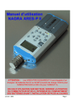
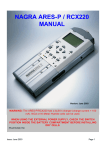
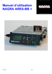
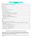
User’s Guide RCX C-Link Series: Remote Camera Link Extenders for use with Camera Link cameras Doc. 008-02368-03f Rev. 2012 August 09 Parhelia B.V. [email protected] www.parhelia-bv.com +31(0)10 741 00 28 Engineering Design Team (EDT), Inc. 1400 NW Compton Drive, Suite 315 Beaverton, OR 97006 p 503-690-1234 / 800-435-4320 f 503-690-1243 www.edt.com EDTTM and Engineering Design TeamTM are trademarks of Engineering Design Team, Inc. All other trademarks, service marks, and copyrights are the property of their respective owners†. © 1997-2012 Engineering Design Team, Inc. All rights reserved. EDT, Inc. 2 Terms of Use Agreement Definitions. This agreement, between Engineering Design Team, Inc. (“Seller”) and the user or distributor (“Buyer”), covers the use and distribution of the following items provided by Seller: a) the binary and all provided source code for any and all device drivers, software libraries, utilities, and example applications (collectively, “Software”); b) the binary and all provided source code for any and all configurable or programmable devices (collectively, “Firmware”); and c) the computer boards and all other physical components (collectively, “Hardware”). Software, Firmware, and Hardware are collectively referred to as “Products.” This agreement also covers Seller’s published Limited Warranty (“Warranty”) and all other published manuals and product information in physical, electronic, or any other form (“Documentation”). License. Seller grants Buyer the right to use or distribute Seller’s Software and Firmware Products solely to enable Seller’s Hardware Products. Seller’s Software and Firmware must be used on the same computer as Seller’s Hardware. Seller’s Products and Documentation are furnished under, and may be used only in accordance with, the terms of this agreement. By using or distributing Seller’s Products and Documentation, Buyer agrees to the terms of this agreement, as well as any additional agreements (such as a nondisclosure agreement) between Buyer and Seller. Export Restrictions. Buyer will not permit Seller’s Software, Firmware, or Hardware to be sent to, or used in, any other country except in compliance with applicable U.S. laws and regulations. For clarification or advice on such laws and regulations, Buyer should contact: U.S. Department of Commerce, Export Division, Washington, D.C., 20230, U.S.A. Limitation of Rights. Seller grants Buyer a royalty-free right to modify, reproduce, and distribute executable files using the Seller’s Software and Firmware, provided that: a) the source code and executable files will be used only with Seller’s Hardware; b) Buyer agrees to indemnify, hold harmless, and defend Seller from and against any claims or lawsuits, including attorneys’ fees, that arise or result from the use or distribution of Buyer’s products containing Seller’s Products. Seller’s Hardware may not be copied or recreated in any form or by any means without Seller’s express written consent. No Liability for Consequential Damages. In no event will Seller, its directors, officers, employees, or agents be liable to Buyer for any consequential, incidental, or indirect damages (including damages for business interruptions, loss of business profits or information, and the like) arising out of the use or inability to use the Products, even if Seller has been advised of the possibility of such damages. Because some jurisdictions do not allow the exclusion or limitation of liability for consequential or incidental damages, the above limitations may not apply to Buyer. Seller’s liability to Buyer for actual damages for any cause whatsoever, and regardless of the form of the action (whether in contract, product liability, tort including negligence, or otherwise) will be limited to fifty U.S. dollars ($50.00). Limited Hardware Warranty. Seller warrants that the Hardware it manufactures and sells shall be free of defects in materials and workmanship for a period of 12 months from date of shipment to initial Buyer. This warranty does not apply to any product that is misused, abused, repaired, or otherwise modified by Buyer or others. Seller’s sole obligation for breach of this warranty shall be to repair or replace (F.O.B. Seller’s plant, Beaverton, Oregon, USA) any goods that are found to be non-conforming or defective as specified by Buyer within 30 days of discovery of any defect. Buyer shall bear all installation and transportation expenses, and all other incidental expenses and damages. Limitation of Liability. In no event shall Seller be liable for any type of special consequential, incidental, or penal damages, whether such damages arise from, or are a result of, breach of contract, warranty, tort (including negligence), strict liability, or otherwise. All references to damages herein shall include, but not be limited to: loss of profit or revenue; loss of use of the goods or associated equipment; costs of substitute goods, equipment, or facilities; downtime costs; or claims for damages. Seller shall not be liable for any loss, claim, expense, or damage caused by, contributed to, or arising out of the acts or omissions of Buyer, whether negligent or otherwise. No Other Warranties. Seller makes no other warranties, express or implied, including without limitation the implied warranties of merchantability and fitness for a particular purpose, regarding Seller’s Products or Documentation. Seller does not warrant, guarantee, or make any representations regarding the use or the results of the use of the Products or Documentation or their correctness, accuracy, reliability, currentness, or otherwise. All risk related to the results and performance of the Products and Documentation is assumed by Buyer. The exclusion of implied warranties is not permitted by some jurisdictions. The above exclusion may not apply to Buyer. Disclaimer. Seller’s Products and Documentation, including this document, are subject to change without notice. Documentation does not represent a commitment from Seller. EDT, Inc. 3 Contents Contents....................................................................................................................................................... 4 Overview ...................................................................................................................................................... 5 Care and Cautions .......................................................................................................................... 5 Related Resources.......................................................................................................................... 6 Connecting the Extender Assembly ............................................................................................................. 7 Mounting the Extender .................................................................................................................... 8 Base Mode ...................................................................................................................................... 8 With a standard framegrabber ........................................................................................... 8 With a FOX framegrabber .................................................................................................. 9 Medium or Full Mode ...................................................................................................................... 9 With a standard framegrabber ......................................................................................... 10 With a FOX framegrabber ................................................................................................ 11 Eighty-bit packing............................................................................................................. 11 The LED ..................................................................................................................................................... 11 Configuration and LED Configuration Codes ............................................................................................. 11 Base Mode .................................................................................................................................... 12 Medium or Full Mode .................................................................................................................... 13 Resetting or Changing the Operating Mode.................................................................................. 13 Backward Compatibility................................................................................................................. 14 Status and LED Status Codes ................................................................................................................... 15 Firmware .................................................................................................................................................... 16 Versions ........................................................................................................................................ 16 Querying, Verifying, and Updating ................................................................................................ 16 Transceivers............................................................................................................................................... 18 Coaxial Cable............................................................................................................................................. 18 Pinouts ....................................................................................................................................................... 19 Camera Link.................................................................................................................................. 19 Power ............................................................................................................................................ 20 Cable assembly – Lemo to loose wire ............................................................................. 20 Cable assembly – Lemo to male DB9.............................................................................. 20 Cable assembly – Lemo to female DB9 RS232............................................................... 21 Cable assembly – Lemo resync ....................................................................................... 22 Power Supply ............................................................................................................................................. 22 Dimensions ................................................................................................................................................ 24 Alternative Mounting and Connecting Methods ......................................................................................... 25 Mounting Holes ............................................................................................................................. 25 Adapter Cabling ............................................................................................................................ 25 EDT, Inc. 4 RCX C-Link Series: Remote Camera Link Extenders Overview EDT’s RCX-series remote Camera Link extenders are compact modules that can be used to extend Camera Link data over fiberoptic or coaxial cabling. All components work just as they do with Camera Link cabling. This guide covers the following extenders: the RCX C-Link, which works with fiberoptic cable; and the RCX C-Link Coax2, which works with coaxial cable. Thus, for simplicity, this guide will refer to them as follows: • RCX C-Link Fiber extender • RCX C-Link Coax2 Coax extender Two extenders can link a camera to a standard framegrabber via fiber or coaxial cable; or one extender can connect a camera to an EDT FOX framegrabber, which has fiberoptic transceivers built in. Specially configured pairs are available for medium or full mode operation (fiber version only). NOTE All EDT extenders and framegrabbers mentioned in this guide are for Camera Link. For details on our legacy AIA product, RCX LVDS / RS422, see its product page at www.edt.com. Care and Cautions Your EDT extender is built to withstand a variety of extreme conditions, as listed in the specifications on its datasheet (see Related Resources on page 6). However, it is nonetheless a high-performance component which, for optimal results, should be treated with care, as detailed below. • The extender must be protected from even momentary power spikes over 18 volts. • The connectors – especially the fiberoptic transceivers – must be kept clean and dry. If you suspect the presence of moisture or debris in the connectors, you should blast a burst of compressed air: — directly into the ports to dislodge any debris that has collected there; and — away from the electronic components to blow out any moisture that has collected in the air nozzle. CAUTION To avoid damaging your eyesight, never look directly into any transceiver. EDT, Inc. 5 RCX C-Link Series Overview Related Resources The resources below may be helpful or necessary for your applications. • To find complete EDT information on any EDT product, go to www.edt.com and find the appropriate product page. That page will provide links to the product’s datasheet specifications and user’s guide. • To find EDT information that is not related to a specific EDT product (for example, installation packages or cable pinouts for multiple products), go to www.edt.com and look in Product Documentation. EDT Resource Detail Web link • Application programming interface HTML and PDF versions www.edt.com/manuals.html • Installation packages Software / firmware www.edt.com/software.html • Specifications for EDT products Datasheets www.edt.com (find by product name) • Documentation for EDT products User’s guides " (Product Documentation page) • Cabling and pinout documentation Details on cabling and pinouts " (Product Documentation page) Standard / Specification For From Web link • PCI / PCIe PCI / PCIe bus PCI Special Interest Group (PCI SIG) www.pcisig.com • Camera Link Camera Link Vision Online (VO) www.visiononline.org • IRIG-B IRIG-B timestamping Inter Range Instrumentation Group mod B EDT, Inc. 2012 August 09 irigb.com 6 RCX C-Link Series Connecting the Extender Assembly Connecting the Extender Assembly Each extender unit is factory-preset and labeled to connect to either a camera or a framegrabber (Figure 1). Each unit, in order to work properly, must be connected to the device for which it was preset and labeled. NOTE If you reconfigure your extender for a different device, relabel the extender to avoid future confusion. Figure 1. Fiberoptic extender, labeled with factory presets This label shows the unit’s factory presets, including: • the end for which the unit was preset (camera or framegrabber); • the operating mode for which the unit was preset (see Configuration and LED Configuration Codes on page 11). IMPORTANT: Full / medium mode units are not interchangeable with base mode units. One exception is X-channel camera-end units (part numbers 02188 and 02281), which can be reconfigured from full / medium mode to base mode (and vice versa) via a firmware update. For details, see Firmware on page 16. Once you have checked the labeling, you can connect each extender as explained below. • Device end: Attach the correct device (camera or framegrabber) to the extender’s MDR26 connector. • Cable end: Attach the correct cable to the extender’s cable connectors. Figure 2 shows the extender connectors and other features, including the LED (see The LED on page 11). Figure 2. Connectors and features on EDT extenders Device end of an extender An extender connected to a camera MDR26 Cable end of a fiberoptic extender Cable end of a coaxial extender thumbscrews LC duplex fiberoptic connector: SMA coaxial connectors: transmit receive transmit receive LED LED power supply connector EDT, Inc. power supply connector 2012 August 09 7 RCX C-Link Series Connecting the Extender Assembly Mounting the Extender To mount an extender, use the thumbscrews or one of the alternative methods detailed in Alternative Mounting and Connecting Methods on page 25. To mount a coax extender, you must use one of those alternative methods. Base Mode For this setup, you’ll need two extenders (one at the camera end and one at the framegrabber end) or, if you use an EDT FOX framegrabber, just one extender (at the camera end). In base mode, each pixel clock transfers 24 bits of video data from the camera’s X channel. The extender can transfer four camera control signals and has a bidirectional serial interface between framegrabber and camera. NOTE The extender generates its own pixel clock, so the clock rate into the framegrabber may exceed the rate of the camera. Thus, the amount of time spent in blanking will vary from line to line and frame to frame. With a standard framegrabber For a base-mode system with a standard framegrabber, you will need two extenders: one at the camera end and one at the framegrabber end (see Figure 3). Figure 3. Base mode: multiple extenders + standard framegrabber To set up this system: 1. Install the framegrabber according to its user’s guide (for EDT user’s guides, see Related Resources on page 6). 2. Verify the extenders are configured properly (see Configuration and LED Configuration Codes on page 11) – one for the camera end, and the other for the framegrabber end. 3. Turn off power to all devices. 4. Connect the extender labeled “Camera End” to the MDR26 connector on the camera (see Figure 2). 5. Connect the extender labeled “Framegrabber End” to the MDR26 connector on the framegrabber. 6. Connect the two extenders to each other with the appropriate fiberoptic or coaxial cable. 7. Connect the power supply to the power connector on the back of the extender. 8. Turn on power to all devices. 9. Verify each LED shows a steady light (see Status and LED Status Codes on page 15). EDT, Inc. 2012 August 09 8 RCX C-Link Series Connecting the Extender Assembly With a FOX framegrabber A FOX framegrabber has fiberoptics built in, so a base-mode system with a FOX framegrabber requires only one extender per camera (see Figure 4). Figure 4. Base mode: one extender + FOX framegrabber To set up this system: 1. Install the framegrabber according to its EDT user’s guide (see Related Resources on page 6). 2. Verify the extender is configured properly (see Configuration and LED Configuration Codes on page 11). 3. Turn off power to all devices. 4. Connect the extender to the MDR26 connector on the camera (see Figure 2). 5. Connect the extender to the desired transceiver on the framegrabber (channel 0 is the transceiver physically closest to the PCI bus) with fiberoptic cable. 6. Connect the power supply to the power connector on the back of the extender. 7. Turn on power to all devices. 8. Verify each LED shows a steady light (see Status and LED Status Codes on page 15). Medium or Full Mode A medium- or full-mode system requires multiple extenders, as explained below. On a medium- or full-mode Camera Link camera, there are two MDR26 connectors. • The primary connector operates the same way as the base-mode interface: each pixel clock transfers 24 bits of video data from the camera’s X channel. The primary connector also can transfer four camera control signals, and it has a bidirectional serial interface between framegrabber and camera. • The secondary connector transfers video data for the Y and Z channels: — Medium-mode cameras transfer 24 bits of video data for the Y channel. — Full-mode cameras transfer an additional 24 bits for the Z channel. Thus, the standard full-mode configuration transfers 72 bits of video data — 24 bits each for the X, Y, and Z camera channels. The X-channel extenders (one at the camera end and one at the framegrabber end) operate as a basemode extension cord, with one fiber for video data from camera to framegrabber, and the other for control signals from framegrabber to camera. The YZ-channel extender at the camera end has two fiberoptic transmitters, with both fibers carrying video data to the framegrabber. Many framegrabbers require that the video data presented at the primary and secondary connectors must be synchronized to within a fraction of a pixel clock. The section entitled Cable assembly – Lemo resync on EDT, Inc. 2012 August 09 9 RCX C-Link Series Connecting the Extender Assembly page 22 describes a common pixel clock for both extenders at the framegrabber end, and other synchronizing signals to ensure that the starting pixel of each raster lines up across the X, Y and Z channels. The resync cable also supplies power to the extenders. CAUTION To avoid damaging your components, you should verify that the entire system is connected properly before you apply power to any component. In particular, do not apply power to the resync cable while you are connecting it to, or disconnecting it from, an extender. With a standard framegrabber For medium- or full-mode operation with a standard framegrabber, you will need four extenders: two at the camera end, and two at the framegrabber end (see Figure 5). NOTE Each extender unit is physically different from the others, so you cannot simply change the configuration codes and use the units interchangeably. Figure 5. Full mode: multiple extenders + standard framegrabber To set up this system: 1. Install your Camera Link framegrabber and software as instructed by its manufacturer. 2. Verify extenders are configured properly (see Configuration and LED Configuration Codes on page 11). 3. Turn off power to all devices. 4. Connect the extender labeled X Channel Camera to the camera's primary MDR26 connector. 5. Connect the extender labeled YZ Channel Camera to the camera’s secondary MDR26 connector. 6. Connect the extender labeled X Channel FG to the framegrabber’s primary MDR26 connector. 7. Connect the extender labeled YZ Channel FG to the framegrabber’s secondary MDR26 connector. 8. Connect the two power supplies with coaxial power connectors to the two camera-end extenders. 9. Verify that you have the correct resync cable for your camera (see Figure 5) and connect the cable to both extenders at the framegrabber end. The two ends of the resync cable are interchangeable. 10. Connect the power supply with the 9-pin D-shell connector to the resync cable connector. EDT, Inc. 2012 August 09 10 RCX C-Link Series The LED 11. Connect an LC duplex fiber from the X-channel extender at the camera end to the X-channel extender at the framegrabber end. 12. Connect an LC duplex fiber from the YZ-channel extender at the camera end to the YZ-channel extender at the framegrabber end. 13. Turn on power to all devices. 14. Verify each LED shows a steady light (see Status and LED Status Codes on page 15). With a FOX framegrabber A FOX framegrabber for medium and full mode is currently in development. Eighty-bit packing Certain full-mode cameras, such as the Basler A04k and Mikrotron MC1310 and MC1311, will reassign the Spare, Data-valid, and Frame-valid control signals to allow a transfer of up to 80 bits of data per pixel clock. Your extender can be configured with a configuration code to accommodate these cameras. Configuration codes of 1-5 (at the camera end) and 2-5 (at the framegrabber end) allow 80-bit packing at frequencies of 60–72 MHz. The 72 MHz upper limit is determined by the bandwidth available over the fiber, but is sufficient to support all modes currently available on the cameras specified above. The LED Each extender has a light-emitting diode (LED), as in Figure 2. By displaying various patterns of blinks (blink codes), the LED communicates information about the extender’s configuration and status, as follows. At power-on, the LED blinks a configuration code (indicating the operating mode for which the extender is configured) one time, and then blinks rapidly as the firmware loads. After power-on, the LED continuously displays a status code (indicating whether the unit is working properly or has errors). The LED also is used when resetting or changing the operating mode. The two types of LED codes are explained more fully in Configuration and LED Configuration Codes on page 11 and Status and LED Status Codes on page 15. Configuration and LED Configuration Codes Your EDT extender can support a wide range of camera models and data transfer rates, depending on the extender model and operating mode selected. For fiber extenders, standard firmware will support most base-mode cameras from 20 to 80 MHz, with UART data rates of up to 19.2 Kb/s, and full-mode operation at 60–80 MHz. For coax extenders, standard firmware will support most base-mode cameras from 20 to 60 MHz, with UART data rates of up to 19.2 Kb/s. Each extender is factory-preset for the operating mode that was specified in the product order. The operating mode is selected and indicated through LED configuration codes, as explained below. Each extender is configured for the desired operating mode through a pattern of blinks called the LED configuration code. This code, displayed once at power-on, consists of two digits, each represented by a certain number of blinks. The two digits are separated by a pause, shown in this guide as a hyphen. For example, a configuration code of “one blink, pause, one blink” is shown in this guide as 1-1. EDT, Inc. 2012 August 09 11 RCX C-Link Series Configuration and LED Configuration Codes A first digit of 1 indicates that the unit is configured for the camera end; a first digit of 2 indicates that the unit is configured for the framegrabber end. The second digit must be the same for both ends (camera and framegrabber). With a FOX framegrabber, there is no extender at the framegrabber end, so the configuration code is set at the camera end only. For a typical base-mode system, a configuration code of 1-1 at the camera end and 2-1 at the framegrabber end permits standard base-mode operation at clock frequencies of 20–40 MHz. For a typical full mode system, a configuration code of 1-4 on both extenders at the camera end, and a configuration code of 2-4 on both at the framegrabber end, allows standard full-mode operation at clock frequencies of 60–80 MHz. On the configuration code label for a medium- or full-mode system, X Channel refers to the primary MDR26 connnector on the camera or framegrabber, and YZ Channel refers to the secondary connector. Base Mode Table 1 shows the operating modes of an extender in base mode (EDT firmware revsion 11 or higher). Table 1. LED configuration codes – base mode Code End Camera Clock Rate Constraints Link Rate Extender Type 1-1 camera 20–40 MHz 24 bits 1.25 Gb/s Fiber & coax 1-2 camera 20–60 MHz 16 bits 1.25 Gb/s Fiber & coax 1-3 camera 20–60 MHz 24 bits 2.5 Gb/s* Fiber only 1-4 camera 60–80 MHz 24 bits 2.5 Gb/s* Fiber only 2-1 framegrabber 40 MHz 24 bits 1.25 Gb/s Fiber & coax 2-2 framegrabber 60 MHz 16 bits 1.25 Gb/s Fiber & coax 2-3 framegrabber 60 MHz 24 bits 2.5 Gb/s* Fiber & coax 2-4 framegrabber 80 MHz 24 bits 2.5 Gb/s* Fiber only 3-3 firmware update (see Firmware on page 16) 1.25 Gb/s Fiber & coax 2 fast, 2 slow, 2 fast Error: unsupported configuration code entered * PCI DV FOX supports rates only up to 1.25 Gb, so it works only with RCX C-Links configured at 1-1 or 1-2. Cameras operating between 40 and 60 MHz are usually best served by configuration codes 1-3 and 2-3. If the camera needs only 16 data bits or fewer transferred per clock cycle (instead of all 24), it is possible to use configuration codes 1-2 and 2-2 instead, and thus operate the link at 1.25 Gb/s for longer range and lower power dissipation. The selection of 16-bit mode is made only at the framegrabber end through configuration code 2-2, or through the directive mode16: 1 in a FOX configuration file; this information is communicated over the fiber to the extender at the camera end. (At the camera end, configuration codes 1-1 and 1-2 are identical.) At reset (and whenever the extender cannot lock to the camera clock), the extender initializes to assume that the Camera Link Data-Valid signal is never asserted, and ignores it. Many Pulnix cameras do not assert Data-Valid, so this behavior is useful for those using such cameras. The first occurrence of Data-Valid true from the camera causes the extender to use Data-Valid to qualify video data from that point on. In the case of a dual-tap camera, the Camera Link pixel clock is half the camera’s pixel rate. For example, a dual-tap 12-bit camera with a 40 MHz Camera Link clock sends 80 million pixels per second. This camera is compatible with the extender in configuration code 1-1. EDT, Inc. 2012 August 09 12 RCX C-Link Series Configuration and LED Configuration Codes Medium or Full Mode Table 2 shows the operating modes of an extender in medium or full mode (EDT firmware rev. 11 or higher). NOTE This table is for the fiberoptic extender only, as the coaxial extender is available for base mode only. Table 2. LED configuration codes – medium or full mode Code End Camera Clock Rate Constraints Link Rate 1-1 camera 20–40 MHz 72 bits 1.25 Gb/s 1-2 [undefined] – – – 1-3 camera 20–60 MHz 72 bits 2.5 Gb/s 1-4 camera 60–80 MHz 72 bits 2.5 Gb/s 1-5 camera 60–72 MHz for 80-bit full-mode cameras 2.5 Gb/s 2-1 framegrabber 20–40 MHz* 72 bits 1.25 Gb/s 2-2 [undefined] – – – 2-3 framegrabber 20–60 MHz* 72 bits 2.5 Gb/s 2-4 framegrabber 60–80 MHz* 72 bits 2.5 Gb/s 2-5 framegrabber 60–72 MHz* for 80-bit full-mode cameras 2.5 Gb/s 3-3 firmware update (see Firmware on page 16) 2 fast, 2 slow, 2 fast Error: unsupported configuration code entered 1.25 Gb/s * For camera clock rate, the resync cable determines the actual frequency. For full-mode cameras, which typically operate at 60 to 80 MHz, configuration codes of 1-4 (camera end) and 2-4 (framegrabber end) should work. For full-mode cameras that transfer 80 bits per clock cycle, use configuration codes of 1-5 (camera end) and 2-5 (framegrabber end). For medium-mode cameras, which typically operate at 40 MHz, configuration codes of 1-1 (camera end) and 2-1 (framegrabber end) should work. For instructions on verifying and updating the firmware, see Firmware on page 16. Resetting or Changing the Operating Mode Your extender is factory-preset for the operating mode that was specified in the product order. However, if you need to reset or change the operating mode, you can do so by setting the LED configuration code. NOTE If you change the operating mode, be sure to relabel the extender to prevent future confusion. To reset or change the operating mode (configuration code): 1. Turn off the power to the extender, and disconnect the extender from everything except a power supply. NOTE EDT recommends connecting the power supply to a power strip or some other device that allows easy access to both the power and the extender at the same time. This is because, as you follow the steps below, it may become necessary to turn off the power and restart the process (see step 4). 2. Press the recessed button on the bottom of the extender with a fine, blunt point – such as the tip of a ballpoint pen – as in Figure 6. EDT, Inc. 2012 August 09 13 RCX C-Link Series Configuration and LED Configuration Codes Figure 6. Pressing the recessed button 3. Still pressing the button, turn on the power; the LED will turn on. 4. Release the button within two seconds (if you press the button longer than two seconds, the LED will start blinking diagnostically and you will need to restart the process from step 1). 5. Release the button; the LED will turn off. NOTE Before proceeding, be sure you know which configuration code you want (see Configuration and LED Configuration Codes on page 11), because you’ll need to enter it quickly when the LED starts blinking. 6. Press the button, let the LED start blinking, and release the button after the correct number of blinks for the first digit; then repeat for the second digit. For example, for a configuration code of 2-1, press the button for two blinks, and release; then press the button for one blink, and release. As soon as you enter the second digit, the extender saves your selection into flash memory and the LED starts blinking in that pattern. If the pattern is not what you wanted, start over from Step 1. NOTE If an unsupported code is entered, the LED will display two fast, two slow, and two fast blinks, indicating that an error has occurred and the code has not been saved to memory. 7. Cycle power to the extender without pressing the button. When the extender is powered on without the button pressed, the LED blinks the configuration code once and blinks rapidly as the firmware loads; then it continuously displays the extender’s status (see Status and LED Status Codes on page 15). Backward Compatibility For details on backward compatibility, see Firmware on page 16. EDT, Inc. 2012 August 09 14 RCX C-Link Series Status and LED Status Codes Status and LED Status Codes As previously discussed, at power-on the LED blinks the extender’s configuration code one time, and then blinks rapidly as the firmware loads. After power-on, the LED continuously displays the extender’s status code, which indicates whether the unit is working properly or has errors (see Table 3). Table 3. LED status codes If LED shows... It means... Steady light All OK – everything is working properly. Slow blinks There is an error from the other end. The typical causes are: (1Hz) • The extender at the other end has no power, or its operating mode does not match the operating mode on this extender (see Configuration and LED Configuration Codes on page 11). • The cable connection is compromised, either by incorrect or damaged cabling, or by moisture or debris in the extender’s cable connectors (see Care and Cautions on page 5). Fast blinks (10Hz) Both slow and fast blinks 2 fast + 2 slow + 2 fast blinks No light EDT, Inc. There is an error from the camera to the extender, related to the camera’s pixel clock. If the fast blink is on the camera-end extender: either the camera has no power, or the operating mode on the extender does not match the operating mode on the camera (see Configuration and LED Configuration Codes on page 11). If the fast blink is on the framegrabber-end extender: either the extender or the resync cable is faulty. There is at least one slow-blink error and at least one fast-blink error. The extender is configured with an unsupported operating mode (see Configuration and LED Configuration Codes on page 11). The extender has no power or is faulty. 2012 August 09 15 RCX C-Link Series Firmware Firmware If you are using EDT FOX or PCI Express framegrabbers and fiber extenders in base or medium mode, you can query and, if appropriate, update the firmware. If you are using anything else, contact EDT to update the firmware. To avoid version problems, EDT recommends against doing a firmware update unless you are convinced it is necessary. If it is necessary, you can use the utility rcxload to query the firmware, verify it against a provided firmware file, and update the firmware. Versions EDT extenders are factory-preset with the files shown in Table 4. Table 4. FPGA configuration files for RCX-series extenders Camera Link operating mode Channel FPGA configuration file Base [no channels] rgb11.rcx Medium X mx11.rcx Y my11.rcx X fx11.rcx YZ fyz11.rcx Full IMPORTANT: Full / medium mode units are not interchangeable with base mode units. One exception is Xchannel camera-end units (part numbers 02188 and 02281), which can be reconfigured from full / medium mode to base mode (and vice versa) via a firmware update. If your extender unit is using standard firmware older than revision 11, the unit will support camera speeds of only 20–40 MHz at 1.25 Gb/s, using a configuration code of 1-1 (ignore Data-Valid), 1-2 (use Data-Valid), or 2-1 (framegrabber end). For backward compatibility, firmware revisions of 11 or later will behave identically for configuration codes 1-1 and 1-2. As of firmware revision 11, Data-Valid is automatically detected. If you use configuration code 2-2 at the framegrabber end for 16-bit mode, you can use the corresponding configuration code of 1-2 at the camera end. NOTE To determine whether your firmware is revision 11 or later, you can enter configuration code 3-5 (see Configuration and LED Configuration Codes on page 11). If the LED then blinks two fast, two slow, two fast (indicating an unsupported configuration code), then you have firmware of revision 11 or later. Querying, Verifying, and Updating For base or medium mode, follow the steps below to query, verify, and update the firmware. CAUTION To avoid corrupting the firmware on the extender, do not interrupt the update by pressing Ctrl-C or turning off the power while the update is in progress. 1. Set up your system as instructed in this guide (see Connecting the Extender Assembly on page 7). 2. Run pciload with no arguments to ensure that the system recognizes the EDT framegrabber. Typical output appears as shown below. EDT, Inc. 2012 August 09 16 RCX C-Link Series Firmware pdv unit 0 (pci dv fox): XC2S200 PCI FPGA, AMD 29LV081B 8MB FPROM s/n AP0064, p/n 019-02103-11, i/f fpga xc2s400e, rev 11 clock 40 Mhz, opt f2 Sector 0 Sector 1 Sector 2 PROM id: <dvtlk4_3v.ncd 2s200fg456 2005/06/10 14:58:10> Sector 3 PROM id: <dvtlk4_5v.ncd 2s200fg456 2005/06/10 14:58:16> 3. Configure the extender with code 3-3 (see Configuration and LED Configuration Codes on page 11). 4. Power-cycle the extender. 5. If you are using a FOX framegrabber, ensure the fiberoptic cable is connected to channel 0 (the channel physically closest to the PCI bus). The extender need not be connected to a camera. 6. Query the extender, to ensure it is there and recognized, by entering rcxload with no arguments. After you start rcxload, the LEDs on both devices will be lighted and not blinking. Typical output appears thus: pdv unit sector 0 sector 1 sector 2 sector 3 sector 4 sector 5 0 (pci dv fox) chan. 0 RCX module: [10000]: <rgb11cm60_a01.ncd 2vp2fg256 2006/03/30 20:05:34> [38000]: <rgb11cm80_a01.ncd 2vp2fg256 2006/03/30 20:12:36> [60000]: <rgb11fg40_a01.ncd 2vp2fg256 2006/03/30 19:57:41> [88000]: <rgb11fg60_a01.ncd 2vp2fg256 2006/03/30 20:02:08> [b0000]: <rgb11fg80_a01.ncd 2vp2fg256 2006/03/30 20:09:30> [d8000]: <fud02b.ncd 2vp2fg256 2006/03/28 15:59:19> If your output appears faulty, check the configuration code, cables, and connections. If you still have problems, email the output to [email protected]. 7. Assuming correct output from step 6 above, you can perform either or both of the following operations. — To verify (compare) the firmware in your EDT installation package against the firmware already loaded on your extender via flash memory, run... rcxload -u 0 -v flash/rcx/file.rcx ...replacing file.rcx with the filename of the current firmware revision. The utility compares the firmware in the extender with the firmware in the specified firmware file. If they are the same, the utility reports verified and 0 errors; if not, it reports not verified and lists the errors. — To update the firmware, if you determine that an update is necessary, run... rcxload -u 0 flash/rcx/file.rcx ...replacing file.rcx with the filename of the current firmware revision. The filename must be a valid .rcx file. EDT software packages ship with the current .rcx files in the flash/rcx subdirectory. The README file in the package has information about any .rcx file updates, including the specific filename of the current revision. After a successful update, configure the extender for the desired operating mode (see Configuration and LED Configuration Codes on page 11). NOTE If rcxload reports an error within a section flagged as “critical,” do not power-cycle the extender; instead, repeat the procedure. If you still get errors, leave the extender powered on and contact EDT. You can turn off the power to the computer and camera, and leave the extender powered on indefinitely. EDT, Inc. 2012 August 09 17 RCX C-Link Series Transceivers Transceivers The fiberoptic extender supports various types of transceivers and fiber, as shown in Table 5. Table 5. Transceiver + Fiber Combinations Range Standard Extended Fiber Type Multi-mode fiber (MMF) Single-mode fiber (SMF) Thickness (microns) Wavelength 62.5 Maximum length (meters) at 1.25 Gb/s at 2.5 Gb/s 850 nm 300 150 50.0 850 nm 500 250 9.0 1310 nm 10,000 5000 Alternatively, the following transceivers are available as options. • Single fiber transceivers (distances up to 60 km): These have an integrated passive optical multiplexer and transmit data in each direction over one fiber using different colors of light – especially useful when going through an optical rotary joint. • CWDM transceivers (extended range of 5 km or more, 1310 nm, single-fiber PON) – These use up to 16 different colors of light, with the light split and combined by passive optical multiplexers that are external to the extender. They support up to twelve different cameras simultaneously over a single fiber. • DualTX and DualRX transceivers – In full mode, these are used on the secondary Camera Link connector because it must carry twice as much data as the primary connector. Coaxial Cable The coaxial extender has two SMA connectors – one for data in, and one for data out. The cable used must have a corresponding SMA connector at each end. The maximum range is determined by the dB of loss at 625 MHz. EDT recommends using a cable that keeps the amount of loss under 20 dB at 625 MHz. The cabling must have an impedance of 50 ohms. One cable type that meets all of these requirements is 50-ohm RG58, which has an SMA connector at each end and a typical loss of 11 to 15 dB per 100 feet. EDT, Inc. 2012 August 09 18 RCX C-Link Series Pinouts Pinouts This section provides pinout information for the Camera Link and power connectors. Camera Link Table 6 shows the MDR26 connector pinout for Camera Link signals (base, medium, and full mode). Table 6. Pinout – MDR26 Connector EDT, Inc. Camera end Framegrabber end 1 14 2 15 3 16 4 17 5 18 6 19 7 20 8 21 9 22 10 23 11 24 12 25 13 26 1 14 25 12 24 11 23 10 22 9 21 8 20 7 19 6 18 5 17 4 16 3 15 2 13 26 Camera Link signal base mode (primary connector) inner shield inner shield X0– X0+ X1– X1+ X2– X2+ Xclk– Xclk+ X3– X3+ SerTC+ SerTC– SerTFG– SerTFG+ CC1– CC1+ CC2+ CC2– CC3– CC3+ CC4+ CC4– inner shield inner shield 2012 August 09 Camera Link signal medium mode (secondary connector) inner shield inner shield Y0– Y0+ Y1– Y1+ Y2– Y2+ Yclk– Yclk+ Y3– Y3+ unused unused unused unused unused unused unused unused unused unused unused unused inner shield inner shield Camera Link signal full mode (secondary connector) inner shield inner shield Y0– Y0+ Y1– Y1+ Y2– Y2+ Yclk– Yclk+ Y3– Y3+ 100 ohms terminated Z0– Z0+ Z1– Z1+ Z2– Z2+ Zclk– Zclk+ Z3– Z3+ inner shield inner shield 19 RCX C-Link Series Pinouts Power The power connector on the extender is either a standard coaxial Switchcraft or an optional Lemo. Pin information for both is shown in Figure 7. Figure 7. Pinout – Standard Switchcraft Connector and Optional Lemo Connector (Switchcraft) 1 Outer ring is ground. Pin 1 is power to extender (+4.75 to +18 V DC). (Lemo) 1 2 6 5 7 3 4 Key in connector barrel (at top). Pin 2 is power to extender (+4.75 to +18 V DC). Pin 7 is ground (for signals and power). Pins 1, 3, 4, 5, and 6 (defined by firmware used in extender) typically are used at CMOS +3.3 V signal levels, though pins 1,6 and 3,4 can be configured as LVDS pairs. With the Lemo, you can use various cables that allow auxiliary signals. (On medium- and full-mode systems using the resync cable option, the extenders at the framegrabber end must use Lemo connectors.) Cable assembly – Lemo to loose wire The Lemo to loose wire (EDT part #016-02650) can be wired as needed or connected to various types of connectors, depending on what you need for your application. Table 7. Pinout – Lemo to loose wire Lemo Pin Wire Color Standard Firmware (rgb11.rcx) Signal Level 1 (output) green AUX_TX, primary auxiliary transmit UART CMOS +3.3 V 2 red power to extender +4.75 to +18 V 3 (output) orange AUX2_TX, secondary auxiliary transmit CMOS +3.3 V 4 (input) brown AUX2_RX, secondary auxiliary receive CMOS +3.3 V 5 white SYNC, can be configured as an outgoing copy of the camera’s frame-valid signal CMOS +3.3 V 6 (input) blue AUX_RX, primary auxiliary receive UART CMOS +3.3 V 7 black ground ground Comments All five CMOS 3.3 V signals go to FPGA I/O 3.3V pins using series 100-ohm resistors. Custom firmware can be used to configure these pins as input or output. Cable assembly – Lemo to male DB9 The male DB9 (EDT part #016-02718) supports signals that can be used as an auxiliary signaling system for a variety of purposes. For example, custom firmware could allow the auxiliary signals to be used to control the camera’s pan and servo motors. It is also possible to set up a hardware trigger that is local to either end. If you wish to explore these options, contact EDT. Unlike the DB9 in the female assembly, this DB9 has no looped-back signals or integrated level conversion. EDT, Inc. 2012 August 09 20 RCX C-Link Series Pinouts Table 8 shows the pinout and how the standard firmware uses each wire. Table 8. Pinout – Male DB9 Cable Lemo Pin Color DB9 Pin Standard Firmware (rgb11.rcx) Signal Level – – 1 [unused] – – – 6 [unused] – 1 (output) green 2 AUX_TX, primary auxiliary transmit UART CMOS +3.3 V 2 red 9 power to extender +4.75 to +18 V 3 (output) orange 7 AUX2_TX, secondary auxiliary transmit CMOS +3.3 V 4 (input) brown 8 AUX2_RX, secondary auxiliary receive CMOS +3.3 V 5 white 4 SYNC, can be configured as an outgoing copy of the camera’s frame-valid signal CMOS +3.3 V 6 (input) blue 3 AUX_RX, primary auxiliary receive UART CMOS +3.3 V 7 black 5 ground ground Comments All five CMOS 3.3 V signals go to FPGA I/O 3.3V pins using series 100-ohm resistors. Custom firmware can be used to configure these pins as input or output. Cable assembly – Lemo to female DB9 RS232 The female DB9 (EDT part #016-02445) supports integrated CMOS +3.3 V to RS232 level converters on a small circuit board inside the DB9 connector shell. This cable is designed to plug in directly to a host computer serial port. The cable offers an auxiliary UART connection over the fiber, in addition to the UART normally associated with the Camera Link standard. This auxiliary UART can be used, for example, to control the camera’s pan and zoom servo motors from the host at 19.2 Kb/s or less. Alternatively, it can be used for other low bandwidth signals. Unlike the DB9 in the male assembly, this DB9 does not supply power to the extender. Instead, a red wire (power) and a black wire (ground), both 24 inches long, are left loose so you can hook up your own power source. The required power is 4.75 to 18 V DC. Table 9 shows the pinout and how the standard firmware (in rgb11.rcx) uses each wire. DB9 pins 1, 4, and 6 are wired together and unconnected, 7 and 8 also are wired together, and 9 also is unconnected; these signals are not otherwise used. Table 9. Pinout – Female DB9 Cable EDT, Inc. Lemo Pin Wire Color DB9 Pin Standard Firmware (rgb11.rcx) Signal Level – – 1 [unused] – – – 6 [unused] – 1 (output) green 2 AUX_TX, primary auxiliary transmit UART RS232 (at DB9) to CMOS +3.3 V (at Lemo) 2 red 9 power to extender +4.75 to +18 V (red wire out) 3 orange 7 reserved – 4 brown 8 reserved – 5 white 4 reserved – 6 (input) blue 3 AUX_RX, primary auxiliary receive UART RS232 (at DB9) to CMOS +3.3 V (at Lemo) 7 black 5 ground ground (black wire out) 2012 August 09 21 RCX C-Link Series Power Supply Cable assembly – Lemo resync The resync cable, for medium or full mode, sends a common clock signal from an oscillator inside the DB9 shell to each of the two extenders at the framegrabber end. This cable also allows the X channel extender to signal the YZ channel extender when to start each raster. The two Lemo connectors on the resync cable are interchangeable. The resync cable must have an oscillator frequency greater than or equal to the camera pixel clock rate. The pixel clock re-created for the framegrabber is asynchronous to that generated by the camera; thus, the amount of time spent in horizontal blanking varies from one raster line to the next. If the camera's clock rate is slower than that of the resync cable, a greater percentage of time will be spent in horizontal blanking at the framegrabber. Resync cables for 40, 60, and 80 MHz are available (see Related Resources on page 6). From the tables under Configuration and LED Configuration Codes on page 11, select a configuration code with a frequency range that is included in the frequency generated by the cable assembly. Table 10 shows the pinout for this cable with a male DB9 connector. Table 10. Pinout – Resync Cable with Male DB9 Lemo Pin Lemo Signal DB9 Signal DB9 Pin 1 START_RASTER+, LVDS signal from X to YZ extender [unconnected] — 2 power power 9 3 CLOCK+, LVDS pixel clock into X and YZ extenders [unconnected] — 4 CLOCK-, LVDS pixel clock into X and YZ extenders [unconnected] — 5 reserved [unconnected] — 6 START_RASTER-, LVDS signal from X to YZ extender [unconnected] — 7 ground ground 5 If you use the resync cable, you will need a power source as well (see Power Supply, below). Power Supply Each extender has an internal switching regulator that supports voltages of 4.75 to 18 volts DC. For pin information and polarity on the standard Switchcraft and the optional Lemo connector, see Power on page 20. CAUTION To avoid damage to the extender, EDT recommends that you protect it from power spikes over 18 V, use voltages at the lower end of the range, and never reverse the polarity of the power connector. EDT, Inc. 2012 August 09 22 RCX C-Link Series Power Supply Table 11 shows the base-mode power supply requirements for an extender at the camera end. Table 11. Base-mode power supply for extender at camera end U.S. International International with DB9 connector Voltage in 100–240 V, 50–60 Hz from AC mains 100–240 V, 50–60 Hz from AC mains 100–240 V, 50–60 Hz from AC mains Voltage out 5 V, 1 A (DC); power supply includes a U.S.-standard power plug. 5 V, 2 A (DC); power supply includes four international power plug adapters. 5 V, 2 A (DC); power supply includes four international power plug adapters. Connector Switchcraft 760K Switchcraft 760K DB9 female In full mode with a standard framegrabber, the power required for each end (camera and framegrabber) is always under 6 watts – and typically closer to 4 watts – per end. This power is spread across two extender (typically 1.5 watts for the X channel unit, and 2.5 watts for the YZ channel unit). The two extenders at the camera end can use either of the two power supplies with the Switchcraft connectors, while the two extenders at the framegrabber end can receive power from the EDT resync cable through a female DB9 connector. The resync cable connects to the extenders through two interchangeable Lemo connectors. EDT, Inc. 2012 August 09 23 RCX C-Link Series Appendix A Dimensions This section covers the dimensions for EDT extenders. Figure 8 shows the dimensions of a typical extender. The power connector dimension of 0.31 inch is for the standard power connector; the optional Lemo connector on the fiber version is approximately 0.35 inch. NOTE Connector dimensions are approximate; for precise dimensions, see the manufacturer’s specifications. Figure 8. Extender Dimensions Figure 9 shows a typical value for cable clearance; the exact value is dependent upon the cable used. Figure 9. Cable Clearance EDT, Inc. 2012 August 09 24 Appendix Alternative Mounting and Connecting Methods Your setup may require an alternative method to mount an extender to a device. For example, to mount a coax extender (which has no thumbscrews), you’ll need to use one of these methods. Mounting Holes You can mount the extender via its mounting holes, as in Figure 10, and a custom (user-provided) bracket. Figure 10. Mounting Holes mounting holes CAUTION To avoid damage to the extender, mounting screws must not extend more than 0.2" into the case. See Dimensions on page 24. Adapter Cabling If you cannot mount your extender directly to your device, you can use an EDT adapter cable or an optional third-party cable. Figure 11 shows EDT’s half-meter cables, with part numbers and instructions. Figure 11. EDT extenders with EDT half-meter adapter cables Fiber extender + EDT adapter cable #016-02563 Coax extender + EDT adapter cable #016-03946 With this cable, screw the fiber extender’s thumbscrews through the end of the EDT cable and firmly into the MDR26 connector on the cable. With this cable, screw the screws (with washers) on the EDT cable through the cable backshell, and firmly into the MDR26 connector on the coax extender. Also, for devices with SDR (mini Camera Link) connectors, EDT offers a 3M MDR26 female to SDR26 male cable in two lengths: 1 meter (EDT part #016-013779); or 2 meters (EDT part #016-13740). RCX C-Link Series Alternative Mounting and Connecting Methods Revision Log Below is a history of modifications to this guide for EDT’s RCX C-Link Series. Date Rev 20120809 03f By Pp Detail PH 7 In section called Connecting the Extender Assembly... • In Figure 1, added this note: “IMPORTANT: Full / medium mode units are not interchangeable with base mode units. One exception is X-channel camera-end units (part numbers 02188 and 02281), which can be reconfigured from full / medium mode to base mode (and vice versa) via a firmware update. For details, see Firmware on page 16.” 20120809 03f PH 16 In section called Firmware... • Under Versions, in Table 4, added this note: “IMPORTANT: Full / medium mode units are not interchangeable with base mode units. One exception is X-channel camera-end units (part numbers 02188 and 02281), which can be reconfigured from full / medium mode to base mode (and vice versa) via a firmware update.” • Moved this note (formerly halfway down the page, under Querying, Verifying, and Updating - now slightly revised as follows) to go right under main Firmware heading: “If you are using EDT FOX or PCI Express framegrabbers and fiber extenders in base or medium mode, you can query and, if appropriate, update the firmware. If you are using anything else, contact EDT to update the firmware.” 20120515 03f PH All • Repaginated to use continuous arabic numerals from title page to end. • Implemented new terminology: Changed “digital video” to “vision” or “digital imaging.” 20120501 03e CH,JG, 12 PH • Under Firmware, Version, Table 4, in the row for Medium operating mode, in the column for Channel, changed the YZ to a Y only, per JG. 20120316 03e JG,PH • In Tables 7-9, specified which Lemo pins are input and which are output. 20111013 03d PH+RH, 8 CH, et al • Added note under Table: “PCI DV FOX supports rates only up to 1.25 Gb/s, so it works only with RCX C-Links configured at 1-1 or 1-2.” 20110629 03d RH,CH, 14 TL,PH • Revised Coaxial Cable main section to include more 50-ohm information and no 75-ohm information (not part-numbered). 20110624 03c RH,PH 14 • Added Coaxial Cable main section (with 50- and 75-ohm information). 20110624 03c RH,PH 14 • Deleted Options main head and moved its two subsections as follows: - made Transceivers a main section (moved above Pinouts); - renamed Power Connector (re. Lemo cable options) to Power and moved it under Pinouts. 20110624 03c RH,PH 16 • Made Camera Link pinout its own subsection (Camera Link) under Pinouts. 20110624 03c RH,PH 16,18 • In sections entitled Pinouts and Power Supply, added clarifying details and a figure showing the standard Switchcraft vs. the optional Lemo power connector. 20110523 03b CH,PH 18 • Under Power Supply, expanded the opening verbiage to: “Each extender has an internal switching regulator that supports voltages of 4.75 to 18 volts DC. The polarity for the power connector is center pin positive (+), outer collar negative (-). CAUTION - To avoid damage to the extender, EDT recommends that you protect it from power spikes over 18 V, use voltages at the lower end of the range, and never reverse the polarity of the power connector.” EDT, Inc. 16-17 2012 August 09 26 RCX C-Link Series Date Alternative Mounting and Connecting Methods Rev By Pp Detail 20110307 03b PH 16-17 • Under Options - Power Connector: - Loose wire – added new section and table for this option. - Male and female – reformatted tables to match loose wire assembly table. 20110216 03a PH 20 • Added to Appendix: information about SDR cable connectors. 20110211 03 PH All • Added information about new products (coax extender and PCIe framegrabber). 20100000 02 PH All • Updated guide with new page layout and formats. 20000000 01 LW All • Created new guide. EDT, Inc. 2012 August 09 27