1
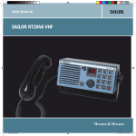
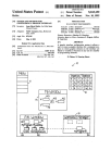
USER GUIDE Frescaire FR5000 Frescaire España S.L. Pol. Ind. Finca Lacy Calle el Tope Parc. D4. Apdo. Correos 224 3600 Elda Alicante CIF: B54502273 www.frescaire.com 1 USER GUIDE CONTENTS 1. INTRODUCTION ..................................................................................... 3 2. SECURITY WARNINGS ............................................................................ 5 3. GENERAL LAYOUT FR 5000 .................................................................... 6 3. DIMENSIONS FR-‐5000 AHU ................................................................... 7 4. FR5000 MAIN EXTERIOR PARTS ............................................................ 9 5. USE OF FR5000; END-‐USER THERMOSTAT GUIDE ............................... 11 5.1 Basic operation mode ................................................................ 12 5.2 Overview of the Three Main Operation-‐Modes: ........................ 13 5.3 The Five Sub Operating Modes: ................................................. 13 5.4 Standard User Parameters to Modify ......................................... 14 5.5 Parameter Number and Description .......................................... 15 6. MAINTENANCE AND SECURITY ........................................................... 16 7. SEASONAL AND POST SEASONAL MAINTENANCE ............................... 20 8. FREQUENTLY ASKED QUESTIONS ........................................................ 22 2 1. INTRODUCTION Congratulations! You have purchased the finest, most efficient air conditioner and environmental friendly air-‐handling unit. With your new Frescaire air conditioner, the benefits you get are better than any other product on the market: • 100% fresh, filtered, cool, and comfortable air with no added humidity • Uses up to 75% less electricity than traditional air conditioners • Cooling capacity increases as temperature increases…the hotter it gets, the better it works33 • Patented proven dew point-‐cooling technology • No CFC refrigerants to harm the environment • 2-‐year limited warranty • Low, easy maintenance The Frescaire line-‐up of just 2 models and modular conceptual design means that it can be installed in many places previously thought impossible. Frescaire AHU´s have been installed on roofs, on the ground, in attics, basements and through window and wall openings. The basic requirements are the same for all installations. By following the simple maintenance instructions in this manual your Frescaire AHU will provide years of comfortable, efficient, green cooling. 3 Should you have questions or maintenance performed, please contact your installer or distributor: Your installer is: 4 2. SECURITY WARNINGS Please read this user guide before putting the unit in operation. Please save these instructions for future reference. This is an electric appliance. Do not open any part of the unit without ensuring that there is no current flowing over the unit. Do not let children near the unit.. To be certain that there is no current flowing through the unit, turn off the lock-‐out, and lock it with a padlock. Important safety precautions: Read maintenance chapter or frequently asked questions for future precautions. In case of failure or malfunction, please call your distributor immediately. No internal elements of the unit need opening or manipulation, please do not open any internal part of the unit under the risk of injuries. 5 3. GENERAL LAYOUT FR 5000 6 3. DIMENSIONS FR-‐5000 AHU FR 5000 dimensions 7 The FR 5000 is an air-‐handling unit, designed to work using indirect evaporative cooling technology. This FR5000 can be used in mode ventilation or cooling mode. Technical features Model Model&5000 Nominal&supplied&airflow Maximum&supplied&airflow Inlet&air&conditions& Supply&air&conditions&nominal&airflow &mᶾ/h& &mᶾ/h& °C&/&%RH °C&/&%RH 31,5&/&42,7 22,8&/&71,3 ZielKAbbeg& nS¹ V/n◦/Hz kW A V A/M/B&&dB(A) GR40CKZID.DC.1R Variable 3˜380K480&50/60 2,1 3,66 400 67,5 &&&&&&&&&&&&&&&&&&mm &&&&&&&&&&&&&&&mm &&&&&&&&&&&&&&&&&&&&&mm 745 2.286 2.182 mm mm mm &&&&&&&&&&&&&&&&&&&&&&&&&&&&&&&&&kg Type Litres&/&Hour& &&&°C 500x500 385 500x100 390 R718 40 15°C&K&60°C 4000 5000 Fan& Fan&type Fan&frequency Voltage/phase/frequency Electrical&consumption&at&nominal&airflow Maximum¤t Voltage Sound&production&3&metres&at&nominal&airflow Unit& Unit&dimensions Width Length Height Inlet&airKoutlet&(hxw) Supply&airKoutlet&ØD ProcessKairKoutlet&(hxw) Net.&Weight Refrigerant& Water&consumption&Max. Operating&range Filter Filter*type Filter*Class Specified&models&and&specifications&are&subject&to&change Vokes&Air F7 8 4. FR5000 MAIN EXTERIOR PARTS The FR5000 unit consists of two main external elements: -‐Lock-‐out: It is a security connector, that manipulates the electrical current necessary for the correct function of the FR5000. It is fixed on the outer shell, and the button must be turned OFF before any type of manipulation is executed. -‐Electrical box: All the electrical components that are necessary for the correct function of the machine are located inside this box. There are two main electrical components that can be switched on and off. These components are respectively the: • Motor protection switch: 9 The Motor protection switch is a security switch that cuts the electrical current when overload occurs. It must be switched to it´s ON position for the correct function of the unit. Please do not, under any circumstance change the configuration of the electrical current under risk of fan failure and/or overload. If the switch is OFF , the fan will not run • Protective device fuse: The protective device fuse is the main connector fuse. It must be switched to it´s ON position for the correct function of the unit. This is the main fuse of the unit. 10 5. USE OF FR5000; END-‐USER THERMOSTAT GUIDE -‐Thermostat: Thermostat is the element that you will use to operate the FR5000 AHU. The thermostat is installed in the area/room where the supplied cooled air is diffused. Please ensure that the thermostat is not installed near a thermal heat emitting element, this could disrupt the internal thermometer values. Main Buttons: There are the thermostat buttons: • Occupancy button (ON/OFF) • Increase button • Decrease button Thermostat Screen 11 5.1 Basic operation mode Thermostat is designed to work with three principal operation-‐modes, which we will refer to as “Operative mode”, “Off mode” and “Forced ventilation”. Each basic operation mode has certain sub-‐modes at its disposal. The illustration below explains how we change from one basic mode to another. Every sub mode uses parameters to define the desired airflow conditions. When changing determined conditions, the respective parameter needs to be changed. Please refer to page nr. 15 for the full parameter list. We change between these modes as see on the next scheme: 12 5.2 Overview of the Three Main Operation-‐Modes: -‐Operative mode: The unit is operative over determined conditions that are defined by the selected sub-‐mode. This mode is the present mode when the unit is turned on. This mode can be chosen selecting the parameter nr. 45 of the configuration (1=unoccupied, 2=Stand-‐by, 3=Occupied). -‐Off mode: The unit is inactive with some exceptions defined by the selected mode. This mode can be chosen using the 46 parameter of the configuration (0=Off, 1=Unoccupied). -‐Forced ventilation: The unit is completely active. It is working on maximum capacity to achieve the temperature selected in the set point conditions. 5.3 The Five Sub Operating Modes: Off.-‐The unit is off, and will automatically activate when the temperature is lower than 8ºC (This temperature can be changed using parameter nr. 6 of the parameter menu. Please refer to page nr. 15 for the full parameter list). The OFF word without the temperature is displayed on the display when this mode is selected. Unoccupied.-‐The unit is off, but will automatically activate when the temperature is lower than 15ºC or high tan 30ºC. (This temperature can be changed by the parameters number 4 and 5 of the configuration). The OFF word with the temperature is displayed on the display when this mode is selected. Occupied.-‐The unit is on. This is the factory setup standard. In that case the unit works trying to obtain the cooling setup temperature (24ºC) and the heating setup temperature (22ºC). (Those temperatures can be changed by the parameters nr. 1 and 2) Temperature, occupancy indicator and the words heat or cool are showed on the display when this mode is selected. Stand-‐by.-‐The unit is on. However it is on stand-‐by on the range of a temperature 3ºC high the setup cooling temperature and 3ºC down the setup heating temperature. (This temperature can be changed by the parameter 3 of the configuration) Standby is displayed on the display when this mode is selected. Bypass.-‐The unit is on. The control is the same than in occupied mode, but the fan is forced to work on the maximum capacity. The thermostat has a connection to install an occupancy detector. If this mode is activated by this detector, this mode will be turned off 10 minutes after the people leave the room. (This value can be changed by the parameter 13 of the configuration). If the mode is activated by the occupancy 13 button, this mode will be turned off after 120 minutes (This value can be changed by the parameter 12 of the configuration) Forced ventilation indicator is displayed on display when this mode is selected. 5.4 Standard User Parameters to Modify Standard temperatures can be modified with the buttons “increase” and “decrease”. Pressing on INCREASE increases the current set point in steps of 0.5°C up to the max. limit (+3°C). Pressing on DECREASE decreases the current set point in steps of 0.5°C down to the min. limit (-‐3°C). Changing a Parameter It is possible to set different parameter values in a parameter menu. The parameter menu is accessed by simultaneously holding the INCREASE and DECREASE buttons depressed for about 5 seconds and then pressing the INCREASE button twice. The Service indicator will be displayed. First the display will show the parameter nr. 1. Scroll between parameters by using the INCREASE and DECREASE buttons. Press the Occupancy button to select the desired parameter. The parameter number will be replaced by the parameter value. The value can be changed using the INCREASE and DECREASE buttons. If a button is held depressed the value will start scrolling, first slowly and then with increasing speed in 3-‐4 steps with 2-‐3 seconds between steps. Acknowledge/Regret change To acknowledge and store a set parameter value, press the Occupancy button again, the display then returns to showing the parameter number. To retrieve the original value, i.e. the value before change, press the INCREASE and DECREASE buttons at the same time. The original value is shown on the display. 14 Return to normal display After a certain time, about 1 minute, or when the INCREASE and DECREASE buttons are pressed at the same time while in the menu, the display returns to the normal view. Exit is shown on the display after the last parameter. The parameter menu is exited by pressing the Occupancy button while in Exit. Pressing on INCREASE goes to the first parameter and pressing on DECREASE goes to the last parameter. Switching between heating and cooling set points is done automatically in the controller depending on the heating and cooling requirement. Choice of set point display, see parameter 74. 5.5 Parameter Number and Description The following parameters can be changed in the parameter menu: Parameter Description number 1 Basic set point heating 2 Basic set point cooling 3 Neutral zone at Stand-‐by. Heat sp. = Basic sp. Heat -‐3. Cool sp. = Basic sp. Cool +3. 4 Heat set point at Unoccupied 5 Cooling set point at Unoccupied 6 Frost protection set point 12 Time in bypass mode 45 Present operating mode: 1=Unoccupied, 2=Stand-‐by, 3=Occupied. Forced ventilation is not set in Occupied mode 46 State operating mode by depressing Occupancy button for 5 sec: 0=Off, 1=Unoccupied. Forced ventilation is not set in Occupied mode FS 22°C 24°C 3°C 15°C 30°C 8°C 120 min 3 1 15 6. MAINTENANCE AND SECURITY Failure to follow these instructions will shorten the life of your heat exchanger and result in a poor performance of your Frescaire air conditioner. The key to good maintenance is regular and systematic inspection of all parts. Inspection frequency is determined by the severity of the application and local conditions. Strict adherence to an inspection schedule is essential. This schedule should be offered by your distributor/installer. The location of your Frescaire air conditioner, will determine how often you should inspect your air handling unit. Air handling units operating in areas with excessive dust, cotton, pollen, leaves, or insects should perform inspection steps more frequently. You, as end user, could execute the minor maintenance operations. These are: Filter: We advise our users to change the filter every 4-‐6 months. When changing the filter: turn off and lock the lock-‐out, preferably with a keypad lock. Then open the filter cover, as stated in the picture below, extract it and and place the new filter and close the filter cover. 16 Fan: Regular fan maintenance should include the following: Check the fan blades for any wear or corrosion, as either could cause catastrophic failures. Check for the accumulation of material on the impeller surfaces, which could cause imbalance, resulting in vibration, excess noise, and premature bearing wear. During any maintenance, all bolts should be checked for tightness. Hydraulic System: Water delivery devices and piping (tubing) should be inspected to insure proper water flow. This includes all pipes leading to the air conditioner as well as the internal tubes that deliver water to the heat exchangers. 17 Check the water supply system for leaks, and repair if needed. Any leaks should be repaired immediately to assure proper water delivery to the unit. With the top lid removed, check the internal tubes of the water distribution system for leaks. Proper and consistent water flow to the heat exchanger cores is essential for efficient and proper unit operation. Heat Exchanger: The heart of the Frescaire air-‐handling unit is the heat exchanger. Each heat exchanger should be visually inspected when the air filters are replaced. If any debris is found it should be removed. If the heat exchangers appear to be damaged in any way contact your local distributor. 18 Casing The outer casing of the FR5000 unit is made of composite materials. We advise you to clean the casing with water and soap. Please ensure that no water enters the electronics or air-‐outlets. Do not manipulate or open any part of the unit while it is in operation. Before any operation, turn off and lock the lock-‐out, preferably with a keypad lock. We recommend an annual revision and complete maintenance operations are performed by authorized personnel from your local installer or distributor. The following chart gives and overview of the maintenance operation and regularity. The complete maintenance operations must be performed by authorized personnel from your local installer or distributor. Component Regularity Drainage: plugging revision and chemical cleaning Biannual Sprinkler: corrosion and dirty revision Annual Core: ecological product cleaning Annual 19 7. SEASONAL AND POST SEASONAL MAINTENANCE Failure to follow the following seasonal (winterization) shut down procedures may result inreduced performance of your Frescaire air conditioner • Inspect the unit to make sure that all safety devices and other parts are secure. • Turn the manual water supply valve off located outside the machine. • Remove the water supply line upstream the manual water supply valve. 20 • Remove the final connection from the water supply to the top side of the heat exchanger. • Turn on the unit for 5 minutes, the water must be drained by gravity, avoiding the freezing of the water, that could cause a rupture in the hydraulic system • Set the thermostat to “heating” or to the “Off” position. 21 8. FREQUENTLY ASKED QUESTIONS Thermostat does not turn on. • Check that the machine is connected to the electric inlet. Lockout, fan protection and motor protection switch must be in the ON position. Without electricity over the machine, thermostat could not works Fan does not move. • Motor protection switch The Motor protection switch is a security switch that cuts the electrical current when overload occurs. It must be switched to it´s ON position for the correct function of the unit. Please do not, under any circumstance change the configuration of the electrical current under risk of fan failure and/or overload. If the switch is OFF, the fan will not run. • Protective device fuse: The protective device fuse is the main connector fuse. It must be switched to it´s ON position for the correct function of the unit. This is the main fuse of the unit. Low airflow. • Check your settings in the thermostat. • Low air flows occur when there is a small difference between set temperature and outside air temperature • Check that the air inlet valve is not obstructed with any object. • Check the filter, poor maintenance reduces the air flow The airflow is not cool. • Check your settings in the thermostat. • Check your water connection, see if any leakage is visible on the outer casing, if so, and connect water connection correctly. • Low air flows occur when there is a small difference between set temperature and outside air temperature • Check that the air inlet valve is not obstructed with any object. • Check the filter, poor maintenance reduces the efficiency If any problems persist, please turn of the unit and call your local distributor or installing company. 22