1
Installation and user’s guide
H-2000-5254-02-B
TRS1 non-contact broken tool
detection system
© 2005 Renishaw plc. All rights reserved.
This document may not be copied or reproduced in whole or in part, or
transferred to any other media or language, by any means, without the
prior written permission of Renishaw.
The publication of material within this document does not imply
freedom from the patent rights of Renishaw plc.
Disclaimer
Considerable effort has been made to ensure that the contents of
this document are free from inaccuracies and omissions. However,
Renishaw makes no warranties with respect to the contents of this
document and specifically disclaims any implied warranties. Renishaw
reserves the right to make changes to this document and to the
product described herein without obligation to notify any person of such
changes.
Trademarks
RENISHAW® and the probe emblem used in the RENISHAW logo are
registered trademarks of Renishaw plc in the UK and other countries.
apply innovation is a trademark of Renishaw plc.
Adobe and Acrobat are either registered trademarks or trademarks
of Adobe Systems Incorporated in the United States and/or other
countries.
All other brand names and product names used in this document are
trade names, service marks, trademarks, or registered trademarks of
their respective owners.
Warranty
Equipment requiring attention under warranty must be returned to
your supplier. No claims will be considered where equipment has
been incorrectly installed or misused, or where repairs or adjustments
have been attempted by unauthorised persons. Prior consent must be
obtained in instances where Renishaw equipment is to be substituted
or omitted. Failure to comply with this requirement will invalidate the
warranty.
Patents
Features of the TRS1 non-contact broken tool detection system and
related products are subject to pending patent protection.
Renishaw part no: H-2000-5254-02-B
Issued: 03 2005
1
Contents
Preliminary information .................................................................................................................. 2
Warnings and cautions ................................................................................................................... 3
Laser warning labels and dimensions ............................................................................................ 4
General........................................................................................................................................... 5
Introduction ............................................................................................................................... 5
Software routines ...................................................................................................................... 5
Probe status display function .................................................................................................... 5
Bar graph displays..................................................................................................................... 5
TRS1 typical performance ......................................................................................................... 5
Installation ...................................................................................................................................... 6
Mounting ................................................................................................................................... 6
Air supply .................................................................................................................................. 7
Electrical connections: TRS1 to machine controller ....................................................................... 9
System set-up ................................................................................................................................ 10
Range setting ............................................................................................................................ 10
Determine the checking position ............................................................................................... 10
Cleanliness ................................................................................................................................ 11
Troubleshooting .............................................................................................................................. 12
Specification ................................................................................................................................... 13
Maintenance - TRS1 system .......................................................................................................... 14
Maintenance - air regulator unit...................................................................................................... 16
Parts list.......................................................................................................................................... 18
2
Preliminary information
FCC
Information to user (FCC Section 15.19)
EC DECLARATION OF CONFORMITY
Renishaw plc declares that the product:
Name
TRS1
Description
Non-contact broken tool detection system
has been manufactured in conformity with the following
standards:
BS EN 61326: 1998/
A1:1998/A2:2001
Electrical equipment for
measurement, control and
laboratory use - EMC
requirements. Immunity to annex
A - industrial locations. Emissions
to class A (non-domestic) limits.
BS EN 60825-1:1993/ Safety of laser products.
A2:2001
Part 1: Equipment
classification, requirements
and user’s guide.
and that it complies with the requirements of the following
directives (as amended):
89/336/EEC
73/23/EEC
Electromagnetic compatibility
Low voltage
The above information is summarised from the full
EC Declaration of Conformity. A copy is available from
Renishaw on request.
This device complies with Part 15 of the FCC rules.
Operation is subject to the following conditions:
1.
This device may not cause harmful interference.
2.
This device must accept any interference received,
including interference that may cause undesired
operation.
Information to user (FCC Section 15.105)
This equipment has been tested and found to comply with
the limits for a Class A digital device, pursuant to part 15
of the FCC Rules. These limits are designed to provide
reasonable protection against harmful interference when
the equipment is operated in a commercial environment.
This equipment generates, uses and can radiate
radio frequency energy and, if not installed and used
in accordance with this installation guide, may cause
harmful interference to radio communications. Operation
of this equipment in a residential area is likely to cause
harmful interference, in which case you will be required to
correct the interference at your own expense.
Information to user (FCC Section 15.21)
The user is cautioned that any changes or modifications
not expressly approved by Renishaw plc or authorised
representative could void the user’s authority to operate
the equipment.
Warnings and cautions
!
Warnings
3
Caution – Laser safety
Use of controls or adjustments or performance
of procedures other than those specified within
this publication may result in hazardous radiation
exposure.
The laser used in the Renishaw TRS1 non-contact
broken tool detection system emits continuous
visible red light at a wavelength of 670 nm and has
a power output of less than 1 mW.
Switch off the power supply before carrying out
maintenance on the TRS1 system.
The laser used is classified as a Class 2 product as
defined by British standard BS EN 60825-1:1993 +
A2: 2001.
When using the TRS1 basic safety precautions
must always be followed to reduce the risk of fire,
electric shock and personal injury, including the
following:
The laser complies with 21CFR 1040.10 except for
deviations pursuant to Laser Notice No. 50 dated
July 26, 2001.
● Read all instructions before operating this
product.
The standard BS EN 60825-1 directs to attach a
laser warning label and explanatory label.
● The device must only be installed and used by
competent, trained personnel.
A warning label and explanatory label are
permanently fixed to one side of the housing (see
page 4 for details). An adhesive warning label is
provided for attachment outside the machine.
● Use eye protection.
● Avoid inhalation of coolant vapour from the
machine tool.
● Do not block the air exiting the micro hole with
any part of the body.
● Do not look directly into the laser beam.
Ensure that the beam is not reflected into the
eyes via any reflective surface.
4
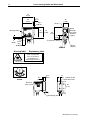
Laser warning labels and dimensions
73
(2.87)
68
(2.68)
Warning labels
3
(0.12)
Ø4.7
(0.19)
67
(2.64)
38
(1.50)
Rx lens
72
(2.83)
}
Signal
Strength
Bar graph
(Refer to
page 5)
83
(3.27)
32
(1.26)
5
(0.20)
4.5
(0.18)
Tx aperture Laser
19.8
(0.78) flat
Status
display
14
(0.55)
Warning label
Explanatory label
LASER RADIATION
DO NOT STARE INTO BEAM
CLASS 2 LASER PRODUCT
1mW MAXIMUM OUTPUT
EMITTED WAVELENGTH 670nm
COMPLIES WITH 21 CFR 1040.10 AND IEC 60825-1/A2:2001
Receiver focus
screw
6.5
(0.26)
21.5
(0.85)
Receiver
focus screw
19
(0.75) 2 identical slots
3 for M4 screws
(0.12)
36
(1.42)
2
(0.08)
18.5
(0.73)
M6 Through bolt
Dimensions in mm (in)
General
5
Introduction
This section of the guide describes how to install, and maintain the Renishaw TRS1 non-contact broken
tool detection system.
The TRS1 is a laser-based non-contact broken tool detection system specifically designed for solid
centred tools, for example drills and taps.
The tool is rotated at 1000 rpm and is moved into the laser beam. The output is activated and the output
changes when the tool is detected by the receiver.
Software routines
Examples of programs for high-speed broken tool detection of solid tools are available for a wide range of
machine controller types. Please refer to the CD in the back of this book.
Probe status display function
The probe status display on the front of the system indicates the status to the user.
Display
colour
Status
Not lit
Power off
Red
Broken tool or no tool
Green
Good tool detected
Bar graph displays
The bar graph displays indicate the level of light falling on the receiver. If the bar graph display is not lit
this means no light has been detected by the receiver.
Green
Green
Amber
Amber
Align TRS1 to
illuminate highest
number
Red
TRS1 typical performance
The TRS1 system is capable of detecting a Ø1 mm bright drill at 2 m (6.56 ft) and a Ø0.5 mm bright drill
at 0.3 m (0.984 ft), dependent on installation, set-up and tool type/condition.
Note: For a tool to be detected, sufficient light must be reflected back to the TRS1 system. Before
running the broken tool cycle, ensure that every tool can be detected by the TRS1 system, as this varies
with range, installation and set-up.
6
Installation - mounting
Mounting
The mounting surface must be rigid sufficiently so the laser beam does not move due to vibration or
flexing of the mounting surface. If the laser beam moves, then tools, particularly those of small diameter,
may not be detected.
Notes: Where practical, the TRS1 system must be mounted so that the laser beam does not shine out of
the machine. Where this is not possible, open paths must be located above or below eye level.
A beam stop in the form of a piece of black tape fixed to the outside of the machine window may be used.
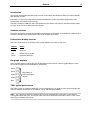
Mount the TRS1 as close to the tools to be detected as possible, so that the beam is at 90 degrees
to the end of the tool. The TRS1 system must be installed perpendicular to the tool axis for optimum
performance, refer to the diagram on page 10. Performance will be affected if perpendicularity is not
achieved, and this effect increases with separation.
● The tool must be able to move in the Z axis relative to the TRS1 system, so that tools of different
lengths can be checked.
● The closer the TRS1 is to the tool, the greater the reflected light level, so small diameter tools or
those with a blue finish are more easily detected.
● To maximise service life, mount the system such that swarf contamination will be at a minimum.
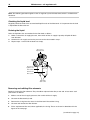
Note: The TRS1 system can be mounted on its side or upright.
1.
Mount the system on a rigid part of the machine, refer to the diagram below for possible mounting
configurations. Tighten the M6 mounting screw using a 10 mm AF spanner and a 5 mm AF hex
driver to 8.3 Nm (6.12 lbf. ft). Tighten the M4 mounting screws using a 3 mm AF hex driver to 2.6 Nm
(1.92 lbf. ft).
2.
Fit the cable conduit and air spring protector to the system, refer to the diagram below.
3.
Connect the cable to the machine controller, refer to the diagram on page 9.
M6 screw
(supplied)
Dismantling
adjuster
bracket
M4 screws
(not supplied)
M4 screws
(not supplied)
Cable conduit
M6 nut (supplied)
Part of machine structure
Rear mounting
Air spring protector
Side mounting
Installation - air supply
7
Air supply
The TRS1 uses a clean air supply to protect the laser transmitter from the machine environment. It is
recommended that the air supply be switched on at all times to prevent contamination.
The air supply to the TRS1 system must conform to ISO 8573-1 air quality of class 1.7.2 and be moisturefree. If the air quality cannot be guaranteed, an optional air filtration system is available from Renishaw
– see the parts lists on page 18.
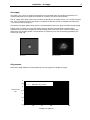
Also refer to the graph below which gives the recommended air pressure against installed air pipe length.
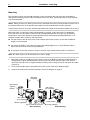
Failure of the air supply may cause the TRS1 system to become contaminated. Contamination is
indicated if the laser spot is dispersed instead of being sharp when shone on to a piece of white paper.
Refer to the two diagrams below. If contamination is suspected, carry out the cleaning procedure (see
Cleaning on page 14).
Good spot
Dispersed spot
Air pressure
Refer to the graph below for recommended air pressure against the length of air pipe.
5
Recommended air pressure
4.5
Minimum air pressure
4
Air pressure
bar
3.5
3
2.5
2
1.5
5
10
15
20
Length of air pipe (m)
25
30
8
Installation - air supply
!
CAUTION: Do not connect the TRS1 system to an oiled air supply. Purge all piping prior to
connection.
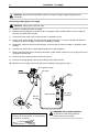
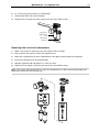
Connecting and purging the air supply
!
CAUTION: Safety glasses must be worn.
1.
Connect a suitable pipe to the air supply.
2.
Before connecting the pipe to the inlet of the air regulator system, briefly switch on the air supply to
clear out any debris from the pipe.
3.
Connect one end of the 4 mm air pipe into the air regulator system.
4.
Cut the 4 mm pipe to length, ensuring that the length of the pipe is as short as possible to minimise
the drop in air pressure. Make a note of the installed pipe length.
5.
Temporarily, tape over the free end of the pipe, to ensure that no coolant or debris is allowed to enter
the pipe.
6.
Push the free end of the air supply pipe through the air spring adaptor.
7.
Before connecting the pipe to the inlet of the TRS1 system, briefly switch on the air supply to clear out
any debris from the pipe.
8.
Connect the free end of the pipe to the TRS1 system.
9.
Push the air spring adaptor up over the air fitting on the TRS1 system.
10. Switch on the air supply, and set the pressure according to the graph on page 7.
Air regulator system
Air outlet
TRS1
System
Cable conduit
Ø4 mm
air pipe
Purge air supply to dislodge debris from
pipework prior to connection as small particles
may block the air nozzle.
!
Air spring
protector
CAUTION: The air supply should be
permanently switched on otherwise
coolant may enter the TRS1.
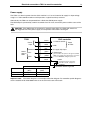
Electrical connections: TRS1 to machine controller
9
Power supply
The TRS1 can draw its power from the CNC machine’s 12 V to 24 V nominal dc supply. Its input voltage
range is 11 Vdc to 30 Vdc maximum and it presents a typical load of up to 45 mA.
Alternatively, the TRS1 can be powered from a Renishaw PSU3 power supply.
The SSR output is protected by a 50 mA resettable fuse. To reset, remove the power and the cause of the
fault.
!
CAUTION: If the SSR output is connected as normally open (N/O), the TRS1 will remain in a
non-triggered state if the power supply is interrupted or if the TRS1 is damaged.
CNC controller
TRS1
Power
input
{
Common
Status
output
SSR
N/C*
N/O**
brown
white
grey
green
yellow
black
+11 Vdc to 30 Vdc
0 Vdc
Power
to TRS1
I/O supply skip input
Probe input.
Connect either the yellow or the green, but DO
NOT connect both wires. Ensure the connection
is correct BEFORE cutting the spare wire.
screen
Controller protective earth also
referred to as ‘PE’, starpoint or
earthplate).
SSR contact
Status
*Normally closed **Normally open
(N/C)
(N/O)
Tool detected
Open
Closed
Tool not detected
Closed
Open
Controller reference ground
Important note: The above diagram is an example connection diagram. For controller specific diagrams
see the readme.txt file A-4010-0014 that is on the CD in the back of this book.
10
System set-up
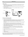
Range setting
1.
Position the reference tool at the point at which tool checking is to be performed. The reference tool
must be of known length and must be the smallest diameter tool that will be checked, as this will
provide the weakest reflected light signal.
2.
Measure the distance between the tool and the TRS1 front face (the range must be between 300 mm
[12 in] and 2 m [78 in]).
3.
Adjust the position of the receiver focus screw using a flat bladed screwdriver or a coin until the
pointer is opposite the required range.
Rx lens
Tx aperture
}
Signal
Strength
Bar graph
Status
display
90°
Receiver focus
screw
3 mm (0.12 in)
300 mm to 2 m
(12 in to 78 in)
Determine the checking position
1.
Rotate the reference tool at 1000 rpm.
2.
The end of the tool should be positioned approximately 3 mm (0.12 in) into the laser beam, refer to
the diagram above. Move the position of the TRS1 system relative to the tool side to side until the
highest number of displays in the bar graph are lit, (refer to the diagram on page 5).
Alternatively, place a piece of white paper behind the tool and centralise the shadow of the tool on the
red laser spot.
At 2 m (78 in) separation, it may only be possible to illuminate one red light on the bar graph display
with the smallest tool. The received signal will increase as the separation is reduced.
3.
Tighten the M6 mounting screw using a 10 mm AF spanner and a 5 mm AF hex driver to 8.3 Nm
(6.12 lbf. ft). Tighten the M4 mounting screws using a 3 mm AF hex driver to 2.6 Nm (1.92 lbf. ft) and
check that the TRS1 system has not moved.
4.
Note down the X and Y coordinates of the checking position. Those installations where the
TSR1 system does not move with the X or Y axes, only require the Z coordinate to be input.
5.
Move the tool position in Z only until the laser beam is only just shining on the tip of the tool.
Note down the Z coordinate.
6.
Add the tool length of the reference tool to the Z coordinate.
7.
Input this checking position into the memory locations accessed by the high-speed tool detection
program.
8.
The default checking position is 3 mm (0.12 in) from the tip of the tool, but this distance can be
modified by the user.
9.
It is the user’s responsibility to ensure that every tool can be detected at the checking position.
Note: If there is no access to the range setting screw when the system is mounted in the machine, the
range setting can be performed off the machine.
(continued on page 11)
System set-up
Receiver
focus screw
11
Flat bladed
screwdriver
Cleanliness
It is recommended that low pressure coolant washes off the TRS1 system on a regular basis during
cutting cycles. This will help to prevent the build-up of swarf or dried coolant on the receiver lens and can
easily be achieved by directing a coolant nozzle at the front of the TRS1 system.
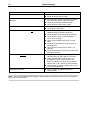
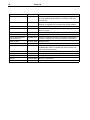
Troubleshooting
12
Fault
Rectification
No status light is lit.
● Check power connection.
● Check for damage of the cable.
Status display changes, but there is no skip at the
controller.
● Ensure that the correct relay contact is being
used (normally open or normally closed).
● Check the connection at the controller.
● Check that the correct skip is active.
There is no laser beam.
● Check the Tx aperture for blockage.
● Check power connection.
The TRS1 system fails to detect all good tools.
● Check that the spindle speed is set to
1000 rpm with no spindle override set.
● Check Rx lens for contamination or damage.
● Check that the range is between 300 mm
(12 in) and 2 m (79 in).
● Check system alignment in the X, Y and Z
axes.
● Check the tool position in the laser beam at
checking point.
● Check that the receiver focus screw is set
correctly.
● Check that the beam hits the tool at 90° to the
tool axis of rotation.
Fails to detect a specific good tool.
● Check that the tool gives enough good
reflection (the bar graph display must be lit).
● Check that the coolant on the tool is not
disrupting the beam’s sight the tool. If it is,
move to a cleaner part of the tool or remove
coolant with a spin, air blast or other method.
● If the tool does not have a solid centre, it may
not have been detected.
Dispersed laser beam.
● Clean Tx optics and identify source of
contamination.
Note: For the latest troubleshooting diagram, please refer to the Renishaw web site at www.renishaw.
com. Then search for TRS1
Specification
13
Application
High speed non-contact tool breakage detection of solid tools.
Working temperature
5 °C to 50 °C
Storage temperature
–10 °C to 70 °C
IP rating
The electronics are sealed to IPX8. The laser lens is sealed to IPX5 with air on.
Life
Tested to >1 million on/off cycles.
Tool diameter
See page 5.
Pneumatic supply
Ø4 mm air pipe, refer to the graph of recommended air pressure against air
pipe length on page 7.
Air supply to the TRS1 system must conform to ISO 8573-1: Air quality of class
1.7.2.
Weight
0.75 kg (1.65 lb) including 10 m of cable.
Mounting
Mounting bracket provided, with M4 mounting holes. Alternative mounting
arrangement provided by M4 holes in the product housing.
Range
See page 5.
Input voltage
11 Vdc to 30 Vdc
Current consumption
Typically less than 45 mA.
Cable
5 core plus screen cable. Each core 18/0.1 insulated.
Ø5.0 (0.20 in) x 10 m (32 ft).
Output
Solid state relay (SSR) normally open/normally closed contact max. 40 mA
(fused at 50 mA), refer to page 9.
14
Maintenance - TRS1 system
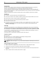
Introduction
The TRS1 system requires minimal maintenance, having been designed to operate as a permanent
fixture on a CNC machining centre in an environment of hot metal chips and coolant.
Only the maintenance routines described in this guide should be undertaken. Further dismantling and
repair of Renishaw equipment is a highly specialised operation and must only be carried out at authorised
Renishaw service centres.
Equipment requiring repair, overhaul or attention under warranty should be returned to your supplier.
Guidelines
● The TRS1 is a precision tool and must be handled with care.
● A low pressure coolant wash should be used during cutting cycles to keep the TRS1 clear of swarf.
● Ensure that the system is firmly secured to its rigid mounting.
● Do not allow excessive waste material to build up around the system.
● Keep electrical contacts clean.
● A continuous stream of clean air protects the TRS1 system. Approximately every 3 months, inspect
the optics for contaminants. The service interval may be extended or reduced dependent upon
experience, refer to page 7.
Cleaning
Cleaning may be required if the air to the TRS1 becomes contaminated or if the system is left with the
air off when coolant is present. Excessive contamination will block the laser beam and prevent the TRS1
from functioning. In this condition, the STATUS display will not change state when a good tool is checked.
If contamination is suspected, identify the cause and rectify the problem before cleaning the system. If
necessary, change the air pipe, refer to page 7.
If the receiver lens is contaminated, it should be cleaned, refer to page 14.
Equipment required
● Pin spanner.
● Solvent cleaner plus, RS No. 266-0856 (recommended) or isopropyl alcohol.
● Dust remover clean air spray (RS No. 846-698).
● 2 × wrapped polyester swabs (RS No. 408-1794).
!
CAUTION: Before removing the air cap, switch off electrical power to avoid exposure to the laser
beam.
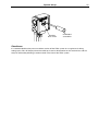
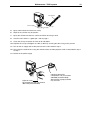
Cleanse the TRS1 system as follows:
1.
Make a note of the air supply pressure, then switch off the air supply and power supply.
2.
Remove the air cap from the transmitter using the pin spanner provided.
3.
Switch on the air supply and increase the pressure to purge out coolant that may be present in the
pipe work.
4.
When no further coolant is emitted, switch off the air supply.
(continued on page 15)
Maintenance - TRS1 system
15
Pin spanner
Power supply
Air cap
Air supply
5.
Spray solvent cleaner into the lens cavity.
6.
Wipe out any oil that may be present.
7.
Spray the solvent onto the lens surface and clean off using a swab.
8.
Check to see if there is a good spot - refer to page 7.
9.
Clean the air cap to remove all traces of oil and debris.
10. Replace the air cap and tighten to 2 Nm (1.48 lbf.ft), ensuring that the O-ring seal is present.
11. Turn on the air supply and set the pressure to the value noted in step 1.
12. Also, clean the receiver lens using the solvent cleaner and the polyester swab as described in step 5
to step 7.
13. Switch on the power supply.
Polyester swab
RS Components Ltd. part number
408-1794 (recommended)
Cleaning solvent RS
Components Ltd. part number
266-0856 (recommended).
Alternatively, isopropyl alcohol
may be used.
16
Maintenance – air regulator unit
Note: The following procedure applies to the air regulator system M-2253-5120, which is available from
Renishaw.
Checking the liquid level
Regularly check the level of the accumulated liquid in each of the filter bowls. It is important that the level
is kept below the filter element.
Draining the liquid
Drain the liquid that has accumulated in the filter bowl as follows:
1.
Make a note of the air supply pressure, then switch off the air supply. A quantity of liquid will drain
from the bowl.
2.
Switch on the air supply and set the pressure to the value noted in step 1.
3.
Repeat steps 1 and 2 until the bowls are empty.
Air pressure
adjusting knob
Air pressure
regulator and
filter system
Oil removal
filter system
Filter bowl
drain outlet
Removing and refitting filter elements
Regularly inspect the filter elements. They should be replaced when dirty or wet and at least once each
year. Do this as follows:
1.
Make a note of the air supply pressure, then switch off the air supply.
2.
Unscrew the filter bowl by hand.
3.
Remove the O-ring from the recess in the filter bowl. Discard the O-ring.
4.
Unscrew and remove the filter element.
5.
Fit the replacement filter and, where applicable, the O-ring. These are shown in dotted box A in the
figure on the next page.
(continued on page 17)
Maintenance – air regulator unit
6.
Fit a new O-ring into the recess in the filter bowl.
7.
Refit the filter bowl and screw hand tight.
8.
Switch on the air supply and set the pressure to the value noted in step 1.
Air pressure
regulator filter
bowl
Oil removal
filter bowl
Replacing other service kit components
1.
Make a note of the air supply pressure, then switch off the air supply.
2.
Using a 38 mm AF spanner, remove the regulator head.
3.
Remove the components (shown in dotted box B in the figure) from the body of the regulator.
4.
Fit the new components to the regulator body.
5.
Refit the regulator head and tighten to 7.7 Nm (5.7 Ibf.ft).
6.
Switch on the air supply and set the pressure to the value noted in step 1.
Note: Items shown within dotted boxes A and B are included in the air filter service kit obtainable from
Renishaw (see the parts lists on page 18).
A
B
17
18
Parts list
Type
Part number
Description
TRS1
A-4178-0400
TRS1 assembly, 10 m cable, mounting bracket, pin
spanner, product documentation and software CD, laser
warning sign
TRS1 kit
A-4178-1000
Contains all the items as per kit A-4178-0400 plus cable
conduit, air regulator, 25 m air pipe and air pipe conduit
Pin spanner
P-TL09-0005
Used for removing air cap
Air assembly kit
A-2253-5120
Air regulator with 2 x Ø4 mm air fittings and gauge, 25 m x
Ø4 mm air pipe
Air filter service kit
P-FI01-S002
Service kit for air regulator - parts for both filter bowls
Deluxe air filter
P-FI01-0008
Air regulator with blocked filter indication and auto drain
Product documentation
and software CD
H-2000-5254
Contains installation and user instructions, programming
manuals, software and software installation instructions
Cable conduit
P-CF01-0001
Sold per metre
Air pipe
P-PF26-0010
25 m x Ø4 mm black nylon tube
PSU3
A-2019-0018
PSU3 power supply system (for details see data sheet
H-2000-2200, which is available from the Renishaw web
site at www.renishaw.com)
Air pipe conduit
M-2253-0207
2 m x Ø7 mm stainless steel air pipe protector
Cable gland
P-CF02-0001
Cable gland for cable conduit
Cable gland
P-CA61-0054
Cable gland (domed) for air pipe conduit
Locknut
P-NU09-0016
M16 x 1.5 mm locknut
Air cap
A-4178-0440
Replacement air cap
Renishaw plc
New Mills, Wotton-under-Edge,
Gloucestershire, GL12 8JR
United Kingdom
T +44 (0)1453 524524
F +44 (0)1453 524901
E [email protected]
www.renishaw.com
For worldwide contact details,
please visit our main website at
www.renishaw.com/contact
*H-2000-5254-02*