1
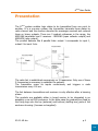
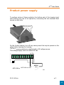
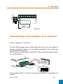
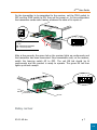
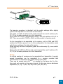
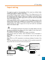
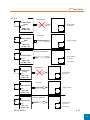
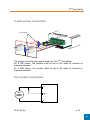
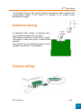
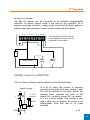
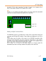
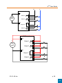
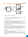
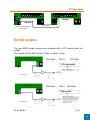
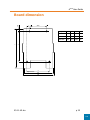
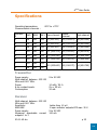
ARF20
Digital Status transfer
User Guide
No part of this document may be reproduced or transmitted (in electronic or
paper version, photocopy) without Adeunis RF consent.
This document is subject to change without notice.
All trademarks mentioned in this guide are the property of their respective
owner.
ADEUNIS RF
283, rue Louis Néel
38920 Crolles
France
Phone
Fax
+33 (0)4 76 92 07 77
+33 (0)4 76 08 97 46
Ref. 05-11-V4-tcx
ARF20 User Guide
Table of contents
About this document......................................................................... 2
Declaration of conformity ................................................................. 3
Presentation...................................................................................... 4
Product power supply ....................................................................... 5
Associating a transmitter to a receiver ............................................. 6
Open collector receiver.......................................................................6
Relay reciver .....................................................................................7
Memory clear on ARF6189 receiver .....................................................9
Memory clear on ARF6678 receiver .....................................................9
Input wiring .................................................................................... 10
3-wire sensor connection.................................................................. 12
Dry contact connection..................................................................... 12
Antenna wiring................................................................................ 13
Output wiring.................................................................................. 13
Binary outputs ................................................................................. 14
Validity output on ARF6189 .............................................................. 15
Relay output connection................................................................... 16
Relay output connection................................................................... 17
Validity output on ARF6678 .............................................................. 19
Synchronised mode......................................................................... 20
Serial output ................................................................................... 21
Board dimension ............................................................................. 22
Specifications .................................................................................. 23
05-11-V4-tcx
p1
ARF20 User Guide
About this document
This guide describes the ARF20 devices, their options and accessories.
05-11-V4-tcx
p2
TOP
ARF20 User Guide
Declaration of conformity
Manufacturer’s name:
Manufacturer’s address
ADEUNIS R.F.
Parc Technologique PRE ROUX IV
283 rue Louis NEEL
38920 CROLLES - FRANCE
declares that the product if used and installed according to the user guide available on
our web site www.adeunis-rf.com
Product Name:
Product Number(s):
ARF20
ARF6188B / ARF6189B /ARF6678B
Product options:
Complies with the RTTE Directive 99/5/EC:
EMC:
conformity is proven by compliance to the harmonized standard
EN 301-489
Safety:
conformity to the standard EN 60950-1/2001
Radio:
conformity is proven by compliance to harmonized standard EN
300-220 covering essential radio requirements of the RTTE directive.
Exposure to radio frequency signals according to the council recommendation
1999/519/EC on the limitation of exposure of general public to electromagnetic field.
es:
- Conformity has been evaluated according to the procedure described in
Annex III of the RTTE directive.
- Receiver class (if applicable): 3.
Crolles, November 6th, 2007
VINCENT Hervé / Quality manager
Download of the user guide
Thank you for having chosen the ADEUNIS RF products.
9
9
User guides can be uploaded directly on our web site www.adeunis-rf.com
Index
Products
Paragraph Modems > Status transfer
Print version available upon request
Tel : +33 4 76 92 07 77
Email : [email protected]
05-11-V4-tcx
p3
TOP
ARF20 User Guide
Presentation
The ARF20 system enables logic states to be transmitted from one point to
another. It is a one-way system: the transmitter transmits these states by
radio channel and the receiver decodes the messages received and restores
them on binary outputs. There are 3 product references in the range, the
ARF6188 transmitter and 2 receivers - ARF6189 (open collector output) and
ARF6678 (relay output).
The product behaves like 8 parallel links: output 1 corresponds to input 1,
output 2 to input 2 etc.
The radio link is established successively on 3 frequencies. Only one of these
3 frequencies is necessary to establish the outputs.
The transmitter scans its inputs continuously and triggers a radio
transmission every 100 ms.
The link between transmitters and receivers is only effective after a learning
phase.
The products are available either in board version to be integrated in an
assembly or as an IP65 enclosure. In the latter case the products are fixed by
the fixing lugs onto the top (antenna) and bottom (stuffing box) parts of the
enclosure housing (4 screws not supplied).
05-11-V4-tcx
p4
TOP
ARF20 User Guide
Product power supply
To perform wiring of these products, the bottom part of the housing (part
with stuffing box) has to be opened by unscrewing the two stainless steel
screws on each side.
Removeles
Retirer
the
visscrews
de la partie
from
avecpart
the
presse
with étoupe
stuffing box
On the 4-relay receiver, turn off any mains power that may be present on the
relays before opening the housing.
The ARF20 range products are supplied with a DC voltage source.
This voltage supply must not exceed 30 Vdc.
+V 0V
+
6188 et 6189
ARF 6188 andARF
6189
05-11-V4-tcx
ARF20
power
ou
p5
TOP
ARF20 User Guide
0V
+V
+
ARF20
power
ARF 6678
Associating a transmitter to a receiver
Open collector receiver
The red ON led flashes twice and the green RX led is not lit, the product is
correctly supplied but there is no transmitter associated to the receiver and
the product cannot operate.
On the receiver, set the switch marked AP to ON to switch to learning mode.
The red led flashes.
0V
12 to 30V DC
power supply
+VDC
ON LED
RX LED
1
ADD
2 3
AP
ON
Set the switches ADD 1, 2 and 3 to the same positions on the transmitter and
receiver.
05-11-V4-tcx
p6
TOP
ARF20 User Guide
On the transmitter to be associated to the receiver, set the TR00 switch to
OFF and the SYNC switch to ON, then set the power on. In this configuration
the transmitter sends radio frames, whatever the state of its inputs is.
NO
NC
ON
SYNC
1
ADD
2 3
TR00
ON
1 : NC/NO
2 : SYNC
ON : autonomous operation
OFF : controlled operation
9 to 30V DC
power supply
After a few seconds, the green led on the receiver lights up continuously and
the transmitter has been memorised. Stop transmission and, on the receiver,
switch the learning switch AP to OFF. The red ON led should be lit
continuously and the product is ready to operate. The green RX led then
lights up at each receipt.
1
ADD
2 3
AP
ON
ON LED
RX LED
Relay reciver
05-11-V4-tcx
p7
TOP
ARF20 User Guide
RX LED
N
1
2
3
LH
OFF
The learning procedure is identical, but the switch settings differ slightly
(perform the operations in the order set out below):
Set switch #1 (N/P) to ON (normal mode) and set the next 3 switches (C1,
C2, C3) to the same positions as on the transmitter.
Move switch #1 to OFF (programming mode), then set switches #2 to 5 to
OFF. Then move switch 2 (AP) to ON to set the product to learning mode.
On the transmitter to be associated to the receiver, set the TR00 and SYNC
switches to ON then power it on. In this configuration the transmitter sends
radio frames whatever the state of its inputs.
When learning has been completed (green led continuously lit), move switch
#2 to OFF.
Reset switch #1 (N/P) to ON (normal mode) and set the next 3 switches (C1,
C2, C3) to the same positions as on the transmitter.
NOTES:
An infinite number of receivers can be associated to a transmitter. Inversely
several transmitters can be associated to a receiver provided that
transmissions are extremely rare (TR00 must be set to ON).
There can be several pairs of ARF20 's in parallel on the same site. For this,
they must not operate on the same channel. In this case choose addresses
separated by 3, e.g. 1 (OFF, ON, ON) and 4 (ON, ON, OFF).
05-11-V4-tcx
p8
TOP
ARF20 User Guide
1
Address 1
2 3 AP
Address 7
1 2 3 AP
Address 4
1 2 3 AP
ON
ON
ON
or
or
EFF
Memory clear on ARF6189 receiver
ON
To clear all the recorded serial numbers from
the receiver memory, the two pads to the left of
the red led have to be short-circuited. The red
led then flashes. Maintain the short-circuit until
the green led lights up: the memory has then
been cleared.
RX
Memory clear on ARF6678 receiver
Set switch #1 to OFF (programming mode), then set switches #2 to 5 to
OFF. Then move switch #3 to ON (EF) to run the clear procedure.
After 6 seconds, the memory clear has been completed, the green led is lit
continuously. Move switch #3 to the OFF position.
Reset switch #1 (N/P) to ON (normal mode) – the red led flashes indicating
that the product can no longer operate.
05-11-V4-tcx
p9
TOP
ARF20 User Guide
Input wiring
The inputs are wired on the transmitter. All the inputs are defined either
normally open (NO) or normally closed (NC).
In NO mode (NO/NC on ON), an input is active if the voltage present on the
terminal block is greater than +Vsupply /2. If the input is not connected or is
at a voltage lower than Vsupply /2 the input is inactive. In this case, closing
of a contact between the power supply and an input will make the associated
relay on the receiver close.
In NC mode (NO/NC on OFF), an input is active if the voltage present on the
terminal block is lower than +Vsupply/2 or not connected. If the input is at a
voltage greater than Vsupply /2 the input is inactive. In this case, closing of a
contact between the power supply and an input will make the associated
relay on the receiver open.
!
Ì
The Vsupply/2 threshold is not precise. For greater safety a low level
should be considered if the voltage is less than Vsupply /3 and a high level if
the voltage is more than 2 Vsupply/3.
The presence of at least one active input triggers transmission.
When all the inputs are inactive, radio transmission can be interrupted or
maintained:
When TR00 is on ON, there is no transmission when all the inputs are
inactive.
When TR00 is on OFF, transmission is continuous whatever the state of the
inputs.
These two operating options are to be chosen with the product powered off:
they will be taken into account at the next power-up.
1, 2, 3 : Transmission channels
NO
NC
SYNC
4 : TR00
ON : Transmits 3 frames when all the
inputs are inactive, then switches to
stand-by.
OFF : Transmits continuously when all
the inputs are inactive.
ON
1
1 : NC/NO
2
3
TR00
ON
2 : SYNC
see paragraph 8
05-11-V4-tcx
p 10
TOP
ARF20 User Guide
cf. § 8
ARF20 transmitter
+V
No transmission
ARF20 receiver
8 inactive inputs
(open)
Input n
All the outputs
are inactive
TR00 = ON
NC/NO = ON
ARF20 transmitter
+V
Transmission
ARF20 receiver
At least 1 closed
input
Input n
Output n is active
TR00 = ON
NC/NO = ON
ARF20 transmitter
+V
Continuous transmission
ARF20 receiver
8 inactive inputs
All the outputs
are inactive
Input n
TR00 = OFF
NC/NO = ON
ARF20 transmitter
+V
Active safety
No transmission
ARF20 receiver
8 inactive inputs
(open)
Input n
All the outputs
are inactive
TR00 = ON
NC/NO = OFF
ARF20 transmitter
+V
Transmission
ARF20 receiver
At least 1 open input
Output n is active
Input n
TR00 = ON
NC/NO = OFF
ARF20 transmitter
+V
Continuous transmission
ARF20 receiver
8 inactive inputs
Input n
TR00 = OFF
NC/NO = OFF
05-11-V4-tcx
All the outputs
are inactive
Active safety
p 11
TOP
ARF20 User Guide
3-wire sensor connection
10 kΩ resistors
PNP
NPN
The sensors have the same power supply as the ARF20 transmitter.
For a PNP sensor, the product must be set to NO mode to transmit on
presence detection.
For a NPN sensor, the product must be set to NC mode to transmit on
presence detection.
Dry contact connection.
ARF20 transmitter
+V
+
DC
POWER
SUPPLY
Input
0V
05-11-V4-tcx
p 12
TOP
ARF20 User Guide
In NO mode closing of the contact triggers transmission which activates the
corresponding output. In NC mode it is opening of the contact which
activates this output.
Antenna wiring
In daughter board version, an antenna has to be added to obtain correct
communication between the products.
This antenna should be a wire with a length of ¼ wave i.e. about 17 cm.
This length is that which has to extend outside the housing if the latter is
metallic.
This antenna can be located remotely by using a coaxial cable with its braid
stripped over the last 17 centimetres.
Output wiring
05-11-V4-tcx
p 13
TOP
ARF20 User Guide
The outputs are wired on the receiver. They are of the P open collector type,
i.e. when an output is active the voltage on the terminal block is that of the
power supply. In other words an output acts like a switch one terminal of
which is connected to the +Vdc and the other terminal being the output
connector:
+supply
+supply
=
output
output
The receiver also has an output indicating data validity (S).
Binary outputs
Output 1 copies the state of input 1, output 2 that of input 2, etc. On outputs
1 to 7 the maximum current absorbed is 100 mA. On output 8 this current
increases to 1 A.
On the 4-relay receiver, the relays are the image of channels 1 to 4 when
switch #5 (LH) is set to OFF, and the image of channels 5 to 8 when it is set
to ON.
Relay wiring:
1 2 3 4 5 6 7 8 S +V 0V
The ARF20 receiver power supply
must be compatible with the
characteristics of the relay.
DIODE
RELAY
+
ARF20
supply
The freewheel diode is
necessary to preserve the
product lifetime.
05-11-V4-tcx
p 14
TOP
ARF20 User Guide
Wiring to a controller:
The ARF 20 receiver can be connected to an industrial programmable
controller. An active channel sends a low level to the controller. On a
negative input logic controller, reading of the channel will be direct, and on a
positive input logic controller, reading of the channel will be inverted.
1 2 3 4 5 6 7 8 S +V 0V
The controller and ARF20 receiver
power supplies must have their 0V
connected to one another.
R
CONTROLLER
+
+
CTRL.
ARF20
supply
supply
Validity output on ARF6189
This is an Open Collector output marked S on the terminal block.
Output S wiring
5V
+ 12 V
(example)
S
100 kΩ
S
05-11-V4-tcx
It is at 0V when the receiver is receiving
correctly and at high level when receipt is bad.
The red led furthest to the right, behind the
terminal block, indicates the state of this
output: On - receipt is correct, Off - no receipt.
It is not a linear output. This enables a zero
output state due to absence of receipt to be
differentiated from that due to no input
activated.
p 15
TOP
ARF20 User Guide
1
All receipts are correct, or only one is
missing:
The safety output remains inactive.
Outputs
Receipts
106 ms
SEC output
2
Two consecutive receipts at least are missing:
The safety output is activated.
At the third missing receipt, the outputs become inactive.
Outputs
Receipts
SEC output
Relay output connection.
The ARF6678 receiver is provided with 3 relays with a single NO contact and
one relay with NO and NC contacts. These relays are designed to cut 12A in
250V.
These relays copy the state of the inputs of an ARF6188 transmitter after
learning of this transmitter has been performed. Depending on the position
05-11-V4-tcx
p 16
TOP
ARF20 User Guide
of switch #5 the relays reproduce the state of inputs 1 to 4 (switch #5 on
OFF) or the state of inputs 5 to 8 (switch #5 on ON).
NB
If relay 1 or 3 is used for the safety output, it no longer copies the associated
input but its closing indicates the quality of the radio link.
11
12
21
22
33
31
32
41
42
+
1 2
3
4
5
Copie 5 à 8
Copies 5 to 8
Copie1 1
Copies
to à4 4
RX
Relay output connection.
The ARF6678 receiver is provided with 3 relays with a single NO contact and
one relay with NO and NC contacts. These relays are designed to cut 12A in
250V.
These relays copy the state of the inputs of an ARF6188 transmitter after
learning of this transmitter has been performed. Depending on the position
of switch #5 the relays reproduce the state of inputs 1 to 4 (switch #5 on
OFF) or the state of inputs 5 to 8 (switch #5 on ON).
NB: If relay 1 or 3 is used for the safety output, it no longer copies the
associated input but its closing indicates the quality of the radio link.
05-11-V4-tcx
p 17
TOP
ARF20 User Guide
Ph.
N
ARF20 receiver
+V
+
Output 1
24VDC
SUPPLY
Output 2
12
11
22
21
31
0V
Output 3
Output 4
32
33
42
41
ARF20 receiver
+V
+
Output 1
24VDC
SUPPLY
Output 2
11
22
21
31
0V
Output 3
Output 4
05-11-V4-tcx
12
32
33
42
41
p 18
TOP
ARF20 User Guide
ARF20 4-relay
receiver
SW1-5 = OFF
The outputs are
the image of
inputs 1 to 4
ARF20 transmitter
+V
8 active inputs
Input n
ARF20 4-relay
receiver
SW1-5 = ON
The outputs are
the image of
inputs 5 to 8
Validity output on ARF6678
On this receiver the information is available as an option on a relay. This can
be on relay 1 (NO) or relay 3 (NO/NC), as required.
Safety validation on relay 1
Set switch #1 to OFF (programming mode), then set switches #2 to 5 to
OFF, and then move switches #4 (SE) and 5 (14) to ON.
Reset switch #1 (N/P) to ON (normal mode) and set the next 3 switches (C1,
C2, C3) to the same positions as those of the transmitter (ADD 1, 2 and 3).
Safety validation on relay 3
Set switch #1 to OFF (programming mode), then set switches #2 to 5 to
OFF. Then move switch #4 (SE) to ON and switch #5 (14) to OFF.
Reset switch #1 (N/P) to ON (normal mode) and set the next 3 switches (C1,
C2, C3) to the same positions as those of the transmitter (ADD 1, 2 and 3).
Safety disable
Set switch #1 to OFF (programming mode), then set switches #2 to 5 to
OFF. Then move switch #4 (SE) to OFF.
Reset switch #1 (N/P) to ON (normal mode) and set the next 3 switches (C1,
C2, C3) to the same positions as those of the transmitter (ADD 1, 2 and 3).
05-11-V4-tcx
p 19
TOP
ARF20 User Guide
Synchronised mode
This mode enables two-way links to be achieved with 2 ARF20 pairs. In this
case the return link is dependent on the outgoing link.
Common power supply ground
RX
ARF20
(6189 or
6678)
TX
ARF20
(6188)
§
Synchronisation signal
RX
ARF20
(6189 or
6678)
¦
Signal de synchronisation
TX
ARF20
(6188)
The link (2) only works if link (1) is present. Take care over transmission in
rest state.
Setting transmitter to synchro mode
A transmitter is set to synchro mode by setting switch #2 marked SYNC to
OFF.
Then connect the synchro output of the link (1)
receiver (pad to be soldered marked "sync" /
ARF6189 or "2" / ARF6678) to the TRIG input
Synchro mode
terminal of the link (2) receiver.
control
SYNC
<
OUTPUT 1 TO 8
>
S +V 0V
SYNC
TRIG
<
INPUT 1 TO 8
>
+V 0V
ARF6188D
ARF6189D
Connect the power supply 0V
to one another
05-11-V4-tcx
To ARF6188 transmitter
TRIG terminal
p 20
TOP
ARF20 User Guide
0V
+V
11 12 21 22 33 31 32 41 42
TRIG
<
INPUT 1 TO 8
>
+V 0V
ARF6188D
(2)
ARF6678B
Connect the power supply 0V
to one another
To ARF6188 transmitter
TRIG terminal
Serial output
The two ARF20 range receivers are equipped with a TTL format serial link
output.
The format is fixed: 9600 bauds / 8 bits, no parity 1 stop.
05-11-V4-tcx
p 21
TOP
ARF20 User Guide
x
36.6
Copper
l
ARF6188
87
7.75 67.06 52.84
x
y
ARF6189
87
7.49 67.82 52.84
ARF6678
122
-6.6
105.3
z
23
y
l
3.81
Board dimension
z
61
64
05-11-V4-tcx
p 22
TOP
ARF20 User Guide
Specifications
Operating temperature:
Communication channels :
-20°C to +70°C
ADDRES
S
SW3
SW2
SW1
Low channel
Middle
channel
High channel
1
ON
ON
OFF
2 (433.150)
23 (433.675)
46 (434.250)
2
ON
OFF
ON
5 (433.225)
26 (433.750)
49 (434.325)
3
ON
OFF
OFF
8 (433.300)
29 (433.825)
52 (434.400)
4
OFF
ON
ON
11 (433.375)
32 (433.900)
55 (434.475)
5
OFF
ON
OFF
14 (433.450)
35 (433.975)
58 (434.550)
6
OFF
OFF
ON
17 (433.525)
40 (434.100)
61 (434.625)
7
OFF
OFF
OFF
0
ON
ON
ON
20 (433.600)
43 (434.175)
64 (434.700)
Transmitter
Power supply:
Multi-channel between 433.125
MHz and 434.7 MHz.
Power:
8 dry contact inputs.
Consumption:
9 to 30 VDC
10 mW / 50 Ω.
Zin > 50 kΩ.
30 mA.
Receiver
Multi-channel between 433.125
MHz and 434.7 MHz.
Sensitivity:
ARF6189 :
Power supply:
Maximum absorbable current
outputs 1 to 7:
05-11-V4-tcx
better than 1.2 µV.
8 open collector outputs:VCE max. 30 V.
9 to 30 VDC
100 mA
p 23
TOP
ARF20 User Guide
Maximum absorbable current
output 8:
Receipt validity output.
ARF6678: 4 relay outputs:
Power supply:
NO contact on outputs 1, 2 or 4
NO/NC contacts on output 3
Receipt validity output:
Consumption:
Conversion
Refresh period:
(up to 320 ms when
establishing the link)
1 A.
10A / 250V.
15 to 30 VDC
disabled, or on relay 1 or relay 3, as
required.
53 mA excluding output
106 ms.
Dimensions
6188B and 6189B IP65 chip:
6678B IP65 chip:
Distance between fixing points
6188B and 6189B : 4 holes
diam. 4 to 92 x 61 mm
Distance between fixing points
6678B: 4 holes diam. 4 to 92 x
96 mm
104 x 300 x 35 mm
104 x 335 x 35 mm
References
ARF6188A: ARF20 transmitter, board version.
ARF6188B: ARF20 transmitter in IP65 chip version.
ARF6189A: 8 open collector ARF20 receiver, board version.
ARF6189B: 8 open collector ARF20 receiver in IP65 chip version.
ARF6678A: 4-relay ARF20 receiver, board version.
ARF6678B: 4-relay ARF20 receiver in IP65 chip version.
ARF03: Antenna kit for the ARF618xA and ARF6678A in board
version.
05-11-V4-tcx
p 24
TOP