1
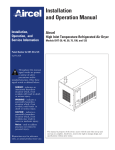
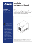
SM70 Monitor User Guide Aeroqual Ltd, March 2013 www.aeroqual.com 1 MRK-D-0017 V1 WWW.TEESING.COM | +31 70 413 07 50 Contents Contents ................................................................................................................................................. 2 For Your Safety ...................................................................................................................................... 3 1. SM70 Components........................................................................................................................ 3 2. About Your Monitor / Controller .................................................................................................. 3 3. Getting Started .............................................................................................................................. 4 3.1. Installation................................................................................................................................ 4 3.2. Turning the monitor on and off ................................................................................................ 4 3.3. Warming up ............................................................................................................................. 4 3.4. External Wiring through the Cable Gland ................................................................................ 4 4. Input and Output signals ............................................................................................................. 5 4.1. Sensor Board Switches ........................................................................................................... 5 4.1.1. ZERO CAL ........................................................................................................................ 5 4.1.2. RESET .............................................................................................................................. 5 4.1.3 SPAN ............................................................................................................................... 5 4.1.4 RELAY Dipswitch............................................................................................................. 5 4.2. Sensor Board LEDs ................................................................................................................. 5 4.2.1. Status LED (Normal and Failure modes) ........................................................................ 5 4.2.2. Relay LED ........................................................................................................................ 5 4.3. Relay........................................................................................................................................ 5 4.3.1. Setting the Relay and Alarm Set Point ............................................................................ 7 4.3.2. Wiring to the relay ............................................................................................................ 7 4.4. 0-5VDC Analog output ............................................................................................................. 8 4.5. Serial communications ............................................................................................................ 8 5. Calibration ..................................................................................................................................... 9 5.1. Zero Calibration Procedure ..................................................................................................... 9 5.2. Span Check Procedure ........................................................................................................... 9 6. Maintenance .................................................................................................................................. 9 6.1. Replacing the Sensor Board.................................................................................................. 10 7. Troubleshooting.......................................................................................................................... 11 8. Specifications ............................................................................................................................. 12 Appendix 1 ........................................................................................................................................... 13 Copyright ........................................................................................................................................... 13 Terms and Conditions ....................................................................................................................... 13 Statements of Compliance ................................................................................................................ 13 Appendix 2 ........................................................................................................................................... 14 Serial Communication Protocols ....................................................................................................... 14 RS232 Protocol ................................................................................................................................. 14 RS485 Protocol ................................................................................................................................. 16 Aeroqual Ltd, March 2013 www.aeroqual.com 2 MRK-D-0017 V1 WWW.TEESING.COM | +31 70 413 07 50 For Your Safety The Aeroqual SM70 Monitors are used to monitor ambient gas concentrations. Aeroqual does not guarantee user safety. In hazardous environments, an appropriate Health and Safety plan should be in place. The SM70 contains no user serviceable parts. Return unit to Aeroqual or your Distributor for servicing. Use only approved accessories. When connecting to any other device, read the appropriate user guide for detailed safety instructions. Do not use the SM70 in or near flammable fuel or chemicals. 1. SM70 Components The following components are supplied with the SM70 Monitor: SM70 Monitor 12 VDC AC/DC adaptor Enclosure mounting brackets User guide Please check that all these components have been supplied and contact your dealer or Aeroqual on email at: [email protected] if any of the components are missing. 2. About Your Monitor / Controller The Aeroqual SM70 Monitor is designed for monitoring of gases in an indoor environment. It is supplied with three different versions of firmware which control the internal relay in different ways depending on the application (see table below). The version installed is indicated on an internal label under lid. Please ensure you have the version you require. Table 1: SM70 firmware versions and description Firmware Description AA Alarm above: the relay is energised when the reading is above the setpoint AB Alarm below: the relay is energised when the reading is below the setpoint. C10 Control: the relay is energised to control the gas concentration to a band within +/10% of the setpoint. The SM70 is supplied pre-drilled with a cable gland to facilitate connection to the relay and communication terminations. The SM70 is a sensitive instrument and should not be exposed to steam, water/chemical spray or high levels of dust. Doing so may significantly shorten the life of the sensor. Aeroqual Ltd, March 2013 www.aeroqual.com 3 MRK-D-0017 V1 WWW.TEESING.COM | +31 70 413 07 50 3. Getting Started 3.1. Installation Wall mounting brackets are provided and fit into the holes at each corner of the enclosure - see picture below. Concealed, tamperproof screw fixing through the corner posts of the enclosure is also possible without using the fixing brackets. The SM70 should be installed at a location that is free from contaminants that might affect the performance of the sensor module. 3.2. Turning the monitor on and off The SM70 is designed to run constantly. To turn the monitor on simply plug in the 12 VDC cable from the AC adaptor and turn on at the mains switch. To turn the SM70 off, switch it off at the mains switch. 3.3. Warming up The SM70 sensor sometimes requires warming up to achieve a stable baseline. It has an inbuilt warming cycle of about 3 minutes but may need longer to under certain conditions. If it is the first time the monitor has been powered on it is recommended to run it for a period of a few hours before use. 3.4. External Wiring through the Cable Gland The SM70 enclosure is pre-drilled and fitted with a cable gland to facilitate a cable connection to the SM70 relay and data output connectors. Cable gland for RS232 or RS485 connection Aeroqual Ltd, March 2013 www.aeroqual.com 4 MRK-D-0017 V1 WWW.TEESING.COM | +31 70 413 07 50 4. Input and Output signals 4.1. Sensor Board Switches The SM70 sensor board contains a number of buttons, LEDs and a dipswitch which are accessible once the sensor board is detached from the lid. See section 6.0 4.1.1. ZERO CAL This button activates a zero calibration routine on the sensor. It should only be pushed when you are performing a zero calibration. 4.1.2. RESET This button resets the SM70 microcontroller without needing to remove the power from the SM70. 4.1.3 SPAN This button will change the span calibration of the SM70 and should not be activated for any reason. 4.1.4 RELAY Dipswitch The Relay dipswitch changes the set point for activation of the SM70 relay. See section 4.3 for a description of the concentration set points. 4.2. Sensor Board LEDs 4.2.1. Status LED (Normal and Failure modes) The status LED glows green and is located on the Sensor board. At start up, the Status LED will flash 2 to 6 times at an interval of 0.5 seconds. During the 3 to 10 minute warm-up time, the Status LED will flash at an interval of 2 seconds. Normal status: Sensor Failure: Constant on Flashes quickly at an interval of 0.3 seconds. 4.2.2. Relay LED The relay LED glows red and is also located on the Sensor board. This LED comes on when the relay is energised. 4.3. Relay The SM70 sensor module can be used as a simple gas sensitive relay switch to control devices or activate alarms using the on-board relay. The relay has COM (common), NO (normally open), NC (normally closed) contacts. Three SM70 relay control firmware programs are available: AA, AB, C10. The user should have specified the program installed prior to delivery. The relay logic of the three firmware versions is described below. External equipment connected to the on-board relay should be wired appropriately to the normally open or normally closed contacts. AA Alarm-Above: the relay is programmed to energise above the selected set point. Typical applications are health and safety alarm/warning systems or switching external equipment on and off. This is the default software. Aeroqual Ltd, March 2013 www.aeroqual.com 5 MRK-D-0017 V1 WWW.TEESING.COM | +31 70 413 07 50 Relay closed (energised) Set Point Relay open (de-energised) When gas concentration is rising from below the “Set Point”, relay de-energised (relay NO=open, NC=closed) When gas concentration rises and reaches the “Set Point”, relay is energised (relay NO= closed, NC = open) When gas concentration drops and reaches the “Set Point”, relay de-energised (relay NO=open, NC=closed) AB Alarm-Below: the relay is programmed to energise below the selected set point. Typical applications are fail safe warning systems or controlling a gas generator. Relay open (de-energised) Set Point Relay closed (energised) When gas concentration is rising from below the “Set Point”, relay energised (relay NO= closed, NC = open) When gas concentration rises and reaches the “Set Point”, relay is de-energised (relay NO= open, NC = closed) When gas concentration drops and reaches the “Set Point”, relay energised (relay NO=closed, NC=open) C10 The relay is programmed to open and close around the selected control set point ±10% to create a “control band”. Typical application is for maintaining a specific gas concentration between user defined levels through the control of an external device e.g. ozone generator. Upper Limit 110% Relay open (de-energised) Relay closed (energised) 100% Software Dead Band of ±10% of set point Set Point 90% Lower Limit Aeroqual Ltd, March 2013 www.aeroqual.com 6 MRK-D-0017 V1 WWW.TEESING.COM | +31 70 413 07 50 When the gas level is rising from below “Lower Limit” to “Upper Limit”, relay is energised, (NO=closed, NC = open) When gas level is falling from above “Upper Limit” to “Lower Limit”, relay is de-energised (NO=open, NC = closed) 4.3.1. Setting the Relay and Alarm Set Point The Relay Set Point can be altered by adjusting the set-point dip-switches as shown below. The Relay Set Point is factory set (unless otherwise specified) to OFF-ON-OFF-ON. The setpoint levels for different dipswitch settings are provided below for some sensors. Contact Aeroqual if your sensor is not listed. Table: Dipswitch setpoint levels Relay dipswitch (1 2 3 4) O3 0-0.150 ppm O3 0-0.5 ppm O3 0-10ppm VOC 0-500 ppm VOC 0-25 ppm on on on on 0.000 0.000 0 0 0 off on on on 0.010 0.025 0.5 20 1 on off on on 0.020 0.050 1 40 2 off off on on 0.030 0.075 1.5 60 3 on on off on 0.040 0.100 2 80 4 off on off on * 0.050 0.125 2.5 100 5 on off off on 0.060 0.150 3 120 6 off off off on 0.070 0.175 3.5 140 7 on on on off 0.080 0.200 4 160 8 off on on off 0.090 0.225 4.5 180 9 on off on off 0.100 0.250 5 200 10 off off on off 0.110 0.300 6 250 12 on on off off 0.120 0.350 7 300 14 off on off off 0.130 0.400 8 350 16 on off off off 0.140 0.450 9 400 20 off off off off 0.150 0.500 10 500 25 * Factory default setting 4.3.2. Wiring to the relay If you require the SM70 be used to control a mains powered device you will need to include a separate mains rated relay. Mains equipment should only be wired by a certified electrician. Open up the SM70 enclosure and remove the PC board as detailed in section 6. Turn over the PCB board so that the underside is visible as shown below. Using the screw connector on the PC board, wire the desired external device to either the normally open or normally closed contacts as required for your application and firmware version. Feed the cable through the supplied cable gland to your external devices. Aeroqual Ltd, March 2013 www.aeroqual.com 7 MRK-D-0017 V1 WWW.TEESING.COM | +31 70 413 07 50 Diagram showing a method of connecting a SM70 to a mains powered device. EXTERNAL DEVICE e.g. O3 generator Insert jumper wire between Com and GND Insert diode in circuit to suppress back EMF Com GND NO V+ Diode IN4004 External relay must be suitably rated to switch the external load Operating voltage of relay coil must be 12 VDC L N E 240 VAC 4.4. 0-5VDC Analog output The gas concentration is available as a 0-5V signal at the 0-5V and AGND connectors on the screw terminal block. 0 volts = zero ppm and 5 V = designated range of sensor (for example, a 0-0.5 ppm O3 SM70 module would output 5V at 0.500 ppm ozone). The resolution of the analog signal is 8 bit. NOTE: the 0-0.150ppm O3 sensor analogue output is 1.5V at 0.150ppm (full scale). All other sensors output 5.0V at full scale. 4.5. Serial communications Gas concentration data is available on the RS232 and RS485 digital communication channels. The RS485 channel is 2-wire, the RS232 is 2-wire plus GND. Connection is via the screw terminal connectors on the sensor board. The communication protocols for these serial interfaces are provided in the Appendix. Please note: the RS232 serial protocol is a proprietary format and is not ASCII. Hence a terminal program cannot be used to communicate with the SM70. Aeroqual Ltd, March 2013 www.aeroqual.com 8 MRK-D-0017 V1 WWW.TEESING.COM | +31 70 413 07 50 5. Calibration The SM70 can be fully calibrated by replacing the old sensor board with a replacement SM70 sensor board with a multi-point calibration and new calibration certificate. Alternatively, a SM70 baseline calibration can be undertaken by the user following procedure 5.1. Always undertake a zero calibration before doing a span check. The SM70 span response can be checked by the user following procedure 5.2 In order to calibrate successfully the following equipment is needed: R42 Calibration Gas Humidifier (Aeroqual accessory) Inert tubing between regulator to R42 (eg PFA tubing) 0.5 LPM constant flow regulator (eg Calgaz regulator model 715, flow rate 0.5 LPM) Zero grade air cylinder or zero air generator Span gas in air cylinder or ozone source R42 calibration accessory 5.1. Zero Calibration Procedure 1. 2. 3. 4. 5. 6. 7. If necessary charge R42 Calibration Gas Humidifier with 5g of water with water syringe via water inlet. Connect zero air cylinder and regulator to R42 with tubing. Remove the lid of the SM70 and detach the sensor board to locate the “Zero Cal” button. Place the R42 outlet over the SM70 sensor. Flow zero air into R42 until the SM70 reading stabilises (about 10 minutes) Initiate Zero Calibration on the Aeroqual SM70 by pressing the button on the sensor PCB marked “zero cal” Zero air connected to R42 Wait 5 minutes for the process to be completed. 5.2. Span Check Procedure 1. 2. 3. 4. 5. If necessary charge R42 Calibration Gas Humidifier with 5g of water with water syringe via water inlet. Connect span gas cylinder and regulator to R42 gas inlet with tubing. Place the R42 outlet over the SM70 sensor Flow span gas air into R42 until the SM70 reading stabilises (typically 10 minutes) If the SM70 does not respond correctly then the sensor board should be replaced. 6. Maintenance The SM70 is designed to be a low maintenance instrument with no user serviceable components. It is recommended that the SM70 be zero and span checked at regular intervals (monthly if possible) to ensure on going responsiveness. The sensor board needs to be replaced with a calibrated board annually. Aeroqual Ltd, March 2013 www.aeroqual.com 9 MRK-D-0017 V1 WWW.TEESING.COM | +31 70 413 07 50 6.1. Replacing the Sensor Board Unscrew the four lid screws and remove lid. Unscrew sensor board using a 5.5mm hexa socket screwdriver and remove cabling. Keep the screws, nuts, washers and standoffs for re-use. Connect cabling to new sensor board and re-attach to enclosure lid. Connect new board Make sure board does not rest on connectors Place board in enclosure ensuring screws slide through both holes so board is resting on the plastic standoffs underneath Use 5.5mm Hexa Socket Screwdriver or Small Grip Pliers to tighten nuts. N/B: Remember to replace the brown washers. Use Flat Screwdriver to hold screw in place during tightening. Aeroqual Ltd, March 2013 www.aeroqual.com 10 MRK-D-0017 V1 WWW.TEESING.COM | +31 70 413 07 50 7. Troubleshooting A fault diagnosis table is given below. Please consult this in the first instance to help diagnose a suspected fault. If you are unable to find the fault in the table or the suggested remedy does not work, please contact Aeroqual’s Technical Support by sending an email to [email protected]. This automatically generates a ticket which will be acted upon by a Technical Support Person. Fault Possible causes Remedy No Power Power supply failure SM70 damaged Replace 12 VDC plug pack Replace sensor board Sensor failure (Status LED flashes quickly) Sensor needs warming up Air contaminated SM70 sensor damaged Run the SM70 for 24 hours in clean air Move SM70 to a clean environment Replace sensor board Reading high in clean air Insufficient warm up Air contaminated Sensor damaged Run the SM70 for 24 hours in clean air Move the sensor to clean air environment Replace sensor board Reading lower than expected Sensor correct Interferent gas present Sensor calibration incorrect Gas concentration is lower than expected. Do span check Do span check Reading higher than expected Sensor correct Interferent gas present Sensor calibration incorrect Gas concentration is higher than expected. Do span check Do span check Reading unstable Power supply unstable Local airflow is unstable EMF interference is high Replace power supply Shield unit from airflow Shield unit from interference. Aeroqual Ltd, March 2013 www.aeroqual.com 11 MRK-D-0017 V1 WWW.TEESING.COM | +31 70 413 07 50 8. Specifications Sensor type Sensor specifications Sampling method Operational mode Operating temperature Operating relative humidity Warm up time Display Relay set point Digital output Analog output Relay output Buzzer alarm (optional) Power supply Enclosure rating Enclosure dimensions Enclosure casing Enclosure mounting Weight Approvals Aeroqual Ltd, Analytic GSS Technology® Gas Sensitive Semiconductor Available with ozone or VOC sensors in various ranges. Please refer to sensor specification table at www.aeroqual.com Active sampling Continuous Control or Alarm 0°C to 40°C 10% to 90% non-condensing 10 minutes 3.5 digit LCD User configurable RS232 and RS485 0 - 5 VDC (8 bit) 24 V; 5A (max.) Internal piezo 85 db @ 30 cm 12 VDC; 800 mA; Plug-in AC power adaptor supplied IP20 & NEMA 1 equivalent 130 W x 94 H x 57 D (mm); 5 ⅛ W x 3 ¾ H x 2 ¼ D (in) Flame resistant thermoplastic PS Screw fix < 270 g; 9.5 oz (excludes AC power adaptor) Part 15 of FCC Rules EN 61000-6-3: 2001 EN 61000-6-1: 2001 March 2013 www.aeroqual.com 12 MRK-D-0017 V1 WWW.TEESING.COM | +31 70 413 07 50 Appendix 1 Copyright Copyright Aeroqual Limited. All rights reserved. Reproduction, transfer, distribution or storage of part or all of the contents of this document in any form without the prior written permission of Aeroqual Limited is prohibited. Terms and Conditions This product is warranted according to Aeroqual Ltd’s Terms of Trade. For further warranty information, please refer to the standard Product Warranty Policy as published on the Aeroqual website at www.aeroqual.com. Aeroqual operates a policy of continuous development. Aeroqual reserves the right to make changes and improvements to any of the products described in this document without prior notice. Under no circumstances shall Aeroqual be responsible for any loss of data or income or any special, incidental, consequential or indirect damages howsoever caused. The contents of this document are provided "as is". Except as required by applicable law, no warranties of any kind, either express or implied, including, but not limited to, the implied warranties of merchantability and fitness for a particular purpose, are made in relation to the accuracy, reliability or contents of this document. Aeroqual reserves the right to revise this document or withdraw it at any time without prior notice. The availability of particular products may vary by region. Please check with the Aeroqual dealer nearest to you. Statements of Compliance The Aeroqual SM70 complies with EN 50082-1:1997 The Aeroqual SM70 complies with EN 50081-1:1992 The Aeroqual SM70 complies with Part 15 of the FCC Rules. Operation is subject to the following two conditions: (1) these devices may not cause harmful interference, and (2) these devices must accept any interference received, including interference that may cause undesired operation. Aeroqual Ltd, March 2013 www.aeroqual.com 13 MRK-D-0017 V1 WWW.TEESING.COM | +31 70 413 07 50 Appendix 2 Serial Communication Protocols RS232 Protocol The Aeroqual SM70 digital information output is based on the following RS232 protocol. These command protocols are specified by Aeroqual Limited, all rights reserved. Aeroqual reserves the right to change the protocol without notification. Version 2.2 Date: 23-09-2009 * Added zero calibration function. * Combined with temperature and relative humidity sensor data. Section 1. Descriptions of communication commands (for data format and representations please refer to section 3). Comma and spaces are not applied for every command and reply data stream, they are just used for clearly specifying data stream: 1. SM70 sensor regular data report command; the data report interval varies with sensor. It is 15 bytes data stream: SENSOR, DATA_REPORT, DATA1, DATA2, DATA3, RESERVED2, STATUS1, STATUS2, CHECKSUM * SENSOR - 1 byte monitor reply data stream header, see section 2 for its value. * DATA_REPORT - 1 byte data report command, see section 2 for its value. * DATA1 - 4 bytes floating point data, gas concentration value. * DATA2 - 2 bytes unsigned int used for optional sensors of temperature reading, its value scaled up by 10. that means if the reported value is 256, then the actual reading is 25.6 Celsius degree. * DATA3 - 2 bytes unsigned int used for optional sensors of relative humidity reading, its value scaled up by 10. that means if the reported value is 515, then the actual reading is 51.5%. * RESERVED2 - is 2 bytes reserved. * STATUS1 - 1 byte sensor status indication, refer section 3 for details. * STATUS2 - 1 byte sensor status indication, refer section 3 for details. * CHECKSUM - 1 byte the data stream's check sum - that makes the command stream total sum is zero. 2. SM70 sensor information request command: Command Reply CHECKSUM RECEIVER, SENSOR_INFO, RESERVED1, CHECKSUM SENSOR, SENSOR_INFO, VERSION_NO, DISPLAY, NMAE_LENGTH, SENSOR_NAME, RESERVED2, * RECEIVER - 1 byte information request command header, see section 2 for its value. * SENSOR - 1 byte monitor reply data stream header, see section 2 for its value. * SENSOR_INFO - 1 byte command see section 2 for its value * VERSION_NO - 1 byte sensor version number, see section 2 for its value. * DISPLAY - 1 byte, gas concentration value display format type, see section 2 for its value. * NAME_LENGTH - 1 byte specify the sensor name byte length * SENSOR_NAME - 7 bytes, the gas sensor name ASCII code, its valid bytes are specified by NMAE_LENGTH * RESERVED1 - 1 bytes reserved use value 0x00. * RESERVED2 - 2 bytes not used. * CHECKSUM - 1 byte the data stream's check sum - that makes the command stream total sum is zero. 3. SM70 sensor concentration ppm to mg/m3 conversion factor request command: Command RECEIVER, CONVERT_FACTOR, RESERVED1, CHECKSUM Reply SENSOR, CONVERT_FACTOR, FACTOR, RESERVED8, CHECKSUM * SENSOR - 1 byte monitor reply data stream header, see section 2 for its value. * CONVERT_FACTOR - 1 byte command see section 2 for its value * FACTOR - 4 bytes floating point conversion factor value, see section 3 for details. * RESERVED1 - 1 bytes reserved use value 0x00. * RESERVED8 - 8 bytes reserved. * CHECKSUM - 1 byte the data stream's check sum - that makes the command stream total sum is zero. Aeroqual Ltd, March 2013 www.aeroqual.com 14 MRK-D-0017 V1 WWW.TEESING.COM | +31 70 413 07 50 4. SM70 sensor zero calibration command, 4 bytes: Command RECEIVER, ZERO_CAL, RESERVED1, CHECKSUM * ZERO_CAL - 1 byte (0x12) command to start zero calibration for the sensor, see section 2 for its value. * RESERVED1 - 1 bytes reserved use 0x00. * CHECKSUM - 1 byte the data stream's check sum - that makes the command stream total sum is zero. * During zero calibration SM70 status LED will slowly flash, once the flash finished, zero calibration finished too. Section 2. Protocol command values: RECEIVER SENSOR DATA_REPORT ZERO_CAL SENSOR_INFO CONVERT_FACTOR RESERVED = 0x55 = 0xAA = 0x10 = 0x12 = 0xFB = 0x2A = 0x00 //header command used for receiver command //header command used for monitor reply //regular data report command //zero calibration command //parameters upload command //update monitor real time clock //the byte not been used for information transfer CHECKSUM a data stream's check sum - that makes the command stream total sum is zero. DISPLAY display format can be following: = 0x01 - 1 digit int, 3 decimal points, eg. 0.500 ppm = 0x02 - 2 digits int, 2 decimal points, eg. 12.20 ppm = 0x03 - 3 digits int, 1 decimal point, eg. 126.8 ppm = 0x04 - 4 digits int, no decimal point, eg. 2888 ppm STATUS1 8 bits monitor and sensor status information SS0 * b0 \ 00 sensor working fine, SS1 * b1 / 01 sensor failure, 11 sensor aging (for O3 LOW sensor only). Reserved1 Reserved2 Reserved3 Reserved4 Reserved5 Reserved6 STATUS2 8 bits monitor and sensor status information Reserved0 Reserved1 Zeroing Reserved2 Reserved3 Reserved4 Reserved5 Reserved6 * b2 Reserved not been used * b3 Reserved not been used * b4 Reserved not been used * b5 Reserved not been used * b6 Reserved not been used * b7 Reserved not been used * b0 Reserved not been used * b1 Reserved not been used * b2 = 0 sensor normal working mode * b2 = 1 sensor zeroing * b3 Reserved not been used * b4 Reserved not been used * b5 Reserved not been used * b6 Reserved not been used * b7 Reserved not been used Section 3. Data value format representation: The floating point data values use IEEE754 32 bits floating point little ending representation. They are: DATA1 and FACTOR Section 4. Data transfer mechanism 1. Due to the monitor main chips feature, 4 bytes floating point data and 2 bytes int data send sequence are low byte first, high byte last, such as section 3 data DATA1, DATA2, ADAT3 and FACTOR. 2. For regular data report: The SM70 sensor will automatically send out a measured data result to the RS232 serial port according to sensor type. The data report interval will vary with different sensors. The longest report interval is about 2 minutes, the shortest one is only 2 seconds. Please ask Aeroqual for this information when needed. Aeroqual Ltd, March 2013 www.aeroqual.com 15 MRK-D-0017 V1 WWW.TEESING.COM | +31 70 413 07 50 Section 5. RS232 communication port settings: Baud rate: Data bits: Stop bits: Parity: Flow control: 9600 8 1 none none RS485 Protocol The Aeroqual SM70 sensors digital information output is available on RS485. These command protocols are specified by Aeroqual Limited, all rights reserved. Aeroqual keep the rights to change the protocol without notification. Version 1.0 Date: 05-12-2008 Section 1. Descriptions of communication commands (for data format and representations please refer to section 3). Comma and spaces are not applied for every command and reply data stream, they are just used for clearly specifying data stream: Aeroqual SM70 sensor module RS485 protocol is a slave mode. Master receivers need send request command to get response. 1. SM70 sensor data request command, it is 4 bytes data stream: BASE, DATA_REQUEST, RESERVED, CHECKSUM example: 0x55, 0x1A, 0x00, 0x91 Reply data stream is 15 byte. SENSOR, DATA_REPORT, DATA1, DATA2, RESERVED, STATUS1, STATUS2, CHECKSUM The second byte (DATA REPORT) will be either 0x1A or 0x0F or 0x10. Only if DATA REPORT = 0x10 will DATA1 be a valid concentration reading. * SENSOR - 1 byte monitor reply data stream header, see section 2 for its value. * DATA_REQUEST - 1 byte heater data report, see section 2 for its value. * DATA_REPORT - 1 byte gas concentration data report command, see section 2 for its value. * DATA1 - 4 bytes floating point data, when command reply is DATA_REPORT, this value is gas concentration in ppm, * DATA2 - reserved * RESERVED - is 2 bytes data space reserved. * STATUS1 - 1 byte monitor and sensor status indication, refer section 3 for details. * STATUS2 - 1 byte reserved. * CHECKSUM - 1 byte the data stream's check sum - that makes the command stream total sum is zero. 2. SM70 sensor information request command: Command BASE, SENSOR_INFO, RESERVED, CHECKSUM Reply SENSOR, SENSOR_INFO, VERSION_NO, DISPLAY, NMAE_LENGTH, SENSOR_NAME, RESERVED, CHECKSUM * BASE - 1 byte information request command header, see section 2 for its value. * SENSOR - 1 byte monitor reply data stream header, see section 2 for its value. * SENSOR_INFO - 1 byte command see section 2 for its value * VERSION_NO - 1 byte sensor version number, see section 2 for its value. * DISPLAY - 1 byte, gas concentration value display format type, see section 2 for its value. * NAME_LENGTH - 1 byte specify the sensor name byte length * SENSOR_NAME - 7 bytes, the gas sensor name ASCII code, its valid bytes are specified by NMAE_LENGTH * RESERVED - 1 byte * CHECKSUM - 1 byte the data stream's check sum - that makes the command stream total sum is zero. Section 2. Aeroqual Ltd, March 2013 www.aeroqual.com 16 MRK-D-0017 V1 WWW.TEESING.COM | +31 70 413 07 50 Protocol command values are in hexdecimals not ASCII: BASE = 0x55 //header command used for receiver command SENSOR = 0xAA //header command used for monitor reply DATA_REPORT = 0x10 //regular data report command DATA_REQUEST = 0x1A //heater data request/report command SENSOR_INFO = 0xFB //parameters upload command RESERVED = 0x00 //the byte not been used for information transfer CHECKSUM * a data stream's check sum - that makes the command stream total sum is zero. DISPLAY * display format can be following: = 0x01 - 1 digit int, 3 decimal points, eg. 0.500 ppm = 0x02 - 2 digits int, 2 decimal points, eg. 12.20 ppm = 0x03 - 3 digits int, 1 decimal point, eg. 126.8 ppm = 0x04 - 4 digits int, no decimal point, eg. 2888 ppm STATUS1 * 8 bits monitor and sensor status information SS0 * b0 \ 00 sensor working fine, SS1 * b1 / 01 sensor failure, 11 sensor aging. Reserved1 Reserved2 Reserved3 Reserved4 Reserved5 Reserved6 * b2 Reserved not been used * b3 eserved not been used * b4 Reserved not been used * b5 Reserved not been used * b6 Reserved not been used * b7 Reserved not been used Section 3. Data value format representation: The floating point data values use IEEE754 32 bits floating point little ending representation. They are: DATA1, DATA2 Section 4. Data transfer mechanism Due to the monitor main chips feature, 4 bytes floating point data and 2 bytes int data send sequence are low byte first, high byte last, such as section 3 data DATA1 and FACTOR. Section 5. RS485 communication port settings: Baud rate: 4800 Data bits: 8 Stop bits: 1 Parity: none Flow control: none Aeroqual Ltd, March 2013 www.aeroqual.com 17 MRK-D-0017 V1 WWW.TEESING.COM | +31 70 413 07 50