1
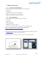
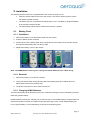
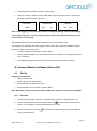
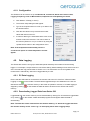
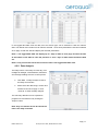
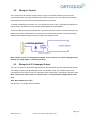
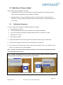
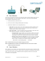
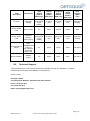
Table of Contents 1. Monitor Components .................................................................................................................... 4 1.1. Series 200 and 300 Monitors .................................................................................................. 4 1.2. Series 500 Monitor .................................................................................................................. 4 2. Installation ..................................................................................................................................... 5 2.1. Battery Pack ............................................................................................................................ 5 2.1.1. Installation ....................................................................................................................... 5 2.1.2. Removal .......................................................................................................................... 5 2.1.3. Charging Ni-MH Batteries ............................................................................................... 5 2.1.4. Charging Lithium Polymer Batteries................................................................................ 6 2.1.5. Safety Information ........................................................................................................... 6 2.2. Sensor Heads.......................................................................................................................... 7 2.2.1. Sensor Warm Up ............................................................................................................. 7 2.2.2. Sensor Head Failure ....................................................................................................... 7 2.3. Optional Temperature and Relative Humidity Sensor ............................................................ 8 3. Operation ....................................................................................................................................... 8 3.1. Series 200 Display .................................................................................................................. 8 3.2. Series 300 & 500 Display ........................................................................................................ 8 3.3. Powering On and Off ............................................................................................................... 9 3.4. Menu Functions ....................................................................................................................... 9 3.4.1. Units .............................................................................................................................. 10 3.4.2. Max/Min/Average Measurement Cycle ......................................................................... 10 3.4.3. Calibration ..................................................................................................................... 11 3.4.4. Mute Key ....................................................................................................................... 11 3.4.5. Location ID (Series 300 & 500) ..................................................................................... 11 3.4.6. Monitor ID (Series 300 & 500) ....................................................................................... 11 3.4.7. Output Sensor (Series 300 & 500) ................................................................................ 12 3.4.8. Alarm Points (Series 300 & 500) ................................................................................... 12 3.4.9. Control Points (Series 300 & 500)................................................................................. 13 3.4.10. Clock Setup (Series 500) .............................................................................................. 13 3.4.11. Logging Setup (Series 500) .......................................................................................... 13 4. Aeroqual Monitor Software (Series 500) ................................................................................... 14 4.1. Set Up ................................................................................................................................... 14 4.1.1. Connect ......................................................................................................................... 14 4.1.2. Configuration ................................................................................................................. 15 4.2. Data Logging ......................................................................................................................... 15 4.2.1. PC Data Logging ........................................................................................................... 15 4.2.2. Downloading Logged Data from Series 500 ................................................................. 15 4.2.3. Graphs ........................................................................................................................... 16 4.2.4. Tables ............................................................................................................................ 16 4.2.5. Data Analysis ................................................................................................................ 17 4.3. Database Management ......................................................................................................... 18 4.3.1. Exporting data ............................................................................................................... 18 4.3.2. Deleting data ................................................................................................................. 18 4.3.3. Zipping Data .................................................................................................................. 18 Page | 2 MRK-D-0022 V3.1 Aeroqual Series 200, 300 & 500 User Guide 5. External Control Wiring (Series 300 & 500) .............................................................................. 19 5.1. Wiring for Alarm..................................................................................................................... 19 5.2. Wiring for Control .................................................................................................................. 20 5.3. Wiring the 0-5 V Analogue Output ........................................................................................ 20 6. Calibration of Sensor Heads ...................................................................................................... 21 6.1. Calibration Procedure ........................................................................................................... 21 6.2. Zero Calibration ..................................................................................................................... 22 6.3. Span Calibration .................................................................................................................... 22 6.3.1. Procedure ...................................................................................................................... 24 6.4. Bump Test ............................................................................................................................. 24 6.5. Health and safety during calibration ...................................................................................... 24 6.5.1. High pressure leak or failure of pressure regulator ....................................................... 25 6.5.2. Flammability of combustible gases ............................................................................... 25 6.5.3. Toxicity .......................................................................................................................... 25 7. Specifications .............................................................................................................................. 27 7.1. Diagrams ............................................................................................................................... 28 7.2. Optional Extra: Handheld Enclosure ..................................................................................... 29 7.2.1. Specifications ................................................................................................................ 29 7.2.2. Replacing the Sensor Head .......................................................................................... 30 7.2.3. Removing the Monitor ................................................................................................... 30 8. Troubleshooting .......................................................................................................................... 31 8.1. Sensor Failure ....................................................................................................................... 32 8.2. Technical Support ................................................................................................................. 33 9. Guidelines on How to Measure Ozone ..................................................................................... 34 10. Care and Maintenance ................................................................................................................ 35 10.1. Disposal / Recycling .......................................................................................................... 35 11. Appendix ...................................................................................................................................... 36 11.1. Copyright ........................................................................................................................... 36 11.2. Software License ............................................................................................................... 36 11.3. Terms and Conditions ....................................................................................................... 36 11.4. Statements of Compliance ................................................................................................ 37 Page | 3 MRK-D-0022 V3.1 Aeroqual Series 200, 300 & 500 User Guide 1. Monitor Components 1.1. Series 200 and 300 Monitors The following components are supplied with the Series 200 and 300 Monitor: Monitor base Sensor head 12 VDC AC/DC adaptor or Lithium Smart Charger Battery pack – 9.6V Ni-MH or 11.1V Lithium Polymer Optional – Temperature and relative humidity sensor 1.2. Series 500 Monitor The following components are supplied with the Series 500 Monitor: Monitor base Sensor head USB to monitor cable Lithium Smart Charger Battery pack – 11.1V Lithium Polymer Optional – Temperature and relative humidity sensor and two-way adapter cable Note 1: The data logging software for the Series 500 can be found at: http://www.aeroqual.com/products/userguides#prod Please check that all these components have been supplied and contact your distributor or Aeroqual at: [email protected] any of the components are missing. Replacement batteries, sensor heads and other accessories can be purchased separately. Page | 4 MRK-D-0022 V3.1 Aeroqual Series 200, 300 & 500 User Guide 2. Installation The following actions need to be completed before the monitor is ready for use: Insert the sensor head into the top of the monitor. The sensor head is keyed to ensure the head is inserted correctly. The battery must be connected and charged prior to use. The battery is shipped installed in the monitor but disconnected. The temperature and RH sensor needs to be inserted – optional 2.1. Battery Pack 2.1.1. Installation 1. Remove the battery cover and battery pack from the monitor 2. Insert the battery power connector 3. Put the tail end of the battery pack into the hinge points at the bottom of the monitor and clip the top end of the battery pack into the top clips 4. Replace the battery cover on the monitor 1 2 3 4 Note: The NiMH batteries have a green casing; the Lithium batteries have a blue casing 2.1.2. Removal 1. Remove the battery cover from the monitor 2. Insert your thumb under the top left hand side of the battery pack and carefully lever the battery pack out from the retaining clips 3. Unclip the connector from the monitor and remove 2.1.3. Charging Ni-MH Batteries The life of the battery will be affected by the way it is handled. Take good care of the battery pack and follow the guideline below. Ni-MH batteries must be fully charged prior to first-time use. A new Ni-MH battery's full performance is achieved only after a number of complete charge and discharge cycles. A fully charged battery will run for approximately 4-6 hours depending on the sensor head being used. Page | 5 MRK-D-0022 V3.1 Aeroqual Series 200, 300 & 500 User Guide With the adaptor plugged in and unit turned on allow 15 hours for the battery to fully charge. During charging the battery symbol on the display flashes slowly The battery can be charged with the sensor head installed or removed from the base. (Remember to switch off the monitor before removing the sensor head) Unplugging the main power will reset the above charging conditions The batteries can be charged and discharged many times but will eventually wear out When the operating time is noticeably shorter than normal, it is time to replace the battery It is not necessary to fully discharge the battery. When not using the monitor as a portable unit, always plug in the mains adaptor to recharge the battery If left unused a fully charged battery will discharge itself over time 2.1.4. Charging Lithium Polymer Batteries A new battery's full performance is achieved only after a number of complete charge and discharge cycles. A fully charged battery will run for approximately 8 hours depending on the sensor head o o being used. Perform charging at temperatures between 0 C to 45 C. With the adaptor plugged in and unit turned off allow 3 hours for the battery to fully charge. Lithium versions show “Lithium Battery” on the initial monitor start up screen. The battery can be charged with the sensor head installed or removed from the base. (Remember to switch off the monitor before removing the sensor head). The Lithium Smart Charger displays a red LED light when charging and a green LED light when the battery is charged when monitor is off. Note: The unit can be charged when switched on but it will charge more slowly. When the unit is operating the red LED will remain on, even if the battery is fully changed. 2.1.5. Safety Information Do not use the battery pack for any other purpose than operating the Aeroqual monitor Do not disassemble or deface the batteries as this may cause burns Do not incinerate or heat as this may cause burns, the batteries may burst or cause the release of toxic materials Do not short circuit as this may cause burns Use only batteries approved by Aeroqual and recharge your battery only with the AC/DC adaptor supplied with the instrument. Never use any charger or battery that is damaged or worn out Batteries must be recycled or disposed of properly. They must not be disposed of in municipal waste Never charge the battery in a hermitically sealed container Page | 6 MRK-D-0022 V3.1 Aeroqual Series 200, 300 & 500 User Guide 2.2. Sensor Heads Outlet Inlet (meshed) Keyed connector to ensure inserted correctly into base Note: Always place the sensor head perpendicular to the air flow to avoid damage to the sensor 2.2.1. Sensor Warm Up Prior to operation the sensor must be warmed up to burn off any contaminants. When the monitor is first switched on it will warm up for 3 minutes. The reading will then flash for the next 7 minutes to indicate that the sensor is still in the warm up phase. It is recommended that the monitor is kept in Stand By mode when not being used to keep the sensor heated and prevent the build-up of contaminants. If the sensor is new (or unused for long periods) it can take up to 24 hours for the message “sensor warming up” (or “sensor failure” in older models) to disappear. Should the message remain after this time, a genuine sensor failure may have occurred. See the trouble-shooting guide. For Ozone Sensor Heads: 24hours is a conservative time for an ozone sensor to burn off contaminants and achieve its stated performance specification. In most instances this will be achieved well within 24hrs. The warm up period can be reduced by subjecting the sensor to elevated ozone levels for a short period. For example, 0.1 ppm of ozone for 5 minutes typically reduces the warm up time to <30 minutes. Note: Do not remove the sensor head while the monitor is switched on. This may damage the unit. If the sensor head is removed under these conditions without AC/DC adapter connected, the unit will automatically shut down. 2.2.2. Sensor Head Failure There are three possible sensor failure modes, which will be indicated by one of the following messages on the display: “Sensor Failure, Replace sensor” - The sensor head should be replaced as this indicates that there has been component failure. “Sensor aging”–This indicates that the sensor has reached the end of its usable life and the sensor head should be replaced as soon as possible. The measurement readings can no longer be relied upon to be within specification. Note: This message will only apply for O3 Low/Ultra Low sensor heads. “S.F.” – When there is more than one sensor connected, S.F. will show for a sensor failure condition. Page | 7 MRK-D-0022 V3.1 Aeroqual Series 200, 300 & 500 User Guide 2.3. Optional Temperature and Relative Humidity Sensor If the temperature and relative humidity sensor has been purchased, it can be inserted into the PS/2 connector at the base of the monitor. Ensure monitor is turned off before connecting the sensor. Two Way Adaptor Cable Temperature & Relative Humidity Sensor USB to Monitor Cable Note: The monitor will still operate with only the temperature and RH sensor connected. 3. Operation The following instructions detail the operation and set up of the monitor: 3.1. Series 200 Display Power button / Scroll button 3.2. Enter Series 300 & 500 Display Power button Enter Scroll up Alarm mute Scroll down Page | 8 MRK-D-0022 V3.1 Aeroqual Series 200, 300 & 500 User Guide 3.3. Powering On and Off To turn the monitor on: Press and hold the power button until the screen activates. The monitor will turn on and the display will show AEROQUAL MONITOR and the Series Version and Firmware Version. If the monitor is configured for use with a Lithium battery, it will also say “Lithium Battery”. After 5 seconds the display will change to indicate the type of sensor head. The monitor will then warm up. Once warm up is complete the main display will appear as seen below: O3 ULOW 0. 080 M 02 L 03 or ppm O3 UL 0.080 TEMP 21.6C RH 35.1% M 02 L 03 ppm A battery indicator will appear at the bottom of the display when the monitor is operating under Ni-MH battery power only. The indicator shows the battery life remaining The M and L (Monitor and Location) will only show on the Series 300 and 500 If a multi sensor is being used the screen will scroll through the parameters showing each reading, only 3 parameters can be shown on the screen at one time To turn the monitor off: Press and hold the power button for 2 seconds until the monitor beeps. The display will now be blank and operation of the monitor will cease. To activate standby mode: With the monitor on, press the power button once. This will stop operation of the monitor; however the sensor will be kept warm. This mode is used to conserve power between operations but keep the sensor ready to measure the gas concentration with only a short warm up phase needed. In this mode the display will show the sensor type and standby symbol. To return the monitor to operational mode press the power button once. Note 2: When using a Carbon Dioxide sensor head in standby mode, the sensor runs at full power and the fan remains on. 3.4. Menu Functions To enter the set up menu press the enter button on the display. The following menu will appear depending on the Series of handheld: Page | 9 MRK-D-0022 V3.1 Aeroqual Series 200, 300 & 500 User Guide Series 200 Series 300 Series 500 EXIT LOCATION ID MAX MIN AV CALIBRATE MONITOR SET UP EXIT ZERO CAL UNITS MIN MAX AV MUTE KEY EXIT LOCATION ID MAX MIN AV CALIBRATE MONITOR SETUP LOGGING SETUP EXIT MONITOR ID UNITS OUTPUT SENSOR ALARM POINTS CONTROL POINTS MUTE KEY CLOCK SETUP EXIT MONITOR ID UNITS OUTPUT SENSOR ALARM POINTS CONTROL POINTS MUTE KEY 3.4.1. Units To enter, scroll down in the set up menu and select “UNITS”. (Found under “MONITOR SETUP” in the Series 300 and 500) 3 Choose between ppm or mg/m via the scroll button and press enter to confirm the unit selection If there is a temperature and humidity sensor attached there is the option to choose from either °C or °F 3.4.2. Max/Min/Average Measurement Cycle To enter, scroll down in the set up menu and select “MAX MIN AV” Select “start” to initiate the measurement cycle and return to the setup menu Scroll to “EXIT” to return to the main display The readings will scroll along the screen Note: Only three parameters will be shown on the screen at one time. In the Series 300 and 500 the “MAX MIN AV” cycle can also be initiated from the main display by holding down the “scroll down” button for 2 seconds until the unit beeps. Hold down the “scroll down” button again for 2 seconds to stop the measurement cycle. When the “MAX MIN AV” cycle is initiated, the display should read as seen below: O3 UL RD MIN MAX AVE O3 UL TEMP RH PPM 0.010 0.005 0.024 0.015 or RD MIN MAX AVE PPM 0.010 0.005 0.024 0.015 C 23 22 25 24 % 50 50 56 54 Page | 10 MRK-D-0022 V3.1 Aeroqual Series 200, 300 & 500 User Guide Note 1: The MIN, MAX and AVE readings are the minimum, maximum and average readings over the period from the start of the cycle. Note 2: The RD value is the current reading. Note 3: The speed of the display scrolling is dictated by the slowest sensor. The display will scroll every time a new set of readings have been taken. 3.4.3. Calibration To enter, scroll down in the set up menu and select either “ZERO CAL” on the Series 200 or “CALIBRATE” on the Series 300 and 500. To enter the calibrate menu the “mute” and “scroll down” button needs to be held down for 2 seconds. From here either “ZERO CAL” or “SPAN CAL” can be selected. For more information on how to calibrate the sensor heads please refer to Section 6 of the User Guide. 3.4.4. Mute Key To mute the audible feedback “beeps” that occur when you press a button, scroll down in the set up menu and select “MUTE KEY”. (Found under “MONITOR SETUP” in the Series 300 and 500) Press the enter key to silence the audible feedback “beeps”, the word muted will appear next to MUTE KEY On the Series 200, if the device is turned off the mute settings will be returned to the default state and will have to be reset when the monitor is restarted 3.4.5. Location ID (Series 300 & 500) To select the location ID, scroll down in the set up menu and select “LOCATION ID” The location ID provides a means of identifying the location where a measurement was taken. This can be used to quickly trace a measurement back to a location Location ID is logged for each measurement Press “enter” to confirm the ID and return to the set up menu 3.4.6. Monitor ID (Series 300 & 500) The monitor ID can be found under “MONITOR SETUP”, scroll down in the monitor set up menu and select “MONITOR ID” Each monitor can be numbered to identify them quickly when more than one is in use Data is tagged with the monitor ID at the time it is downloaded to the PC, so you can use more than one monitor with a single instance of PC software (S500 only). Each record in the database contains date/time, monitor id, location id, sensor type, sensor reading. Page | 11 MRK-D-0022 V3.1 Aeroqual Series 200, 300 & 500 User Guide For compatibility purposes the database records for earlier versions of the S500 (v5.x) default to monitor ID = 1 and location ID = 1. This cannot be changed. Press “enter” to confirm the ID and return to the set up menu. Note: In the Series 500 data logging mode only the Location ID will be logged. The monitor ID is loaded to the database at the time of data upload (where it is logged). 3.4.7. Output Sensor (Series 300 & 500) If a multi-sensor head is connected, the output sensor selection will determine which sensor the alarm and control points and buzzer refer to The output sensor can be found under “MONITOR SETUP”, scroll down in the monitor set up menu and select “OUTPUT SENSOR” and select the relevant parameter The 0-5v analogue signal will also operate on the selected sensor and measurement range 3.4.8. Alarm Points (Series 300 & 500) The alarm points can be found under “MONITOR SETUP”, scroll down in the monitor set up menu and select “ALARM POINTS” Once the alarm set up menu has been entered “ALARM HI” will display Press the “scroll up” and “scroll down” buttons to select the correct concentration Press “enter” to confirm the change Once the high alarm has been set “ALARM LO” will display Press the “scroll up” and “scroll down” buttons to select the correct concentration Press “enter” to confirm the change Once the low alarm has been set “BUZZER” display will show. Here you can either enable or disable the alarm. If the alarm is disabled a “P” will show on the right hand side of the alarm mute symbol on the main display, highlighting that the alarm has been permanently muted. If the concentration reaches above the high alarm point two flashing arrow symbols pointing upwards will appear on the display, accompanied by a fast beeping sound. If the concentration reaches above the low alarm point two flashing arrow symbols pointing downwards will appear on the display, accompanied by a slow beeping sound. Note: The alarm can be muted by pressing the mute button on the display screen. However, this is only a temporary mute and will only mute the alarm during that specific alarm condition. Once the concentration has moved back into the alarm limits the settings will reset. To turn of the mute permanently follow instructions to disable the alarm. Page | 12 MRK-D-0022 V3.1 Aeroqual Series 200, 300 & 500 User Guide 3.4.9. Control Points (Series 300 & 500) The control points can be found under “MONITOR SETUP”, scroll down in the monitor set up menu and select “CONTROL POINTS” Once the control points set up menu has been entered “CONTROL HI” will display Press the “scroll up” and “scroll down” buttons to select the correct concentration Press “enter” to confirm the change Once the high point has been set “CONTROL LO” will display Press the “scroll up” and “scroll down” buttons to select the correct concentration Press “enter” to confirm the change 3.4.10. Clock Setup (Series 500) The clock setup can be found under “MONITOR SETUP”, scroll down in the monitor set up menu and select “CLOCK SETUP” To change the hours press the “scroll up” and “scroll down” buttons until correct time is recorded Press “enter” to confirm and adjust the minutes using the “scroll up” and “scroll down” buttons. Repeat to adjust the seconds, month, day and year. Note: The clock is a 24 hour clock 14:30:12 Oct 07 12 3.4.11. Hours: Minutes: Seconds Month: Day: Year Logging Setup (Series 500) To enter, scroll down in the set up menu and select “LOGGING SETUP” The log frequency will appear on the display. Adjust the frequency by using the “scroll up” and “scroll down” buttons Note 1: The frequency is set to 1 minute intervals Once the frequency is set, press the “enter” button to confirm. The option to clear the log will then display on the screen. Press the “scroll up” button to select either YES or NO and press “enter” to confirm the selection. Note 2: The data log can also be cleared directly from the main display screen by holding down the mute button for 2 seconds until the monitor beeps (if the monitor keys are not muted). Page | 13 MRK-D-0022 V3.1 Aeroqual Series 200, 300 & 500 User Guide The display will then give the option to start logging Press the “scroll up” button to select either ON or OFF and press “enter” to confirm the selection and return to the main menu. LOG FREQ. CLEAR LOG 1 MIN YES LOGGING NO ON OFF Note 3: Data logging can also be both started and stopped directly from the main display screen by pressing the “scroll up” button for two seconds until the monitor beeps (if the monitor keys are not muted). When data logging is initiated a triangle will appear on the main display screen. The triangle is an indication that data logging is active, and is also used as an indication of the presence of data, as described below: An empty triangle indicates that no data is stored A filling triangle indicates that some data is stored in the memory. The triangle will fill up in 10% increments. A full triangle indicates that the memory is full and needs downloading to the PC. 4. Aeroqual Monitor Software (Series 500) 4.1. Set Up Computer Requirements USB to monitor cable Window OS version 2000 or later Recommended 512 Mb RAM or more Recommended 1 GHz processor speed or faster Note: S500 V6.0 software will support back to S500 V5.x, earlier versions are incompatible 4.1.1. Connect 1. Connect the Series 500 monitor to a computer using the cable supplied and turn on 2. Launch the Aeroqual Monitor PC software and click on the toolbar to search for the monitor. The unit will be detected automatically and connect 3. Test the connection by clicking on the tool bar. This will display the Monitor Name, Version and ID Number Page | 14 MRK-D-0022 V3.1 Aeroqual Series 200, 300 & 500 User Guide 4.1.2. Configuration The Software can be used to set up the Monitor ID, Location Id, Alarm and Control Limits, Logging Frequency, Units of Measurement, Output Sensor and Updating the Clock. Click Monitor Setup (or Ctrl P) The monitor setup dialog box will appear Type in the required values or scroll up or down to set the desired values. Click the save button to synchronise the monitor values with those on the PC. In order to data log it is essential that the clock on the monitor is set to the real time. This can be done on the monitor (Section 4.4.6.) or via the PC by using the “Update Clock” button in the configuration menu. Note: If the temperature and humidity sensor is connected an option to select temperature unit will appear 4.2. Data Logging The Series 500 monitor can log up to 8188 data points divided by the number of sensors being logged. For example, if a triple sensor is connected it will log 8188/3 readings. Each sensor uses one of the records each log period. Refer to Section 3.4.11 for instructions on how to log data on the monitor itself. Alternatively, data can be logged directly to a PC. 4.2.1. PC Data Logging Ensure that the USB cable is connected to the monitor and to the PC. Click File Start PC Data Logging or click on the toolbar. The data will be logged directly to the database on the PC. No data will be stored on the monitor memory in this mode of operation. However, if PC data logging is stopped by clicking on the toolbar the data will start to be stored in the Series 500 monitor memory. 4.2.2. Downloading Logged Data from Series 500 Logged data from the monitor memory can be downloaded by clicking File Download Logged Data or by clicking on the toolbar. A data download progress bar will appear while the data is downloading. Note: The data will not be removed from the monitor memory. To delete the logged data from the monitor memory select “Clear Log” on the display menu under Logging Setup. Page | 15 MRK-D-0022 V3.1 Aeroqual Series 200, 300 & 500 User Guide If for any reason, the data download does not complete, is terminated or stops: Turn off the monitor to prevent any data loss. Delete the data that has been downloaded to the PC Close the PC software program and repeat the downloading process with the monitor on, connected and with the PC software running. 4.2.3. Graphs While logging directly to a PC, the Real Time View Graph or the Logged Data Graph can be accessed via the “Data” menu on the menu bar. Note: If a multi sensor is plugged in each parameter will been shown in individual tabs 1. The graphs can be configured by clicking Data Graph Default Style or by right clicking on the graph and selecting “Graph Style” 2. To zoom in click on the graph and drag to create a yellow rectangle. The yellow rectangle shows the selected area the graph will zoom into. 3. Right click on the graphs to save or print the graphs Graphs will be saved as a JPG file 4. To reset the graph to the default, right click and select “Reset to Default” 5. The logged data graph can be viewed be clicking Data Graph Logged Data Note 1: In the Logged Data Graph the date, time and sensor type to be viewed can be selected. The Monitor and Location ID can also be selected. Note 2: The Monitor ID is not logged on each record in the monitor but will be stored in the database against each measurement when the data is downloaded. The data will be tagged with whatever the monitor ID is at the time of download. Conversely, the location ID is logged on each record in the monitor. 4.2.4. Tables While logging directly to a PC, the Real Time Table View or Logged Data Table can be accessed via the “Data” menu on the menu bar. Page | 16 MRK-D-0022 V3.1 Aeroqual Series 200, 300 & 500 User Guide In the logged data table view the date, time and sensor type can be selected to view the relevant data. The Monitor and Location ID can also be selected. Once these parameters have been selected click “apply” to filter the data and display the selected parameters. Note 1: The logged data table will display up to 7 days of data on each page. Click the arrows at the bottom of the table to view the previous or next 7 days of data within the filtered data set. Note 2: Only one monitor ID can be viewed at a time in the logged data table view. 4.2.5. Data Analysis The Daily View is a summary for each day, from midnight to midnight, of the Minimum, Maximum and Average readings over the 24 hour period. Click Data Daily Analysis to launch the Daily View window Either select the date range, monitor and location ID and click “Apply” or click “View All” to show the daily analysis. The summary data files can be exported to programs such as MS Excel by clicking the “Export” button. Note: Only one monitor ID can be viewed at a time in the daily view table. Page | 17 MRK-D-0022 V3.1 Aeroqual Series 200, 300 & 500 User Guide 4.3. Database Management 4.3.1. Exporting data To export the database click File Export Logged Data The table above will appear. The database can be filtered using the date, time, monitor ID, location ID and sensor type parameters to select the exact set of data to be exported. Click export, select a directory, choose a file format (either plain text or MS Excel file) and enter a file name. Click “Save” to export the data to the chosen location. Note 1: Only one monitor ID can be exported at a time. Note 2: Up to 50,000 lines of file can be exported at once. If more than 50,000 lines need to be exported it will need to be carried out in two exports. 4.3.2. Deleting data To delete data in the database click File Database Management Delete Data The table above will appear. The database can be filtered using the date, time, monitor ID, location ID and sensor type parameters to select the exact set of data to be deleted. Once the correct data has been selected click delete. A warning notice will appear confirming the data set to be deleted. Click yes to delete the data. Note: Only one monitor ID can be deleted at a time. 4.3.3. Zipping Data 1. To archive logged data, click File Database management Zip Database Select a directory and input a file name to back up all the current stored data to a zipped file. Page | 18 MRK-D-0022 V3.1 Aeroqual Series 200, 300 & 500 User Guide 2. To view archived logged data, Click File Database management Unzip Database Select the zipped file and click OK. View and analyse data as required (Data Table Logged) Note: To view an archived database it is important that any existing data logging function is not interrupted. Do not view archived data on the same PC being used for data logging; the current data in the database will be lost unless it has been zipped. 5. External Control Wiring (Series 300 & 500) The pin numbers for the external output connector are numbered from 1 to 6. Pin 1 is the closest pin to the power jack. The pin designations are as follows: 1. 12 V DC 2. Analogue output 0-5 V 3. Control 4. High alarm 5. Low alarm 6. Ground The RJ12 connector offers two possibilities for wiring, either a switch to GND or a 12V output. If the 12V output is used, the power for the relay coil is supplied by the Aeroqual AC/DC adaptor. In this case, ensure that the relay coil does not draw more than 150mA and that a protection diode is inserted across the relay coil. If the switch to GND output is used, ensure that the relay coil does not draw more than 150mA, that the voltage does not exceed 24V and that a protection diode is inserted across the relay coil. 5.1. Wiring for Alarm The high alarm and low alarm pins can be wired to supply simple on / off switching to operate equipment which requires only an on or off signal, such as an alarm. To switch to GND use pins 4, 5 and 6. For a 12V output wire to pins 4, 5 and 1 (see the following diagram for typical wiring for high alarm). This feature will only operate while powered by the AC adaptor. High gas level alarm Note: Failure to insert a circuit protection diode, shown as above, will result in damage to the monitor if a voltage spike is created by the relay. Page | 19 MRK-D-0022 V3.1 Aeroqual Series 200, 300 & 500 User Guide 5.2. Wiring for Control The control pin can be wired to supply control of a gas concentration between upper and lower concentration limits. The upper and lower limits can be set by the user. The factory default settings are dependent on the gas sensor head selected at time of purchase. To switch to GND use pins 3 and 6. For a 12V output wire to pins 3 and 1 (see following diagram for typical wiring). This feature will only operate while powered by the AC adaptor. Control is achieved by using a software latch. If power is lost to the monitor, the switch will open and therefore turn off the external device connected to the monitor external output. The following wiring diagram demonstrates the typical wiring to achieve the required control. Note: Failure to insert a circuit protection diode, shown as above, will result in damage to the monitor if a voltage spike is created by the relay. 5.3. Wiring the 0-5 V Analogue Output The 0 to 5 V signal is a proportional signal based on the measurement of the selected output sensor. The voltage out spans the specified gas sensor concentration range. For example: With the low concentration ozone sensor head: 0 V represents 0 ppm ozone and 5 V represents 0.500 ppm ozone. Note: The ultra-low ozone sensor is a special case – 1.5V represents 0.150ppm ozone in this case. Note: Wire between pins 2 & 6 See Section 7.1 for output status conditions. Page | 20 MRK-D-0022 V3.1 Aeroqual Series 200, 300 & 500 User Guide 6. Calibration of Sensor Heads Sensor heads can be calibrated in two ways: 1. Via replacement. Return your sensor head to Aeroqual and purchase a replacement sensor with a multi-point calibration and new calibration certificate. 2. Manual calibration. The easy calibration procedure is outlined below. Aeroqual supplies a Calibration Accessory (R42) to facilitate humidity control and delivery of calibration gas to the sensor head. 6.1. Calibration Procedure In order to calibrate successfully the following equipment is needed: R42 Calibration Accessory Inert tubing (Regulator to gas inlet) See table for gas/material compatibility 0.5 LPM constant flow regulator (eg Calgaz regulator model 715, flow rate 0.5 LPM) Span gas in air cylinder Zero grade air cylinder 1. Charge R42 Calibration Gas Accessory with 5g of water with water syringe via water inlet. 2. Fit cylinder and regulator to R42 gas inlet via tubing and Luer attachment. 3. Place warmed up Aeroqual sensor head in R42 outlet as shown below. The Aeroqual sensor head is now ready for zero or span calibration. Note: The inlet of the sensor head should be inserted into the outlet of the R42 (the inlet of the sensor head has a mesh cover) Note: The MS1 and MS2 multi-sensor heads require that the sensor head be inserted in different positions depending on the sensors being calibrated. Use this orientation for calibrating PID and CO2 Use this orientation for calibrating CO Page | 21 MRK-D-0022 V3.1 Aeroqual Series 200, 300 & 500 User Guide 2 1 6.2. 3 Zero Calibration Under some circumstances the sensors may temporarily exhibit a baseline reading higher than zero due to insufficient warm up or cross-sensitivity to other gases. In this case it is also worthwhile checking against a standard zero air source. 1. Follow the initial set up instructions in 6.1 2. Flow zero air until the reading stabilises (about 10 minutes) 3. Initiate Zero Calibration on the Aeroqual Monitor by: Series 200: Press and hold the “enter” button until the word “Zeroing” appears next to ZERO CAL. The routine will run for up to ten minutes (depending on the gas sensor installed) and then beep to indicate completion. Series 300 and 500: : Enter the CALIBRATE menu by pressing the “mute” and “scroll down” buttons for 2 seconds. From here select “ZERO CAL” then: o Single gas heads: Toggle YES/NO using scroll button to YES then press enter. The word “Zeroing” appears and the zero routine will run for up to ten minutes (depending on the gas sensor installed) and then beep to indicate completion. o Multi-gas sensor heads and T/RH probe: Press enter to bring up the OFFSET for the Sensor head. Use the scroll buttons to change the OFFSET and enter button to accept. Calculate the new OFFSET using the equation below: New OFFSET = Sensor Reading/GAIN + old OFFSET Note 1: The Series 200 can only zero calibrate single gas sensors. Note 2: Temp/RH offsets are stored on the handheld rather than on the sensor. All other offsets are stored on the sensors. 6.3. Span Calibration Span calibration is only available on the Series 300 and 500. It provides an option to adjust the GAIN of Aeroqual sensor heads. There are no optimum span concentrations for calibrating Aeroqual sensor heads. There are however a few considerations which can guide the decision as to which span concentration is most appropriate. Page | 22 MRK-D-0022 V3.1 Aeroqual Series 200, 300 & 500 User Guide For the majority of uses, gases will be purchased for calibration at the concentration to be used for the span calibration, rather than purchased at high concentrations and later diluted using a gas dilution calibrator. Therefore users may find some restrictions on what concentrations can be provided by their chosen calibration gas supplier. For some applications measurements will be made close to the monitor’s maximum detection limit. For these applications a span point at 80 % of full scale is suggested. For other applications, gas levels may be important across a broad range rather than just close to the maximum exposure limit. Other applications may make more use of the lower end of the sensors working range, with higher levels occurring less frequently and having less importance. The most appropriate span point will thus depend upon the intended application. If the intended application is not known, Aeroqual suggests a span point at 80 % of full scale. All gases should be purchased in a balance of air. Suggested span point 80 % Full Scale (in a balance of air) Tubing material for gas calibration Carbon Monoxide 0-25 ppm 20 Tygon R-3606 Carbon Monoxide 0-100 ppm 80 Tygon R-3606 Carbon Monoxide 0-1000 ppm (leak) 800 Tygon R-3606 Carbon Dioxide 0-2000 ppm 1600 Tygon R-3606 Carbon Dioxide 0-5000 ppm 4000 Tygon R-3606 0.8 PTFE (Teflon) Aeroqual Sensor Head Nitrogen Dioxide 0-1 ppm NH3 0-100ppm * NH3 0-1000ppm (leak) * Hydrogen 0-5000 ppm 4000 H2S 0-10 ppm 8 PTFE (Teflon) H2S 0-100 ppm 80 PTFE (Teflon) Methane 0-10000 ppm 8000 PTFE (Teflon) Ozone (OZU) 0-0.15 ppm 0.12 PTFE (Teflon) Ozone (OZL) 0-0.5 ppm 0.4 PTFE (Teflon) 8 PTFE (Teflon) SO2 0-10 ppm 8 PTFE (Teflon) SO2 0-100 ppm 80 PTFE (Teflon) Ozone (OZG) 0-10 ppm PERC 0-200 ppm * VOC (Isobutylene) 0-25 ppm 20 PTFE (Teflon) VOC (Isobutylene) 0-500 ppm 400 PTFE (Teflon) 20 16 800 PTFE (Teflon) PTFE (Teflon) PTFE (Teflon) NMHC (Isobutylene) 0-25 ppm PID (Isobutylene) 0-20 PID (Isobutylene) 0-1000 * The R42 cannot be used for the calibration of NH3 due a material incompatibility. Contact Aeroqual for advice on calibrating NH3 sensor heads. ** Contact Aeroqual for information regarding PERC calibration Page | 23 MRK-D-0022 V3.1 Aeroqual Series 200, 300 & 500 User Guide 6.3.1. Procedure 1. Follow the initial set up instructions in section 6.1 2. Flow the target gas at 0.5 LPM 3. Measure the gas concentration on the monitor screen and wait for it to stabilise (10 minutes). 4. If the Aeroqual sensor head requires a span adjustment then enter the CALIBRATE menu by pressing the “mute” and “scroll down” buttons simultaneously for 2 seconds. Then select SPAN CAL and change the GAIN using the scroll buttons. Calculate the new GAIN using the equation below: New GAIN = Old GAIN x Span Gas Concentration (ppm) / Sensor Reading Note 1: Temp/RH GAINs are stored on the handheld rather than on sensor. All other GAINs are stored on the sensors. 6.4. Bump Test Operators may wish to have increased confidence in the operation of their monitor by performing a bump test prior to taking measurements. A bump test involves quickly exposing the sensor to span gas and confirming the sensor indicates an elevated response. The equipment for performing a bump test is the same as for performing a span calibration, however it is not necessary to wait for the monitor to warm up before performing a bump test, nor is it necessary to wait for the monitor readings to stabilize to confirm a successful bump test. Turn on the monitor and place it at the outlet of the R42, you will need to wait three minutes before readings will be displayed on the monitor. Turn on the span gas and observe the sensor reading, the reading should quickly elevate above the baseline reading and approach that of the span gas concentration. If the reading does not approach that of the span concentration this could indicate a monitor fault or the need to perform a calibration. Once an elevated reading has been observed close to the span gas concentration the gas can turned off, you must then wait for the readings to come down to baseline level before taking measurements. 6.5. Health and safety during calibration Upmost care must be taken while performing a zero or span calibration. Cylinder gas can cause harm in a number of ways. There a number of sources of good information about the correct use and storage of compressed gases. The following resources may prove useful: The National Institute for Occupational Safety and Health: http://www.cdc.gov/NIOSH/ Page | 24 MRK-D-0022 V3.1 Aeroqual Series 200, 300 & 500 User Guide The United States Department of Labour http://www.osha.gov/SLTC/compressedgasequipment/index.html The following information is a guide for what to consider when handling compressed gas but Aeroqual recommends operators adhere to their local regulations regarding compressed gas handling. 6.5.1. High pressure leak or failure of pressure regulator Many calibration gases are held in cylinders at high pressure in excess of 1000 Psi. Incorrectly fitting the pressure regulator, using a regulator which is faulty or knocking the cylinder over while the regulator is attached can cause physical harm from high speed projectiles resulting from a high pressure leak from or failure of the regulator. It is important to always fit a high quality undamaged pressure regulator to the gas cylinder and that the regulator type is suitable for the cylinder you are attaching it to. Always use protective eyewear (safety glasses) when working with compressed gas. Always point the cylinder and regulator away from yourself and others when attaching or removing the pressure regulator. Always secure the cylinder to prevent it from being knocked over while the regulator is attached. 6.5.2. Flammability of combustible gases Calibration gas can be stored in cylinders at high concentrations and can this can present a hazard if those gases are combustible. The lower explosive limit (LEL) is the lowest concentration of gas at which combustion will be sustained in air if an ignition source (spark or flame) is present. The LELs for the gases used for calibrating Aeroqual sensor heads are all significantly above the calibration span points so this risk is low. It is important however that the LEL be known for the gas being employed and that suitable precautions be taken to further minimize the risk from explosive combustion such as performing the calibration in a fume hood. The table below lists the LELs for the gases used to calibrate Aeroqual’s sensor heads. 6.5.3. Toxicity While most of the recommend span points fall below the Immediately Dangerous to Life or Health (IDLH) limits published by the National Institute for Occupational Health and Safety (NIOSH), some span points are above these limits and therefore it is crucial that rigorous health and safety procedures be followed during calibration to avoid exposure to the calibration gas. The table below lists the IDLH concentration limits as well as concentration limits for longer exposure times. The LDLH limits are known for most of the gases of concern, however there are some gases for which data are not available. In these cases gases should be considered as being toxic and Page | 25 MRK-D-0022 V3.1 Aeroqual Series 200, 300 & 500 User Guide handled as such. Health and safety data are often revised, Aeroqual recommends checking external sources for the most up to date information. Aeroqual suggests that all span calibrations be performed in a fume hood such as the one in the image below to avoid exposure to personal. Gas IDLH (ppm) PEL (ppm) STEL (ppm) LEL (ppm) Carbon Monoxide 1200 25 N/A 125,000 Carbon Dioxide 40000 5000 30000 N/A Nitrogen Dioxide 20 N/A 1 N/A Ammonia (NH3) 300 25 35 150,000 Hydrogen N/A N/A N/A 40,000 Hydrogen Sulfide 100 10 15 40,000 Methane N/A N/A N/A 50,000 Ozone 5 0.1 0.3 N/A PERC N/A N/A N/A N/A Sulphur Dioxide 100 2 5 N/A Isobutylene N/A N/A N/A 18,000 IDLH: Immediately Dangerous to Life or Health PEL: Permissible exposure limit (usually based upon a time weighted 8 hour average STEL: Short - term exposure limit ( 1 hour average) LEL: Lower explosion limit Source: http://www.cdc.gov/niosh/idlh/intridl4.html 21/06/2013 (always check for latest information) Page | 26 MRK-D-0022 V3.1 Aeroqual Series 200, 300 & 500 User Guide 7. Specifications The Aeroqual handheld monitors have been specifically designed to incorporate Aeroqual’s in-depth knowledge of accurate ambient gas measurement and can be used with a wide range of gas sensor heads. The sensor heads are interchangeable and therefore multiple heads can be used on the same base unit. The sensors are calibrated prior to delivery. Gas measurement units ppm or mg/m3 Reading functions Minimum, maximum, average Sensor head Interchangeable, replaceable Display type Rechargeable battery LCD Battery, sensor, standby, mute, high/low alarm, monitor ID, location ID. Zero and span via secret menu 12V DC (power adaptor/charger supplied 100250V AC) Ni-MH 9.6V DC | 2100mA/h or Lithium 11.1V Temperature & Humidity sensor Temp: -40°C to 124°C; RH: 0 to 100% Size (with sensor head) 195 x 122 x 54 (mm) Weight (with sensor head and battery) < 460 g o o Temperature: -5 C to 45 C Humidity: 0 to 95% non-condensing PC and ABS; IP20 and NEMA 1 equivalent Display status indicators Sensor calibration features (S300 S500) Power supply Environmental operating conditions Enclosure material and rating Audible Alarm (S300 & S500) External transistor outputs for alarms & control (S300 & S500)* Analogue output (S300 & S500) Low alarm, high alarm Digital interface (S500) RS232 with USB converter Data logging capacity (S500) 8188 data points in total PC data logging (S500) Software and data cable supplied Clock function (S500) Real time Part 15 of FCC Rules EN 50082-1: 1997 EN 50081-1: 1992 Approvals 12 VDC or switch to GND (150 mA max) 0-5V *All of the transistor outputs are open collector current sink. The maximum rating of these transistor outputs is 12VDC at 150mA. Should you connect a relay or any other inductive load to the transistor outputs, a back EMF suppression diode must be fitted across the load. Aeroqual accepts no responsibility for damage to this product or any other issues arising from the non-compliance with the above directives. Failure to implement these directives will invalidate the warranty on this product. Page | 27 MRK-D-0022 V3.1 Aeroqual Series 200, 300 & 500 User Guide 7.1. Diagrams Page | 28 MRK-D-0022 V3.1 Aeroqual Series 200, 300 & 500 User Guide 7.2. Optional Extra: Handheld Enclosure The handheld FRP enclosure is designed for fixed or secure monitoring. The inlet nozzles are specifically designed to eliminate dust and reduce water ingress whilst minimising destruction of part per billion gas concentrations or measurement variations due to outgas contamination from the enclosure. The sensor heads are specifically calibrated to take into account the longer flow path. Sensor heads fitted to this product must be the Type 2 sensor heads that are capable of operating with the longer flow path. 7.2.1. Specifications Dimensions Height (including cable gland) 283 mm Width 180 mm Depth 90 mm Fibre-glass reinforced polycarbonate base Materials Polycarbonate lid Mounting Screw fixture Operating temperature -35°C to 120°C Inlet Outlet Temp/RH sensor connection Power Connection Data logging connection Page | 29 MRK-D-0022 V3.1 Aeroqual Series 200, 300 & 500 User Guide 7.2.2. Replacing the Sensor Head 1. Undo the four lid screws at each corner using a flat headed screw driver and remove the lid. 2. Unscrew and remove the inlet and outlet nozzles and threaded lock nuts on either end. 3. Remove the sensor head by carefully pulling it upwards, disconnecting it from the monitor. 4. Replace the sensor head. 5. Re-insert the nozzles and tighten using the lock-nuts on either end and ensure there is a tight fit against the sensor head. 6. Replace the lid and tighten the four lid screws. Lock Nut Lock Nut 7.2.3. Removing the Monitor 1. Undo the four lid screws at each corner using a flat headed screw driver and remove the lid. 2. Loosen the lock nuts on either end of the sensor head. 3. Depress the blue plastic clips on either side of the monitor unit and then lift the monitor up. 4. This will expose the rechargeable battery and also allow the mounting screws holding the blue battery cover to be accessed. 5. Carefully disconnect the monitor from the sensor head and remove from the enclosure. 6. Reverse the process to reconnect the monitor back onto the battery cover. Page | 30 MRK-D-0022 V3.1 Aeroqual Series 200, 300 & 500 User Guide 8. Troubleshooting Fault Description No power Possible cause Lead connection broken Reconnect power lead Power supply failure Replace 12V DC power supply Battery flat Recharge battery Unit damaged Replace unit Sensor head damaged Replace sensor head Insufficient warm up Run the sensor on full power for 24-48 hours. If using an ozone sensor head and an O3 source is available, exposure to 100 ppb for 5 minutes will speed up the decontamination process (approximately 30 minutes) Air contaminated Move the sensor to cleaner environment and check reading Sensor damaged Replace sensor Sensor failure when the sensor is new Background gas level higher than normal Move sensor to clean air and check reading is zero or close to zero Interfering gas present Move sensor to clean air and check reading is zero or close to zero Sensor zero drift ZERO CAL sensor zero grade air using R42 Sensor damaged Replace sensor Sensor correct Check calibration of gas generator. Interfering gas present Move sensor to clean air and check reading upon exposure to known gas concentration Sensor calibration lost Replace /refurbish sensor Sensor correct Check calibration of gas generator Sensor inlet contaminated Clean sensor inlet filter and mesh Sensor fan failed Replace sensor Reading high under zero gas conditions Reading higher than expected in the presence of sensor gas Reading lower than expected reading in the presence of sensor gas Remedy Page | 31 MRK-D-0022 V3.1 Aeroqual Series 200, 300 & 500 User Guide Interfering gas present Move sensor to clean air and check reading upon exposure to known gas concentration Gas reactive and de-composing before detection Move the monitor closer to them source of the gas Local air flow too high (ozone sensors) or too low (VOC and ammonia sensors) Modify the airflow into and around sensor head. Sensor calibration lost Replace /refurbish sensor Power supply unstable Install stable power supply Power supply current rating incorrect Install power supply with correct rating Local air flow too high Reduce air flow Environmental conditions fluctuating Reduce fluctuations EMI noise picked up via USB cable and PC (S500 unit only) Unplug cable to determine if this reduces the instability. If this solves the problem then isolate the power on PC Incorrect RJ12 pins used Check pins and wire correctly No diode across external relay coil Fit diode across external relay coil Diode polarity incorrect Fit diode correctly Connections broken Reconnect leads COM Port settings incorrect Setup COM port correctly Clock setting incorrect Synchronise clock with PC. If this does not work then the Monitor clock battery may be flat. Return monitor to Aeroqual for battery replacement. Reading unstable External alarm and control doesn't work correctly (Series 300 and 500 units only) USB communications unstable (S500 only) 8.1. Sensor Failure The handheld monitors have inbuilt diagnostics to detect sensor faults. If the sensor fails it can be easily replaced by simply removing and installing a new one. The failed sensor can be sent back to Aeroqual for refurbishment or disposal. Monitor status conditions are as follows: Page | 32 MRK-D-0022 V3.1 Aeroqual Series 200, 300 & 500 User Guide Control Output (S300 & S500 only) Low Alarm Output (S300 & S500 only) High Alarm Output (S300 & S500 only) Data Logging (S500 only) Fault Description LCD Screen 0-5V Output (S300 & S500 only) No Fault Valid gas reading Reading proportional to gas reading As set by user As set by user As set by user Valid gad reading Sensor Failed Fault Sensor failure 5V Open Closed Closed 9999 Sensor Aging Fault Valid gas reading + sensor aging Reading proportional to gas reading As set by user As set by user As set by user Valid gad reading Communications Failure SENSOR NOT CONNECTED or N.C. or turn off when use Ni-MH battery only 0V Open Open Open No output Sensor Standby Standby symbol 0V Open Open Open No output 8.2. Technical Support Technical information, service and spare parts are available through your distributor. In addition, worldwide technical support is available from Aeroqual Ltd. Please contact: Aeroqual Limited 109 Valley Road, Mt Eden, Auckland 1024, New Zealand Phone: +64 9 623 3013 Fax: +64 9 623 3012 Email: [email protected] Page | 33 MRK-D-0022 V3.1 Aeroqual Series 200, 300 & 500 User Guide 9. Guidelines on How to Measure Ozone The following information is presented to help users operate their Aeroqual monitor with an ozone sensor installed in the most effective and efficient manner. General Ozone is heavier than air and tends to sink. Thus detection of leaks from ozone generating equipment should be performed at the most appropriate position. Ozone will react and decompose on surfaces such as walls, furniture etc. Smell is not a reliable test for the presence or concentration of ozone as the odour threshold varies widely between people and is affected by local ambient conditions. Permanent Controller Placement The Aeroqual Ozone Controller has been designed to measure the ambient concentration of ozone. The controller must not be placed directly in an ozone stream. For indoor local area monitoring attach the controller to an inert surface with the inlet unobstructed. For leak detection mount the unit near the ozone equipment. Ensure that the controller is protected from excessive water splashing, dust, vibration, excessive heat or cold, high concentrations of ozone and excessive swings in humidity. False Readings The Aeroqual Ozone Controller has been designed to respond selectively to ozone. However, other oxidizing gases such as chlorine and nitrogen dioxide can generate false readings if they are at high concentrations. High concentrations of hydrocarbon gases such as vapours of alcohol, oils and solvents can reduce and mask the concentration of ozone. Page | 34 MRK-D-0022 V3.1 Aeroqual Series 200, 300 & 500 User Guide 10. Care and Maintenance Your Aeroqual Monitor is a product of superior design and quality and should be treated with care. When using your Aeroqual Monitor: Keep it and all its parts and accessories out of the reach of small children. Keep it dry. Avoid water and/or condensation as humidity and liquids may damage sensitive electronics and the Li battery. Do not use or store in dusty, dirty areas. Do not store the monitor in temperatures below 10°C or above 35°C. This unit is designed for use at temperatures between -5°C and +45°C however please consult recommended operating temperature for the sensor head which may be different. Avoid sudden changes in temperature which may cause condensation that can damage the electronics. Do not attempt to open. Non-expert handling of the device may cause damage. Do not drop, knock or shake as this could lead to internal damage. Do not use harsh chemicals, cleaning solvents or strong detergents for cleaning. Wipe with a soft cloth slightly dampened with a mild soap-and-water solution In order to maintain measurement accuracy, Aeroqual recommends that users replace or refurbish their sensor heads on a yearly basis or more often if measurement certainty is critical for your application. Please contact your dealer or Aeroqual. 10.1. Disposal / Recycling Please note that this is an electronic product and disposal should be in line with your local or country legislation. The plastic casing of the product is made from a Polycarbonate / ABS blended material (PC + ABS) and is marked accordingly. Page | 35 MRK-D-0022 V3.1 Aeroqual Series 200, 300 & 500 User Guide 11. Appendix 11.1. Copyright Copyright Aeroqual Limited. All rights reserved. Reproduction, transfer, distribution or storage of part or all of the contents of this document in any form without the prior written permission of Aeroqual Limited is prohibited. “Aeroqual” and “Aeroqual Limited – Making the Invisible Visible” are registered trademarks of Aeroqual Limited. Other product and company names mentioned herein may also be trademarks or trade names. Aeroqual operates a policy of continuous development. Aeroqual re-serves the right to make changes and improvements to any of the products described in this document without prior notice. Under no circumstances shall Aeroqual be responsible for any loss of data or income or any special, incidental, consequential or indirect damages howsoever caused. The contents of this document are provided "as is". Except as required by applicable law, no warranties of any kind, either express or implied, including, but not limited to, the implied warranties of merchantability and fitness for a particular purpose, are made in relation to the accuracy, reliability or contents of this document. Aeroqual reserves the right to revise this document or withdraw it at any time without prior notice. The availability of particular products may vary by region. Please check with the Aeroqual dealer nearest to you. 11.2. Software License The Series 500 monitor comes supplied with Aeroqual data logging software. Aeroqual will retain ownership of all intellectual property in the Software. The buyer acknowledges that they are granted a perpetual, non-exclusive, non-transferable license for the right to use the Software for the buyer’s exclusive use and only in conjunction with Aeroqual Products (Intended use). The buyer will strictly adhere to the Intended Use of the Software and will not translate, adapt, reverse compile or otherwise alter the Software. The buyer undertakes not to disclose, assign, sell, rent, lend, sub license or otherwise transfer the Software. 11.3. Terms and Conditions This product is warranted according to Aeroqual Ltd’s Terms of Trade. For further warranty information, please refer to the standard Product Warranty Policy as published on the Aeroqual website at www.aeroqual.com. Page | 36 MRK-D-0022 V3.1 Aeroqual Series 200, 300 & 500 User Guide 11.4. Statements of Compliance 1. The Aeroqual Series 200, 300 and 500 Monitors and Remote Adaptor Kit comply with EN 50082-1:1997 2. The Aeroqual Series 200, 300 and 500 Monitors and Remote Adaptor Kit comply with EN 50081-1:1992 3. The Aeroqual Series 200, 300 and 500 Monitors and Remote Adaptor Kit comply with Part 15 of the FCC Rules. Operation is subject to the following two conditions: (1) these devices may not cause harmful interference, and (2) these devices must accept any interference received, including interference that may cause undesired operation. NOTE: This equipment has been tested and found to comply with the limits for a Class B digital device, pursuant to Part 15 of the FCC Rules. These limits are designed to provide reasonable protection against harmful interference in a residential installation. This equipment generates, uses and can radiate radio frequency energy and, if not installed and used in accordance with the instructions, may cause harmful interference to radio communications. However, there is no guarantee that interference will not occur in a particular installation. If this equipment does cause harmful interference to radio or television reception, which can be determined by turning the equipment off and on, the user is encouraged to try to correct the interference by one or more of the following measures: Reorient or relocate the receiving antenna. Increase the separation between the equipment and receiver. Connect the equipment into an outlet on a circuit different from that to which the receiver is connected. Consult the dealer or an experienced radio/TV technician for help. Page | 37 MRK-D-0022 V3.1 Aeroqual Series 200, 300 & 500 User Guide