1
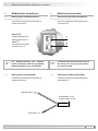
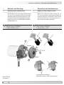
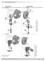
Montage- und Betriebsanleitung Installation and operating instructions GT 7 MB126 gt7_mb (12A1) Tachogenerator Inhaltsverzeichnis Inhaltsverzeichnis 1 Allgemeine Hinweise .................................................................................................................................................... 1 2 Sicherheitshinweise ...................................................................................................................................................... 3 3 Vorbereitung 4 5 6 7 3.1 Lieferumfang 3.2 zur Montage erforderlich bzw. empfohlen (nicht im Lieferumfang enthalten) 3.3 Erforderliches Werkzeug (nicht im Lieferumfang enthalten) Montage ......................................................................................................................................................... 5 ................................................................................................................................................................................. 7 Schritt 1 .................................................................................................................................................................... 7 4.2 Schritt 2 .................................................................................................................................................................... 7 4.3 Schritt 3 .................................................................................................................................................................... 8 4.4 Schritt 4 .................................................................................................................................................................... 8 4.5 Schritt 5 .................................................................................................................................................................... 8 4.6 Schritt 6 .................................................................................................................................................................... 9 4.7 Anbauhinweis Abmessungen .................................................................................................................................................... 10 .................................................................................................................................................................11 5.1 Ausführung GT 7.08 mit Anschlussklemmen 5.2 Ausführung GT 7.08 mit Anschlusskabel 5.3 Ausführung GT 7.16 mit Anschlussklemmen 5.4 Ausführung GT 7.16 mit Anschlusskabel Elektrischer Anschluss Belegung Anschlussklemmen 6.2 Belegung Anschlusskabel Betrieb und Wartung ............................................................................................. 12 ................................................................................................................... 13 ........................................................................................................................... 13 ..................................................................................................................... 14 ....................................................................................................................................................................... 15 8.1 Schritt 1 ................................................................................................................................................................. 15 8.2 Schritt 2 ................................................................................................................................................................. 15 8.3 Schritt 3 ................................................................................................................................................................. 16 8.4 Schritt 4 ................................................................................................................................................................. 16 8.5 Schritt 5 ..................................................................................................................................................................17 8.6 Schritt 6 ..................................................................................................................................................................17 Zubehör 10 Technische Daten 10.1 .............................................................................................................................................................................. 18 ........................................................................................................................................................ 19 Allgemeine Daten 10.2 Daten nach Typ ..................................................................................... 12 ................................................................................................................................................. 14 Austausch der Kohlebürsten Demontage .....................................................................................11 .............................................................................................11 ........................................................................................................................................... 13 6.1 9 11 ..................... 6 ........................................................ 6 4.1 7.1 8 ...................................................................................................................................................................... 5 ............................................................................................................................................ 19 ................................................................................................................................................. 20 Anhang: EU-Konformitätserklärung ............................................................................................................... 23 gt7_mb (12A1) MB126 Table of contents Table of contents 1 General notes 2 Security indications 3 Scope of delivery 4 5 6 7 ...................................................................................................................................................... 4 ............................................................................................................................................................ 5 3.1 Scope of delivery 3.2 required resp. recommended for mounting (not included in scope of delivery) 3.3 required tools (not included in scope of delivery) Mounting ................................................................................................................................................ 5 ................ 6 .............................................................................. 6 ............................................................................................................................................................................... 7 4.1 Step 1 ........................................................................................................................................................................ 7 4.2 Step 2 ........................................................................................................................................................................ 7 4.3 Step 3 ........................................................................................................................................................................ 8 4.4 Step 4 ........................................................................................................................................................................ 8 4.5 Step 5 ........................................................................................................................................................................ 8 4.6 Step 6 ........................................................................................................................................................................ 9 4.7 Mounting instruction Dimensions ....................................................................................................................................... 10 .......................................................................................................................................................................11 5.1 Version GT 7.08 with connecting terminal 5.2 Version GT 7.08 with connecting cable 5.3 Version GT 7.16 with connecting terminal 5.4 Version GT 7.16 with connecting cable Electrical connection ...........................................................................................11 .................................................................................................11 ........................................................................................... 12 ................................................................................................ 12 ................................................................................................................................................. 13 6.1 Connecting terminal assignment 6.2 Connecting cable assignment Operation and maintenance 7.1 8 .................................................................................................................................................................... 2 ............................................................................................................. 13 ................................................................................................................... 13 .................................................................................................................................. 14 Replace of the carbon brushes ................................................................................................................ 14 Dismounting .................................................................................................................................................................... 15 8.1 Step 1 ..................................................................................................................................................................... 15 8.2 Step 2 ..................................................................................................................................................................... 15 8.3 Step 3 ..................................................................................................................................................................... 16 8.4 Step 4 ..................................................................................................................................................................... 16 8.5 Step 5 ..................................................................................................................................................................... 17 8.6 Step 6 ..................................................................................................................................................................... 17 9 Accessories ..................................................................................................................................................................... 18 10 Technical data ................................................................................................................................................................ 21 10.1 General data 10.2 Type data 11 ....................................................................................................................................................... 21 .............................................................................................................................................................. 22 Appendix: EU Declaration of conformity MB126 gt7_mb (12A1) ..................................................................................................... 24 1 Allgemeine Hinweise 1 Allgemeine Hinweise 1.1Zeichenerklärung: Gefahr Warnung bei möglichen Gefahren i Hinweis zur Beachtung Hinweis zur Gewährleistung eines einwandfreien Betriebes des Produkts Information Empfehlung für die Produkthandhabung 1.2Der Tachogenerator GT 7 ist ein Präzisions-Drehzahlmessgerät, das mit Sorgfalt nur von technisch qualifiziertem Personal gehandhabt werden darf. 1.3 Der LongLife Tachogenerator ist wartungsfrei. Lebensdauer der Kohlebürsten unter normalen Bedingungen ≥109 Umdrehungen. Ein Wechsel der Kohlebürsten ist nur vorsorglich erforderlich. 1.4 Der Lagertemperaturbereich des Gerätes liegt zwischen -15°C bis +70°C, 1.5 Der Betriebstemperaturbereich des Gerätes liegt zwischen -30°C bis +130°C, am Gehäuse gemessen. 1.6 EU-Konformitätserklärung gemäß den europäischen Richtlinien. 1.7 Wir gewähren 2 Jahre Gewährleistung im Rahmen der Bedingungen des Zentralverbandes der Elektroindustrie (ZVEI). 1.8 Der Tachogenerator darf nur wie in dieser Anleitung beschrieben geöffnet werden. Reparaturen oder Wartungsarbeiten, die ein vollständiges Öffnen des Tachogenerators erfordern, sind vom Hersteller durchzuführen. 1.9Bei Rückfragen bzw. Nachlieferungen sind die auf dem Typenschild des Gerätes angegebenen Daten, insbesondere Typ und Seriennummer, unbedingt anzugeben. 1.10 1 Alle Bestandteile des Tachogenerators sind nach länderspezifischen Vorschriften zu entsorgen. gt7_mb (12A1) MB126 General notes 1 General notes 1.1 Symbol guide: 1 Danger Warnings of possible danger i General information for attention Informations to ensure correct product operation Information Recommendation for product handling 1.2The tachogenerator GT 7 is a precision rotary measurement device which must be handled with care by skilled personnel only. 1.3 The LongLife tachogenerator is maintenance-free. Life time of the carbon brushes under normal conditions ≥10 9 revolutions. Replacement of the carbon brushes is only a recommended precaution. 1.4 The storage temperature range of the device is between -15°C and +70°C, 1.5 The operating temperature range of the device is between -30°C and +130°C, measured at the housing. 1.6 EU-Declaration of Conformity meeting to the European Council Directives. 1.7 We offer a 2-year warranty in accordance with the regulations of the ZVEI (Central Association of the German Electrical Industry). 1.8 The tachogenerator may be only opened as described in this instruction. Repair or maintenance work that requires opening the tachogenerator completely must be carried out by the manufacturer. 1.9 In the event of queries or subsequent deliveries, the data on the device type label must be quoted, especially the type designation and the serial number. 1.10 Tachogenrator components are to be disposed of according to the regulations prevailing in the respective country. MB126 gt7_mb (12A1) 2 2Sicherheitshinweise 2 Sicherheitshinweise 2.1 Verletzungsgefahr durch rotierende Wellen Haare und Kleidungsstücke können von rotierenden Wellen erfasst werden. •• Vor allen Arbeiten alle Betriebsspannungen ausschalten und Maschinen stillsetzen. 2.2 Zerstörungsgefahr durch mechanische Überlastung •• Die vorgegebenen Abstände und/oder Winkel unbedingt einhalten. 2.3 Zerstörungsgefahr durch mechanischen Schock Starke Erschütterungen, z. B. Hammerschläge, können zur Zerstörung des Gerätes führen. •• Niemals Gewalt anwenden. Bei sachgemäßer Montage lässt sich alles leichtgängig zusammenfügen. •• Für die Demontage geeignetes Abziehwerkzeug benutzen. 2.4 Zerstörungsgefahr durch Verschmutzung Schmutz kann im Tachogenerator zu dessen Beschädigung führen. •• Während aller Arbeiten am geöffneten Tachogenerator auf absolute Sauberkeit achten. •• Bei der Demontage niemals Öl oder Fett in das Innere des Tachogenerators gelangen lassen. 2.5 Zerstörungsgefahr durch klebende Flüssigkeiten Klebende Flüssigkeiten können die Magnete und Kohlebürsten beschädigen. Die Demontage eines mit der Achse verklebten Tachogenerators kann zu dessen Zerstörung führen. 2.6 Explosionsgefahr Den Tachogenerator nicht in Bereichen mit explosionsgefährdeten bzw. leicht entzündlichen Materialien verwenden. Durch eventuelle Funkenbildung können diese leicht Feuer fangen und/oder explodieren. 3 gt7_mb (12A1) MB126 Securtiy indications 2 Security indications 2.1 Risk of injury due to rotating shafts Hair and clothes may become tangled in rotating shafts. 2 • Before all work switch off all operating voltages and ensure machinery is stationary. 2.2 Risk of destruction due to mechanical overload • It is essential that the specified clearances and/or angles are observed. 2.3 Risk of destruction due to mechanical shock Violent shocks, e. g. due to hammer impacts, can lead to the destruction of the device. • Never use force. Assembly is simple when correct procedure is followed. • Use suitable puller for disassembly. 2.4 Risk of destruction due to contamination Dirt penetrating inside the tachogenerator can damage the tachogenerator. • Absolute cleanliness must be maintained when carrying out any work on the open tachogenerator. • When dismantling, never allow lubricants to penetrate the tachogenerator. 2.5 Risk of destruction due to adhesive fluids Adhesive fluids can damage the magnets and the carbon brushes. Dismounting an tacho, secured to a shaft by adhesive may lead to the destruction of the unit. 2.6 Explosion risk Do not use the tachogenerator in areas with explosive and/or highly inflammable materials. They may explode and/or catch fire by possible spark formation. MB126 gt7_mb (12A1) 4 3Vorbereitung / Preparation 3 Vorbereitung 3 Scope of delivery 3.1 Lieferumfang 3.1 Scope of delivery 3 4 5 1 **) 6 1 7 14 9 8 11 10 2 2 *) 15 12 1 Stator 2 Kohlebürsten (4x) 13 1 Stator 2 Carbon brushes (4x) 3 Armature with hollow shaft 3 Anker mit Hohlwelle 4 Spannelement 4 Clamping element 5 Gewindebuchse mit Schlüsselfläche 22 mm 5 Insert nut with spanner flat 22 mm 6 Abschlussdeckel 6 Cover 7 Verschlussstopfen 7 Plug 8 Torx-Befestigungsschraube M3 8 Fixing screw with torx drive M3 9 Klemmendeckel 9 Terminal box cover 10 Scheibe A 3,2, DIN 125 10 Washer A 3.2, DIN 125 11 Torx-Befestigungsschraube M3x25 11 Fixing screw with torx drive M3x25 12 Kabelverschraubung M16x1,5 für Kabel ø5-9 mm 12 Cable gland M16x1,5 for cable ø5-9 mm 13 13 14 Druckschraube mit Scheibe und Dichtring für Kabel ø5-9 mm Anschlussklemmen, siehe Abschnitt 6.1 14 Pressure screw with washer and sealing ring for cable ø5-9 mm Connecting terminal, see section 6.1 15 Anschlusskabel, siehe Abschnitt 6.2 15 Connecting cable, see section 6.2 *) Ausführung mit Druckschraube **)Ausführung mit Anschlusskabel Stator und Anker müssen die gleiche Seriennummer haben. Bei Einsatz ungleicher Nummern kann ein Reversierfehler von max. 0,2% auftreten. 5 *) Version with pressure screw **)Version with connecting cable Armature and stator must have the same serial number. When using different numbers, a reversing error of max. 0.2% may occur. gt7_mb (12A1) MB126 3 Vorbereitung / Preparation 3.2 zur Montage erforderlich bzw. empfohlen (nicht im Lieferumfang enthalten) 16 17 3.2 required resp. recommended for mounting (not included in scope of delivery) 18 4x 16 Befestigungsschraube M4x10, ISO 4017 16 Fixing screw M4x10, ISO 4017 17 Montagekegel, als Zubehör erhältlich, Bestellnummer 11056827 17 Mounting cone, available as accessory, order number 11056827 18 Anschlusskabel ø5-9 mm (nur bei Version mit Anschlussklemmen) 18 Connecting cable ø5-9 mm (only for version with connecting terminal) 3.3 Erforderliches Werkzeug (nicht im Lieferumfang enthalten) 3.3 7 mm und 22 mm, 16 mm*), 17 mm**) 7 mm and 22 mm, 16 mm*), 17 mm**) TX 10 TX 10 *) Ausführung mit Druckschraube **)Ausführung mit Anschlusskabel 19 Werkzeugset als Zubehör erhältlich, Bestellnummer: 11068265 MB126 required tools (not included in scope of delivery) gt7_mb (12A1) *) Version with pressure screw **)Version with connecting cable 19 Tool kit available as accessory, order number: 11068265 6 4Montage / Mounting 4 Montage 4 Mounting 4.1 Schritt 1 4.1 Step 1 6 * 8 * TX 10 3 * 4 * 5 * 22 mm 4.2 Schritt 2 4.2 Step 2 zul. Anzugsmoment: Max tightening torque: Mt = 2-3 Nm 22 mm *siehe Seite 5 see page 5 7 Ansicht X siehe Abschnitt 5 View X see section 5 3 * 4 * 5 * Motorwelle einfetten! Lubricate motor shaft! Die Antriebswelle sollte einen möglichst kleinen Rundlauffehler aufweisen. Der Anbau an den Antrieb muss mit möglichst geringem Winkelfehler und Parallelversatz erfolgen. The drive shaft should have as less runout as possible. The tachogenerator must be mounted on the drive with the least possible angular error and parallel misalignment. gt7_mb (12A1) MB126 Montage / Mounting 4.3 Schritt 3 4.3 4 Step 3 zul. Anzugsmoment: Max tightening torque: Mt = 3 Nm 7 mm 16 * 17 * 1 * 4.4 Schritt 4 4.4 Step 4 17 * Litzenposition beachten! Mind the position of the stranded wire! 4.5 Schritt 5 4.5 6 * Step 5 8 * TX 10 *siehe Seite 5 oder 6 see page 5 or 6 MB126 gt7_mb (12A1) 8 4Montage / Mounting Schritt 6 4.6 Step 6 11 * * 11 TX 10 Ansicht Y siehe Abschnitt 6.1 View Y see section 6.1 17 mm 12 * 13 * 16 mm 18 * *siehe Seite 5 oder 6 see page 5 or 6 Keine Silikonkabel verwenden. Silikonhaltige Atmosphären können zu erhöhtem Kohlebürstenverschleiß führen. 9 15 * Ausführung mit Anschlusskabel Version with connecting cable Ausführung mit Druckschraube Version with pressure screw TX 10 Ausführung mit Druckschraube Version with pressure screw 4.6 Do not use cable with silicone. Atmospheres containing silicone can increase the wearout of the carbon brushes. gt7_mb (12A1) MB126 Montage / Mounting 4.7 i MB126 Anbauhinweis Wir empfehlen, den Tachogenerator so zu montieren, dass der Kabelanschluss keinem direkten Wassereintritt ausgesetzt ist. gt7_mb (12A1) 4.7 i 4 Mounting instruction We recommend to mount the tachogenerator in such a manner that the cable connection is not directly exposed to water. 10 5Abmessungen / Dimensions 5 Abmessungen 5 Dimensions 5.1 Ausführung GT 7.08 mit Anschlussklemmen 5.1 Version GT 7.08 with connecting terminal (80500, 80529, 80550, 80575) (80500, 80529, 80550, 80575) Ansicht X siehe Abschnitt 4.2 View X see section 4.2 ø14h6 ø15h6 ø16h6 ø14H7 ø15H7 ø16H7 Drehrichtung positiv Positive rotating direction 5.2 Ausführung GT 7.08 mit Anschlusskabel 5.2 Version GT 7.08 with connecting cable (80506, 80531, 80555, 80580) (80506, 80531, 80555, 80580) Ansicht X siehe Abschnitt 4.2 View X see section 4.2 ø14h6 ø15h6 ø16h6 ø14H7 ø15H7 ø16H7 Drehrichtung positiv Positive rotating direction All dimensions in millimeters (unless otherwise stated) 11 gt7_mb (12A1) MB126 Abmessungen / Dimensions 5.3 Ausführung GT 7.16 mit Anschlussklemmen 5.3 Version GT 7.16 with connecting terminal (80631, 80650, 80675) (80631, 80650, 80675) Ansicht X siehe Abschnitt 4.2 View X see section 4.2 5 ø12H7 ø14H7 ø15H7 ø16H7 ø12h6 ø14h6 ø15h6 1) ø16h6 Drehrichtung positiv Positive rotating direction 5.4 Ausführung GT 7.16 mit Anschlusskabel 5.4 Version GT 7.16 with connecting cable (80629, 80654, 80680) (80629, 80654, 80680) Ansicht X siehe Abschnitt 4.2 View X see section 4.2 ø12H7 ø14H7 ø15H7 ø16H7 ø12h6 ø14h6 ø15h6 1) ø16h6 Drehrichtung positiv Positive rotating direction Länge der Motorwelle L = 35 Length of the motor shaft L = 35 1) MB126 gt7_mb (12A1) All dimensions in millimeters (unless otherwise stated) 12 6 Elektrischer Anschluss / Electrical connection 6 Elektrischer Anschluss 6 Electrical connection 6.1 Belegung Anschlussklemmen 6.1 Connecting terminal assignment Polarität bei positiver Drehrichtung, siehe Abschnitt 5. Polarity at positive rotating direction, see section 5. _ Ansicht Y Anschlussklemmen siehe Abschnitt 4.6 View Y Connecting terminal see section 4.6 + Zur Gewährleistung der angegebenen Schutzart sind nur geeignete Kabeldurchmesser zu verwenden. To ensure the specified protection of the device the correct cable diameter must be used. 6.2 Belegung Anschlusskabel 6.2 Connecting cable assignment Polarität bei positiver Drehrichtung, siehe Abschnitt 5. Polarity at positive rotating direction, see section 5. braun/brown = + Kabellänge: 0,6 m Cable length: 0.6 m blau/blue = 13 _ gt7_mb (12A1) MB126 Betrieb und Wartung / Operation and maintenance 7 7 Betrieb und Wartung 7 Operation and maintenance 7.1 Austausch der Kohlebürsten 7.1 Replace of the carbon brushes Bei Erreichen der minimalen Bürstenlänge (L) von 5,5 mm sollten die Bürsten ausgewechselt sowie der Kommutatorraum mit trockener Pressluft ausgeblasen werden, damit weiterhin ein einwandfreier Betrieb gewährleistet ist. When the minimum brush length (L) of 5.5 mm is reached , the brushes should be replaced and the commutator area should be cleaned with dry compressed air in order to ensure perfect operation. 2 * 4 Stück Kohlebürsten, als Zubehör erhältlich, Bestellnummer 11075833: 1 Satz (4 Stück) - H 87 2 * 4 pieces carbon brushes, available as accessory, order number 11075833: 1 set (4 pieces) - H 87 L 2 * TX 10 8 * 6 * *siehe Seite 5 see page 5 MB126 gt7_mb (12A1) Litzenposition beachten! Mind the position of the stranded wire! 14 8Demontage / Dismounting 8 Demontage 8 Dismounting 8.1 Schritt 1 8.1 Step 1 6 * 8 * TX 10 11 * 12 * 17 mm * 11 TX 10 13 * 16 mm 18 * 8.2 Schritt 2 *siehe Seite 5 oder 6 see page 5 or 6 15 8.2 Step 2 Ausführung mit Druckschraube Version with pressure screw 18 * Ausführung mit Druckschraube Version with pressure screw TX 10 gt7_mb (12A1) MB126 Demontage / Dismounting 8.3 Schritt 3 8.3 8 Step 3 16 * 7 mm 8.4 Schritt 4 8.4 Step 4 1 * *siehe Seite 5 oder 6 see page 5 or 6 MB126 gt7_mb (12A1) 16 8Demontage / Dismounting 8.5 Schritt 5 8.5 Step 5 3 * 5 * 22 mm 8.6 Schritt 6 8.6 Step 6 3 * 4 * 5 * *siehe Seite 5 see page 5 17 gt7_mb (12A1) MB126 Zubehör / Accessories 9 9 Zubehör Accessories •• Montagekegel, Bestellnummer: 11056827 17 * • Mounting cone, order number: 11056827 17 * •• Kohlebürsten, Bestellnummer: 11075833: 1 Satz (4 Stück) - H 87 2 * • Carbon brushes, order number: 11075833: 1 set (4 pieces) - H 87 2 * •• Werkzeugset, Bestellnummer: 11068265 19 * • Tool kit, order number: 11068265 19 * *siehe Abschnitt 3 MB126 9 gt7_mb (12A1) *see section 3 18 4Montage / 10 TechnischeMounting Daten 10 Technische Daten 10.1 Allgemeine Daten •• Leistung: GT 7.08: 0,3 W (Drehzahl >5.000 U/min) GT 7.16: 0,6 W (Drehzahl >5.000 U/min) •• Kalibriertoleranz: ±5% •• Linearitätstoleranz: ≤0,15% •• Reversiertoleranz: ≤0,1% •• Überlagerte Welligkeit: (für τRC = 0,3 ms) ≤0,6% Spitze-Spitze ≤0,25% effektiv •• Temperaturkoeffizient: ±0,05%/K (Leerlauf) •• Ankerkreis-Zeitkonstante (τA): ≤4 µs •• Leerlaufspannung: 10...60 mV pro U/min •• Drehmoment: 1,5 Ncm •• Trägheitsmoment Rotor: GT 7.08: GT 7.16: •• zulässiger Ankerversatz: ±0,5 mm axial ±0,1 mm radial •• Widerstandsfähigkeit Vibration: (10-2000 Hz) 100 m/s2 ≈ 10 g EN 60068-2-6: 1996-05 •• Widerstandsfähigkeit Schock: (6 ms) 1.000 m/s2 ≈ 100 g EN 60068-2-27: 1995-03 0,4 kgcm2 0,6 kgcm2 •• Betriebstemperatur:-30°C...+130°C 19 •• Isolationsklasse: B •• Schutzart IEC 60529: IP 55 •• Klimatische Prüfung: IEC 60068-2-3, Ca (Feuchte Wärme, konstant) •• Masse ca.: GT 7.08: GT 7.16: •• EMV gemäß: EN 61000-6-2: 2006-03 (Störfestigkeit) EN 61000-6-4: 2007-09 (Störaussendung) 110 g 160 g gt7_mb (12A1) MB126 Montage / Mounting 10.2 10 4 Daten nach Typ Leerlaufspannung Typ Min. erforderlicher Lastwiderstand in Abhängigkeit vom Drehzahlbereich [U/min] max. Betriebsdrehzahl AnkerWiderstand AnkerInduktivität 0-3.000: 0-6.000: 0-nmax: U0 [mV/ U/min] RL [kΩ] RL [kΩ] RL [kΩ] nmax [U/min] R A (20°C) [Ω] LA [mH] 10 ≥5 ≥12 ≥27 9.000 60 20 GT 7.08 L / 410 GT 7.08 L / 420 20 ≥20 ≥48 ≥108 9.000 230 80 GT 7.08 L / 430 30 ≥45 ≥108 ≥243 9.000 550 180 GT 7.16 L / 440 40 ≥40 ≥96 ≥216 9.000 410 160 GT 7.16 L / 460 60 ≥90 ≥215 ≥223 6.100 760 360 Polarität bei positiver Drehrichtung (siehe Abschnitt 5): 2A1: +2A2: -(VDE) U(n) RA LA U0(n) R 2A1 U(n) RL C -n n 2A2 GT 7 -U(n) τRC ≈ R . C MB126 LA τA ≈ R L gt7_mb (12A1) RL U(n) = U0(n) R A + RL ≈ U0(n) für R > RL >> R A 20 10 Technical data 10 Technical data 10.1 21 General data • Performance: GT 7.08: GT 7.16: • Calibration tolerance: ±5% • Linearity tolerance: ≤0.15% • Reversing tolerance: ≤0.1% • Superimposed ripple: (for τRC = 0.3 ms) ≤0.6% peak-peak ≤0.25% rms • Temperature coefficient: ±0.05%/K (idle) • Armature-circuit time-constant (τA): ≤4 µs • Open-circuit voltage: 10...60 mV per rpm • Torque: 1.5 Ncm • Rotor moment of inertia: GT 7.08: GT 7.16: • Permissible armature displacement: ±0.5 mm axial ±0.1 mm radial • Vibration resistance: (10-2000 Hz) 100 m/s2 ≈ 10 g EN 60068-2-6: 1996-05 • Shock resistance: (6 ms) 1,000 m/s2 ≈ 100 g EN 60068-2-27: 1995-03 • Operating temperature: -30°C...+130°C • Isolation class: B • Protection class IEC 60529: IP 55 • Climatic tests: IEC 60068-2-3, Ca (dump heat, constant) • Weight approx.: GT 7.08: GT 7.16: • EMC according to: EN 61000-6-2: 2006-03 (interference immunity) EN 61000-6-4: 2007-09 (emitted interference) 0.3 W (speed >5,000 rpm) 0.6 W (speed >5,000 rpm) 0.4 kgcm2 0.6 kgcm2 110 g 160 g gt7_mb (12A1) MB126 10 10.2 Type data Off-load voltage Type Minimum load required depending on speed range [rpm] Maximum operating speed Armature resistance Armature inductance 0-3,000: 0-6,000: 0-nmax: U0 [mV/rpm] RL [kΩ] RL [kΩ] RL [kΩ] nmax [rpm] R A (20°C) [Ω] LA [mH] 10 ≥5 ≥12 ≥27 9,000 60 20 GT 7.08 L / 410 GT 7.08 L / 420 20 ≥20 ≥48 ≥108 9,000 230 80 GT 7.08 L / 430 30 ≥45 ≥108 ≥243 9,000 550 180 GT 7.16 L / 440 40 ≥40 ≥96 ≥216 9,000 410 160 GT 7.16 L / 460 60 ≥90 ≥215 ≥223 6,100 760 360 Polarity for positive rotating direction (see section 5): 2A1: +2A2: -(VDE) U(n) RA LA U0(n) U(n) U0(n) ≈ U(n) R 2A1 RL C -n n 2A2 GT 7 -U(n) τRC ≈ R . C MB126 LA τA ≈ R L gt7_mb (12A1) RL U(n) = U0(n) R A + RL ≈ U0(n) for R > RL >> R A 22 11 Anhang: EU-Konformitätserklärung 11 Anhang: EU-Konformitätserklärung 23 gt7_mb (12A1) MB126 Appendix: EU Declaration of conformity 11 MB126 11 Appendix: EU Declaration of conformity gt7_mb (12A1) 24 Originalsprache der Anleitung ist Deutsch. Technische Änderungen vorbehalten. Original language of this instruction is German. Technical modifications reserved. Baumer Hübner GmbH P.O. Box 12 69 43 · 10609 Berlin, Germany Phone: +49 (0)30/69003-0 · Fax: +49 (0)30/69003-104 [email protected] · www.baumer.com/motion Ausführungen/Versions: 80500, 80506, 80529, 80531, 80550, 80555, 80575, 80580, 80629, 80631, 80650, 80654, 80675, 80680 gt7_mb (12A1 - 17.04.2012) MB126