1
1473-1-7939 │ Rev. 01 │ 17.12.2012
Operating Instructions
Busch-Dimmer®
Pos : 2 /#N eus truktur #/Online-Dokumentation (+KN X)/Titelbl ätter/Di mmer/Titelbl att - 6583/6584 @ 22\mod_1331902618777_15.doc x @ 203877 @ @ 1
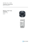
Universal master dimmer
Master Dimmer 6583-500
Electronic power module
6584-500
=== Ende der Liste für T extmar ke Cover ===
Operating Instructions
Busch-Dimmer ®
Pos : 4 /#N eus truktur #/Online-Dokumentation (+KN X)/Inhalts verz eic hnis (--> Für alle D okumente <--)/Inhalts verz eichnis @ 19\mod_1320649044386_15.doc x @ 109653 @ @ 1
1
2
3
4
5
6
7
8
9
10
Safety ....................................................................................................................................................................... 3
Intended use ............................................................................................................................................................ 3
Environment ............................................................................................................................................................. 3
Operation ................................................................................................................................................................. 4
4.1
Local operation ....................................................................................................................................... 4
4.1.1
Operation with push-button control element............................................................................................ 4
4.1.2
Operation with rotary control element ..................................................................................................... 5
4.1.3
Operation with timer control element....................................................................................................... 5
4.2
Programming using the function key ....................................................................................................... 6
4.3
Extended operation via control modules ................................................................................................. 6
Technical data.......................................................................................................................................................... 7
Setup and function ................................................................................................................................................... 8
6.1
Features of function and equipment ........................................................................................................ 8
6.2
Protective functions ................................................................................................................................. 8
6.3
Possible combinations ............................................................................................................................ 9
Reduction of the connection load (derating)........................................................................................................... 10
Installation and electrical connection ..................................................................................................................... 11
8.1
Requirements for the electrician ........................................................................................................... 11
8.2
Mounting ............................................................................................................................................... 12
8.3
Electrical connection ............................................................................................................................. 14
Commissioning ...................................................................................................................................................... 16
Fault rectification .................................................................................................................................................... 17
=== Ende der Liste für T extmar ke TOC ===
Operating Instructions | 1473-1-7939
—2—
Operating Instructions
Busch-Dimmer ®
Safety
Pos : 6 /#N eus truktur #/Online-Dokumentation (+KN X)/Ü bersc hriften (--> Für alle Dokumente <--)/1. Ebene/S - T/Sicherheit @ 18\mod_1302612791790_15.doc x @ 103357 @ 1 @ 1
1
Safety
Pos : 7 /#N eus truktur #/Online-Dokumentation (+KN X)/Sicherheits hinweis e und Hi nweis e (--> F ür all e D okumente <--)/Warnhinweis e/Sicherheit - 230 V @ 18\mod_1302606816750_15.doc x @ 103308 @ @ 1
Warning
Electric voltage!
Risk of death and fire due to electrical voltage of 230 V.
– Work on the 230V supply system may only be performed by authorised electricians!
– Disconnect the mains power supply prior to installation and/or disassembly!
Pos : 8 /#N eus truktur #/Online-Dokumentation (+KN X)/Ü bersc hriften (--> Für alle Dokumente <--)/1. Ebene/A - F/Bes timmungsgemäß er Gebrauc h @ 18\mod_1302763321316_15.doc x @ 103483 @ 1 @ 1
2
Intended use
Pos : 9 /#N eus truktur #/Online-Dokumentation (+KN X)/Bes timmungsgemäß er Gebrauc h (--> Für alle Dokumente <--)/Bus ch-Di mmer /Besti mmungsgemäß er Gebr auch @ 23\mod_1335350449857_15.doc x @ 208763 @ @ 1
The device is to be used exclusively with the components that are supplied and licensed as described in chapter
"Setup and function".
Pos : 10 /#Neustr uktur#/Online-Dokumentati on (+KN X)/Übersc hriften (--> Für all e D okumente <--)/1. Ebene/U - Z/U mwelt @ 18\mod_1302614158967_15.doc x @ 103383 @ 1 @ 1
3
Environment
Pos : 11 /#Neustr uktur#/Online-Dokumentati on (+KN X)/Sic herheits hinweise und Hinweis e (--> Für alle Dokumente <--)/Hinweis e - U mwelt/Hi nweis - U mwelt - Hi nweis El ektr ogeräte @ 18\mod_1302763973434_15.doc x @ 103500 @ @ 1
Consider the protection of the environment!
Used electric and electronic devices must not be disposed of with domestic waste.
– The device contains valuable raw materials which can be recycled. Therefore, dispose of the
device at the appropriate collecting depot.
Pos : 12 /#Neustr uktur#/Online-Dokumentati on (+KN X)/Sic herheits hinweise und Hinweis e (--> Für alle Dokumente <--)/Hinweis e - U mwelt/Hi nweis - U mwelt - Entsorgung Elektroger äte @ 20\mod_1325760695972_15.doc x @ 136583 @ @ 1
All packaging materials and devices bear the markings and test seals for proper disposal. Always dispose of the
packaging material and electric devices and their components via the authorized collecting depots and disposal
companies.
The products meet the legal requirements, in particular the laws governing electronic and electrical devices and
the REACH ordinance.
(EU Directive 2002/96/EC WEEE and 2002/95/EC RoHS)
(EU REACH ordinance and law for the implementation of the ordinance (EC) No.1907/2006)
Pos : 13 /#Neustr uktur#/Online-Dokumentati on (+KN X)/Steuer modul e - Online-Dokumentation (--> Für alle Dokumente <--)/++++++++++++ Seitenumbruc h ++++++++++++ @ 9\mod_1268898668093_0.doc x @ 52149 @ @ 1
Operating Instructions | 1473-1-7939
—3—
Operating Instructions
Busch-Dimmer ®
4
Operation
Operation
Pos : 14 /#Neustr uktur#/Online-Dokumentati on (+KN X)/Übersc hriften (--> Für all e D okumente <--)/1. Ebene/A - F /Bedi enung @ 11\mod_1279185541649_15.doc x @ 83043 @ 1 @ 1
Pos : 15 /#Neustr uktur#/Online-Dokumentati on (+KN X)/Bedi enung/Di mmer/Bedi enung - 6583 / 6584 @ 22\mod_1331904059330_15.doc x @ 203981 @ 233322 @ 1
4.1
Local operation
The master dimmer can also be operated onsite via exchangeable control elements.
Exchange of the standard cover against rotary dimmer control element, -push-button control element
or -timer control element.
6543/10 Tapping control element
6543/11 Rotary control element
6543/12 Timer control element
6583-…
Fig. 1:
4.1.1
Replaceable control elements
Operation with push-button control element
Activation
•
Tap briefly on the push-button.
The brightness value last set (memory value) will be automatically set.
Switch-on with basic brightness
•
Keep the push-button pressed.
The dimmer starts with the basic brightness and dims the light brighter as long as the push-button is pressed.
Dimming
•
Keep the push-button pressed.
The dimmer changes the brightness of the connected lighting system. With every stop, the dimming direction
is reversed. At maximum brightness, the dimmer stops; at minimum brightness, the dimming direction
changes.
Deactivation
•
Tap briefly on the push-button.
The current brightness value is saved as a memory value. The dimmer switches off immediately.
Operating Instructions | 1473-1-7939
—4—
Operating Instructions
Busch-Dimmer ®
4.1.2
Operation
Operation with rotary control element
Activation
•
Press the rotary button.
The brightness value last set (memory value) will be automatically set.
Turn-on with minimum brightness
•
Turn the rotary knob first to the left (approx. 45°) and then press it.
Switch-on with maximum brightness
•
Turn the rotary knob first to the right (approx. 45°) and then press it.
Brightness adjustment
•
Turn the rotary knob to the right or to the left while the dimmer is switched on.
Deactivation
•
With the dimmer being on, press the rotary button.
The dimmer switches off immediately.
Note
The rotary knob does not have a limit stop.
4.1.3
Operation with timer control element
The timer control element 6543/12 is used for automatic timer control. Manual control is only possible via
connected extension units or via the two upper buttons of the control element. Information on how to program the
timer can be found in the operating instructions for control element 6543/12.
Operating Instructions | 1473-1-7939
—5—
Operating Instructions
Busch-Dimmer ®
Operation
4.2
Programming using the function key
The following functions are activated by actuating the function key (1) for different periods of time.
Fig. 2:
Master Dimmer
1 Status display / function key
Green = Ready for operation
Red = Fault
Programming a brightness value
1. Set the desired brightness value with push-button or the rotary knob.
2. Then press the function key briefly (1).
Deleting the brightness value
1. Switch the dimmer off.
2. Then press the function key briefly (1).
Reset
•
Then press the function key (1) for more than 2 seconds.
The dimmer performs a load detection and is then reset to its delivery status.
4.3
Extended operation via control modules
®
A wide variety of switching and dimming functions can be performed conventionally via the ABB-i-bus or ABBPowernet-KNX using the control modules (6597, 6197/… and 6997/60).
Please refer to the relevant operating instructions, as well as to the latest functional descriptions in the technical
manuals and to the KNX product database.
Pos : 16 /#Neustr uktur#/Online-Dokumentati on (+KN X)/Steuer modul e - Online-Dokumentation (--> Für alle Dokumente <--)/++++++++++++ Seitenumbruc h ++++++++++++ @ 9\mod_1268898668093_0.doc x @ 52149 @ @ 1
Operating Instructions | 1473-1-7939
—6—
Operating Instructions
Busch-Dimmer ®
Technical data
Pos : 17 /#Neustr uktur#/Online-Dokumentati on (+KN X)/Übersc hriften (--> Für all e D okumente <--)/1. Ebene/S - T /Technisc he Daten @ 11\mod_1279185386320_15.doc x @ 83019 @ 1 @ 1
5
Technical data
Pos : 18 /#Neustr uktur#/Online-Dokumentati on (+KN X)/Technisc he Daten/Di mmer/Technisc he Daten - 6583/6584 @ 22\mod_1331902981743_15.doc x @ 203906 @ @ 1
Device-specific
6583
6584
Nominal voltage
230 V AC ± 10 %, 50 / 60 Hz
230 V AC ± 10 %, 50 / 60 Hz
Nominal power
500 W / VA
420 W / VA
Nominal power range
60 … 500 W / VA
200 … 420 W / VA
Capacity boosting
With a maximum of 6 electronic power
(depending on the ambient temperature, a
power loss of 5% in case of electronic and
20% for conventional transformers needs to
be considered)
modules (1200 … 2520 W / VA for
professional application)
Total output
A maximum of 3000 W / VA for
professional application
Nominal current
2,17 A
1,83 A
Push-button input
230 V AC ±10 %, 50 / 60 Hz (L or N)
–
Rotary dimmer input
230 V AC ±10 %, 50 / 60 Hz (L)
–
General
Maximum cable length
100 m
Maximum total cable length between the data
outputs
A maximum total cable length between the RJ
A maximum of 30 cm between devices, a maximum total of 2 m
12 connectors
Protection type
IP 20
Module width
2 MW (1 MW = 18 mm)
Total ambient temperature range
0 ...70 °C
Connected load
- Ambient temperature range
0° ... 45°C connected load 100 %
- Ambient temperature range
45° ... 70 C reduced connected load (Derating)
Note
Use the prefabricated RJ 12 data line to connect the devices. The data line is included in the
scope of supply of the electronic power module 6584.
Pos : 19 /#Neustr uktur#/Online-Dokumentati on (+KN X)/Steuer modul e - Online-Dokumentation (--> Für alle Dokumente <--)/++++++++++++ Seitenumbruc h ++++++++++++ @ 9\mod_1268898668093_0.doc x @ 52149 @ @ 1
Operating Instructions | 1473-1-7939
—7—
Operating Instructions
Busch-Dimmer ®
Setup and function
Pos : 20 /#Neustr uktur#/Online-Dokumentati on (+KN X)/Übersc hriften (--> Für all e D okumente <--)/1. Ebene/A - F /Aufbau und Funkti on @ 11\mod_1279185435352_15.doc x @ 83027 @ 1 @ 1
6
Setup and function
Pos : 21 /#Neustr uktur#/Online-Dokumentati on (+KN X)/Lastarten/Lastarten Gl üh | Halo | NV-Hal o mit konv-Trafo+ Elekt-Trafo @ 24\mod_1337859677891_15.doc x @ 213493 @ @ 1
The device is intended for the activation of the following types of loads:
230 V incandescent lamps
230 V halogen lamps
Low-voltage halogen lamps with conventional transformers
Low-voltage halogen lamps with electronic transformers
Pos : 22 /#Neustr uktur#/Online-Dokumentati on (+KN X)/Sic herheits hinweise und Hinweis e (--> Für alle Dokumente <--)/Hinweis e - Sachs chäden/Achtung - unz ul ässige Kombi von Tr afos @ 24\mod_1338794403191_15.doc x @ 215467 @ @ 1
Caution
Possible damage to the device due to an inadmissible combination of different types of
transformers!
Conventional and electronic transformers must not be dimmed together.
All other load combinations are permissible.
Pos : 23 /#Neustr uktur#/Online-Dokumentati on (+KN X)/Steuer modul e - Online-Dokumentation (--> Für alle Dokumente <--)/++++++++++++ 1 Leerzeil e Abs tand ++++++++++++ @ 24\mod_1337929289045_0.doc x @ 213673 @ @ 1
Pos : 24 /#Neustr uktur#/Online-Dokumentati on (+KN X)/Übersc hriften (--> Für all e D okumente <--)/2. Ebene/A - F /Funkti ons- und Aus stattungs mer kmal e @ 23\mod_1336557630140_15.doc x @ 209136 @ 2 @ 1
6.1
Features of function and equipment
Pos : 25 /#Neustr uktur#/Online-Dokumentati on (+KN X)/Aufbau und Funkti on/Di mmer/F unkti onen - 6583/6584 @ 22\mod_1331902756010_15.doc x @ 203891 @ 2 @ 1
Universal master dimmer
•
For the modular setup of an lighting system
•
Phase-angle / phase-section
•
Brightness control
•
Control via an attachable push-button / rotary / timer control element
•
Decentralised control via extension units (conventional push-buttons, e.g. 2020 US, or 2021/6 UK and rotary
dimmer extension unit 6592 U) or control modules.
•
Illumination of the push-button is only possible with N-conductor terminal
•
Reset, programming function
•
Light value storage (memory function)
•
Status display
•
Not suitable for generator networks
Electronic power module
•
Capacity boost via cable connected in parallel to the output side (with RJ12 plug) with electronic power
module 6584
•
In combination with up to 6 electronic power modules (3000 W/VA) possible.
6.2
•
•
•
•
Protective functions
Inrush current limitation through soft start
Electronic overload / excess temperature protection
Electronic short-circuit protection
Thermal fuse
Pos : 26 /#Neustr uktur#/Online-Dokumentati on (+KN X)/Steuer modul e - Online-Dokumentation (--> Für alle Dokumente <--)/++++++++++++ Seitenumbruc h ++++++++++++ @ 9\mod_1268898668093_0.doc x @ 52149 @ @ 1
Operating Instructions | 1473-1-7939
—8—
Operating Instructions
Busch-Dimmer ®
Setup and function
Pos : 27 /#Neustr uktur#/Online-Dokumentati on (+KN X)/Übersc hriften (--> Für all e D okumente <--)/2. Ebene/G - L/Kombinati ons möglichkeiten @ 19\mod_1320312769153_15.doc x @ 109520 @ 2 @ 1
6.3
Possible combinations
Pos : 28 /#Neustr uktur#/Online-Dokumentati on (+KN X)/Kombi nations möglichkeiten/Di mmer/Kombinati ons möglichkeiten - 6583/6584 @ 22\mod_1331903707363_15.doc x @ 203936 @ @ 1
6583
6584
X
X
2020 US
6583
X
2021/6 UK
X
6597
X
6584
X
6543/10
X
6543/11
X
6543/12
X
6997/60
Pos : 29 /#Neustr uktur#/Online-Dokumentati on (+KN X)/Steuer modul e - Online-Dokumentation (--> Für alle Dokumente <--)/++++++++++++ Seitenumbruc h ++++++++++++ @ 9\mod_1268898668093_0.doc x @ 52149 @ @ 1
Operating Instructions | 1473-1-7939
—9—
Operating Instructions
Busch-Dimmer ®
Reduction of the connection
load (derating)
Pos : 30 /#Neustr uktur#/Online-Dokumentati on (+KN X)/Übersc hriften (--> Für all e D okumente <--)/1. Ebene/A - F /Der ati ng @ 19\mod_1311253981718_15.doc x @ 107963 @ 1 @ 1
7
Reduction of the connection load (derating)
Pos : 31 /#Neustr uktur#/Online-Dokumentati on (+KN X)/Der ati ng/Der ating - Leistungs minderung (REG) @ 24\mod_1338555214091_15.doc x @ 214758 @ @ 1
The devices heat up during operation because part of the connected load is lost and converted into heat. If the
ambient temperature rises above 45°C during operation, the connected load must be reduced in accordance with
the diagram.
With a distance of approximately 1 cm between the devices or the installation of a heat distribution fan the
ambient temperature can be effectively reduced.
Pos : 32 /#Neustr uktur#/Online-Dokumentati on (+KN X)/Der ati ng/Der ating - Berec hnung Nennleistung el eltronisc he- konventi onelle Trafos @ 20\mod_1327415459238_15.doc x @ 137113 @ @ 1
Use the following formula for the calculation of the nominal power:
Nominal power = transformer losses* + lamp power
* 5% of the nominal transformer power in the case of electronic transformers
* 20% of the nominal transformer power in the case of conventional transformers
Pos : 33 /#Neustr uktur#/Online-Dokumentati on (+KN X)/Der ati ng/Der ating - Kur ve -- 45-70 -- Kur ve @ 24\mod_1338555953222_15.doc x @ 215433 @ @ 1
Fig. 3: Derating
Unit
Meaning
%
Percentage value of nominal power
°C
Ambient temperature
Pos : 34 /#Neustr uktur#/Online-Dokumentati on (+KN X)/Steuer modul e - Online-Dokumentation (--> Für alle Dokumente <--)/++++++++++++ Seitenumbruc h ++++++++++++ @ 9\mod_1268898668093_0.doc x @ 52149 @ @ 1
Operating Instructions | 1473-1-7939
— 10 —
Operating Instructions
Busch-Dimmer ®
Installation and electrical
connection
Pos : 35 /#Neustr uktur#/Online-Dokumentati on (+KN X)/Übersc hriften (--> Für all e D okumente <--)/1. Ebene/M - O/M ontage und el ektrisc her Anschl uss @ 23\mod_1336477157864_15.doc x @ 209033 @ 1 @ 1
8
Installation and electrical connection
Pos : 36 /#Neustr uktur#/Online-Dokumentati on (+KN X)/Sic herheits hinweise und Hinweis e (--> Für alle Dokumente <--)/Warnhinweise/Sic herheit - Ni eders pannungs- und 230 V-Leitungen @ 23\mod_1336558868201_15.doc x @ 209164 @ @ 1
Warning
Electric voltage!
Risk of death due to electrical voltage of 230 V during short-circuit in the low-voltage line.
– Low-voltage and 230 V lines must not be installed together in a flush-mounted socket!
Pos : 37 /#Neustr uktur#/Online-Dokumentati on (+KN X)/Sic herheits hinweise und Hinweis e (--> Für alle Dokumente <--)/Warnhinweise/Sic herheit - F ac hkenntniss e @ 23\mod_1336559183027_15.doc x @ 209179 @ 2 @ 1
8.1
Requirements for the electrician
Warning
Electric voltage!
Install the device only if you have the necessary electrical engineering knowledge and experience.
•
Incorrect installation endangers your life and that of the user of the electrical system.
•
Incorrect installation can cause serious damage to property, e.g. due to fire.
The minimum necessary expert knowledge and requirements for the installation are as follows:
•
Apply the "five safety rules" (DIN VDE 0105, EN 50110):
1. Disconnect from power;
2. Secure against being re-connected;
3. Ensure there is no voltage;
4. Connect to earth and short-circuit;
5. Cover or barricade adjacent live parts.
•
Use suitable personal protective clothing.
•
Use only suitable tools and measuring devices.
•
Check the supply network type (TN system, IT system, TT system) to secure the following
power supply conditions (classic connection to ground, protective earthing, necessary
additional measures, etc.).
Pos : 38 /#Neustr uktur#/Online-Dokumentati on (+KN X)/Steuer modul e - Online-Dokumentation (--> Für alle Dokumente <--)/++++++++++++ Seitenumbruc h ++++++++++++ @ 9\mod_1268898668093_0.doc x @ 52149 @ @ 1
Operating Instructions | 1473-1-7939
— 11 —
Operating Instructions
Busch-Dimmer ®
Installation and electrical
connection
Pos : 39 /#Neustr uktur#/Online-Dokumentati on (+KN X)/Übersc hriften (--> Für all e D okumente <--)/2. Ebene/M - O/M ontage @ 18\mod_1302615960458_15.doc x @ 103424 @ 2 @ 1
8.2
Mounting
Pos : 40 /#Neustr uktur#/Online-Dokumentati on (+KN X)/Sic herheits hinweise und Hinweis e (--> Für alle Dokumente <--)/Warnhinweise/Sic herheit - 230 V @ 18\mod_1302606816750_15.doc x @ 103308 @ @ 1
Warning
Electric voltage!
Risk of death and fire due to electrical voltage of 230 V.
– Work on the 230V supply system may only be performed by authorised electricians!
– Disconnect the mains power supply prior to installation and/or disassembly!
Pos : 41 /#Neustr uktur#/Online-Dokumentati on (+KN X)/Montage/alle Geräte/M ontage - H uts chi enen nac h D IN EN 500022 - Ohne Doc vari abl e @ 20\mod_1325766045140_15.doc x @ 136603 @ @ 1
The MDRC must only be installed on mounting rails according to DIN EN 500022. The MDRC is latched onto the
mounting rail.
Pos : 42 /#Neustr uktur#/Online-Dokumentati on (+KN X)/Sic herheits hinweise und Hinweis e (--> Für alle Dokumente <--)/Warnhinweise/War nung - Ü ber hitz ung durc h z u hohe Lasten @ 25\mod_1340618775008_15.doc x @ 220013 @ @ 1
Warning
Overheating due to excessive loads!
Incorrect installation can cause serious damage, e.g. due to fire.
Dimmer capacities > 1000 W are licensed only for professional use.
Ensure that there is adequate cooling.
Pos : 43 /#Neustr uktur#/Online-Dokumentati on (+KN X)/Sic herheits hinweise und Hinweis e (--> Für alle Dokumente <--)/Warnhinweise/War nung - Betri eb an Tr enntr ansfor matornetz e @ 24\mod_1338810453777_15.doc x @ 215529 @ @ 1
Warning
Risk of damage due to low connected load!
Operation with isolating transformer networks with a connected load of ≤ 10 kVA is not admissible.
Incorrect installation can cause serious damage to property, e.g. due to fire.
Observe the instructions regarding installation and electrical connection.
Pos : 44 /#Neustr uktur#/Online-Dokumentati on (+KN X)/Sic herheits hinweise und Hinweis e (--> Für alle Dokumente <--)/Hinweis e - Sachs chäden/Achtung - Ü ber hitz ung bei Transfor mator betrieb - konv. Tr afos @ 23\mod_1336481506967_15.doc x @ 209048 @ @ 1
Caution
Risk of damaging the device due to overheating!
When using transformers, ensure that each transformer is fused individually on the primary
side or with a thermal fuse according to the manufacturer's specifications.
Use exclusively wound safety isolating transformers according to DIN VDE 61558.
Pos : 45 /#Neustr uktur#/Online-Dokumentati on (+KN X)/Sic herheits hinweise und Hinweis e (--> Für alle Dokumente <--)/Hinweis e - Sachs chäden/Achtung - Z u hohe Ströme bei m Ei nsc halten @ 24\mod_1338797657109_15.doc x @ 215481 @ @ 1
Caution
Risk of damaging the device due to excessive current!
During reactivation of the load excessive currents and voltages can occur, which may lead to the
destruction of the device.
Switching the load via a serial switch contact is not admissible.
Pos : 46 /#Neustr uktur#/Online-Dokumentati on (+KN X)/Steuer modul e - Online-Dokumentation (--> Für alle Dokumente <--)/++++++++++++ Seitenumbruc h ++++++++++++ @ 9\mod_1268898668093_0.doc x @ 52149 @ @ 1
Operating Instructions | 1473-1-7939
— 12 —
Operating Instructions
Busch-Dimmer ®
Installation and electrical
connection
Pos : 47 /#Neustr uktur#/Online-Dokumentati on (+KN X)/Sic herheits hinweise und Hinweis e (--> Für alle Dokumente <--)/Hinweis e - Sachs chäden/Achtung - U nbelastete konventi onelle Trafos @ 24\mod_1338808686845_15.doc x @ 215495 @ @ 1
Caution
Risk of damaging the device due to excessive voltages!
Operation of an unloaded transformer connected to a dimmer may destroy both the transformer
and the dimmer. This is caused by a possible voltage rise which may occur between an unloaded
transformer and the dimmer.
Secondary-side idling of conventional transformers is permitted neither during commissioning
nor during operation.
Operate conventional transformers always at the nominal transformer load (derating).
Pos : 48 /#Neustr uktur#/Online-Dokumentati on (+KN X)/Sic herheits hinweise und Hinweis e (--> Für alle Dokumente <--)/Hinweis e - Allgemei n/Hi nweis - Transfor mator betrieb an Di mmern @ 23\mod_1336482230542_15.doc x @ 209074 @ @ 1
Note on operating transformers with dimmers
To achieve the same linear rise in the brightness level of halogen lamps over the entire adjusting
range from bright to dark, transformers with the same secondary voltage and the same power
should be used.
When installing, please bear in mind that transformers, depending on their quality and version,
may generate humming noise when used with dimmers.
Use an inrush current limiter if excessive inrush currents occur.
Pos : 49 /#Neustr uktur#/Online-Dokumentati on (+KN X)/Steuer modul e - Online-Dokumentation (--> Für alle Dokumente <--)/++++++++++++ Seitenumbruc h ++++++++++++ @ 9\mod_1268898668093_0.doc x @ 52149 @ @ 1
Operating Instructions | 1473-1-7939
— 13 —
Operating Instructions
Busch-Dimmer ®
Installation and electrical
connection
Pos : 50 /#Neustr uktur#/Online-Dokumentati on (+KN X)/Übersc hriften (--> Für all e D okumente <--)/2. Ebene/A - F /El ektrisc her Ansc hluss @ 21\mod_1328177051724_15.doc x @ 138042 @ 2 @ 1
8.3
Electrical connection
Pos : 51 /#Neustr uktur#/Online-Dokumentati on (+KN X)/Ansc hlus s/Di mmer/Ansc hluss - 6583/6584 @ 22\mod_1331905839399_15.doc x @ 204011 @ @ 1
Mains and load connection
The mains connection takes place at terminals L and N. As an option the is also connected to one of the terminals
(controlled outputs).
Push-button operation (terminal 1)
Any number of push-buttons (e.g., 2020 US) can be connected in parallel for switching and dimming of a master
dimmer 6583 via "terminal 1" push-button input. Sensing is carried out selectively to L or N. The common
activation of several dimmers via a push-button or rotary dimmer extension unit 6592 U is not admissible.
Caution
Risk of short-circuit!
Please note that during push-button operation the phase of the extension unit and the phase
of the supply voltage must be the same.
Information for connection
•
For all push-button extension units do not connect the lighting glow lamp with parallel
contacts. Instead, use a push-button with an N-connection.
•
When laying lines, ensure that there is sufficient distance between the control lines and load
lines (at least 5 cm).
6583
Fig. 4:
6584
Capacity booster of master dimmer 6583 with electronic power module 6584, push-button operation
1 Data line RJ12 (25 cm)
2 Extension unit, e.g. 2020 US (NO contact push-button)
3 Control modules 6597, 6997/60, 6197/11- ...
Note
For the joint dimming and switching of several master dimmers 6583 and for polyphase operation
/ individual or central controls, use control module 6597 / 6197/11- … or 6997/60.
Operating Instructions | 1473-1-7939
— 14 —
Operating Instructions
Busch-Dimmer ®
Installation and electrical
connection
Rotary dimmer operation (terminal 2)
For dimming via the dimmer input (terminal 2), up to 5 rotary dimmer extension units 6592 U can be connected.
6592 U
6583
6584
Power booster of master dimmer 6583 with electronic power module 6584, dimmer operation
1 Data line RJ12 (25 cm)
2 Dimmer extension unit (maximum of 5 extension units on the one dimmer)
3 Optional connection of neutral conductor on 6592 U
4 Control modules 6597, 6997/60, 6197/11- ...
Note on the connection of control modules
If a control module is connected, the on-site operation and the extension units are automatically
locked.
Data line (terminal D)
To switch and dim via the data line at terminal D, the dimmer can be operated via control modules. The following
®combinations for control via ABB-i-bus KNX or ABB-Powernet-KNX are possible:
Control through
Article number
Conventional
Control module 6597
ABB-i-bus ®-KNX
Control module 6197/11- ...
ABB-Powernet-KNX
Control module 6997/60
Note
Wiring diagrams can be found in the operating manuals of the devices.
•
Keep the data line as short as possible.
Capacity boosting
For synchronous switching and dimming of one lighting system with a connected load of more than 500 VA, a
capacity booster is used.
1. Connect dimmer 6583 and electronic power module 6584 via the RJ12 data line; see Fig. 4 and Fehler!
Verweisquelle konnte nicht gefunden werden..
The RJ12 data line is supplied together with the electronic power module.
2. Connect the outputs
of master dimmer 6583 to those of electronic power module 6584.
3. Always connect the load line to the last electronic power module.
Pos : 52 /#Neustr uktur#/Online-Dokumentati on (+KN X)/Steuer modul e - Online-Dokumentation (--> Für alle Dokumente <--)/++++++++++++ Seitenumbruc h ++++++++++++ @ 9\mod_1268898668093_0.doc x @ 52149 @ @ 1
Operating Instructions | 1473-1-7939
— 15 —
Operating Instructions
Busch-Dimmer ®
Commissioning
Pos : 53 /#Neustr uktur#/Online-Dokumentati on (+KN X)/Übersc hriften (--> Für all e D okumente <--)/1. Ebene/G - L/Inbetriebnahme @ 11\mod_1279185496977_15.doc x @ 83035 @ 1 @ 1
9
Commissioning
Pos : 54 /#Neustr uktur#/Online-Dokumentati on (+KN X)/Inbetriebnahme/Di mmer/Inbetriebnahme - 6583/6584 @ 22\mod_1331903887347_15.doc x @ 203966 @ @ 1
Universal master dimmer
After connecting the supply voltage, the microprocessor integrated in the dimmer evaluates the characteristics of
the connected service load and decides whether phase-angle or phase-section control is to be employed. During
this calibration process, the lighting system switches on for up to 2 seconds and the device is blocked.
Caution
Risk of malfunction due to inadmissible connection of loads!
To guarantee precise load detection by the dimmer, it must not be operated with a short circuit or
with secondarily idling, conventional transformers when the mains voltage is switched on.
After the load has been determined, the colour of the status display changes to green.
Pos : 55 /#Neustr uktur#/Online-Dokumentati on (+KN X)/Steuer modul e - Online-Dokumentation (--> Für alle Dokumente <--)/++++++++++++ Seitenumbruc h ++++++++++++ @ 9\mod_1268898668093_0.doc x @ 52149 @ @ 1
Operating Instructions | 1473-1-7939
— 16 —
Operating Instructions
Busch-Dimmer ®
Fault rectification
Pos : 56 /#Neustr uktur#/Online-Dokumentati on (+KN X)/Übersc hriften (--> Für all e D okumente <--)/1. Ebene/S - T /Stör ungs bes eitigung @ 18\mod_1308568208399_15.doc x @ 107037 @ 1 @ 1
10
Fault rectification
Pos : 57 /#Neustr uktur#/Online-Dokumentati on (+KN X)/Stör ungs bes eitigung/Di mmer/Störungsbes eitigung - 6583/6584 @ 22\mod_1331904478311_15.doc x @ 203996 @ @ 1
Diagnosis
Possible cause
Fault rectification
Light is permanently set to maximum
Basic brightness is set too high
Reduce basic brightness
brightness
Glow lamp is inserted in push-button
Remove illumination from pushbutton
extension with parallel contacts
extension
–
Perform a reset
Light cannot be switched on, status display
Fuse defective
Reconnect/replace line-side fuse
is “off”
In correct connection of supply lines /
Check and, if necessary, connect supply
wiring
lines / wiring correctly
Dimmer / electronic power module are
Replace defective dimmer / electronic
defective
power module
Light cannot be switched on, status display
Lamp is defective
Replace lamp
“green”
Transformer is defective
Check transformer and replace if
Light cannot be switched on, status display
Short-circuit
Remedy short-circuit of the load
Light automatically reduces brightness or
Overload
Reduce load in case of overload
switches off, status display "red"
Overheating
Improve heat dissipation by distributed
necessary
“red”
ventilation
Increase distance between devices
Light flickers
ELA system hums
Load is too low
Observe the minimum load
Fluctuation in mains voltage
Check fluctuation in mains voltage
Input network interference suppression
Check booster
defective
Stereo system / audio station system hums
Distance between the dimmer line and a
Increase distance to at least 10 cm
parallel amplifier line too short.
Note
After rectifying the fault and, if necessary, cooling of the device (approx. 30 minutes), press the
function key briefly.
•
The status display changes from red to green.
•
The dimmer is ready.
=== Ende der Liste für T extmar ke Content ===
Operating Instructions | 1473-1-7939
— 17 —
Operating Instructions
Busch-Dimmer ®
A member of the ABB Group
Busch-Jaeger Elektro GmbH
PO box
58505 Lüdenscheid
Freisenbergstraße 2
58513 Lüdenscheid
Germany
www.BUSCH-JAEGER.com
[email protected]
Central sales service:
Phone:
+49 (0) 2351 956-1600
Fax:
+49 (0) 2351 956-1700
Notice
We reserve the right to at all times make
technical changes as well as changes to the
contents of this document without prior notice.
The detailed specifications agreed to at the time
of ordering apply to all orders. ABB accepts no
responsibility for possible errors or
incompleteness in this document.
We reserve all rights to this document and the
topics and illustrations contained therein. The
document and its contents, or extracts thereof,
must not be reproduced, transmitted or reused by
third parties without prior written consent by ABB.
Copyright© 2012 Busch-Jaeger Elektro GmbH
All rights reserved
=== Ende der Liste für T extmar ke Bac kc over ===
1473-1-7939 | Rev. 01 | 17.12.2012
Pos : 59 /#Neustr uktur#/Online-Dokumentati on (+KN X)/Rüc ksei ten (--> Für alle Dokumente <--)Rüc ks eite - Busc h-J aeg er - Allgemein (2013-01-03 09:23:43) @ 28\mod_1347009779995_15.doc x @ 232282 @ @ 1