1
OPERATING INSTRUCTIONS
To select TV first press the CD/TV button on
the bottom row, then press the top right button
(shown on screen as source) then use the
large round rotary button to select TV from the
on screen list (should list CD, MP3, TV)
When the “Video in motion” feature is active
the Navigation may become slightly inaccurate. To solve this the DOUBLE PRESS the
VOLUME button of the steering wheel controls, the unit will then display the safety message and it will no longer be possible to view
TV on the move. To re-activate repeat the
process.
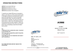
VWAV3
AV INPUT & VIDEO IN MOTION
VW / AUDI DVD Based RNS-E
Without TV Tuner
NAV TV (UK) LTD
NAV TV (UK) LTD
Unit R4
Capital Business Park
Wentloog
Cardiff
CF3 2PU
Telephone: + 44 (0)870 801 0440
Fax telephone: + 44 (0)870 801 0441
[email protected]
Disclaimer
NAV TV (UK) Ltd is not liable for any incidental, consequential or indirect damages. In case of erratic behavior of the vehicle’s electrical
system please disconnect the NAV TV product and contact our technical support Team. NAV TV (UK) Ltd does not assume liability for any
diagnostic fees.
e11*72/245*95/54*3583*00
e11*72/245*2004/104*4020*00
RoHS 2002/95/EC—2002/96/EC
LOCATION & REMOVAL
Installation is made at the front unit for both
“video in motion” and A/V input parts.
The unit is removed using 4 AUDI/VW removal keys.
Removing the unit without the correct keys
may cause damage and problems when refitting the unit.
INSTALLATION
INSTALLATION
AV Input
“Video In Motion”
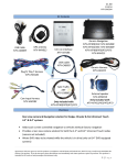
1.Insert supplied NAVTV 32 pin BLUE plug to GREY
socket on Head Unit, see fig 001& 002
Remove the “Quadlock” connector from unit and plug
into NAVTV harness, plug NAVTV harness into unit.
1. Connect Video lead to socket on Interface, see fig
001
2.Connect Audio leads to RED/BLACK cable sockets, see 002 (4)
Any additional plugs that are inserted into the car’s
“Quadlock” connector will have to be removed and inserted into the NAVTV “Quadlock” connector as shown
in fig 004 below.
3. Connect RED to 12v+ ignition/accessory
4. Connect BLACK to 12v- Ground
Fig 004
Fig 001
Fig 003
Fig 002