1
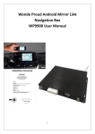
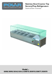
DS, BM 3/10/14 NTV-DOC094 Kit Contents USB Cable NTV-CAB009 GPS antenna NTV-NAV012 UCI-11c interface NTV-ASY180 LVDS cable NTV-CAB055 Plug N’ Play T Harness NTV-HAR182 NAV-Traffic ANT NTV-CAB063 Cam Input Harness NTV-HAR183 Only Included with: NTV-KIT469/470/472/473 Garmin Navigation NTV-KIT409/410: NTV-NAV008 NTV-KIT452/453: NTV-NAV009 NTV-KIT469/470/472/473: NTV-NAV015 Garmin Harness NTV-HAR225 External speaker NTV-HDW010 Only Included with: NTV-KIT452/453/472/473 Overview Rear view camera & Navigation solution for Dodge, Chrysler & Fiat UConnect Touch 4.3” & 8.4” systems Adds touch screen controlled navigation to vehicles without factory navigation Provides a rear view camera solution for both the 4.3” and 8.4” UConnect Touch radios (camera not included) Allows DVD video to be viewed while the vehicle is in drive (only on 8.4” DVD equipped systems) Agreement: End user agrees to use this product in compliance with all State and Federal laws. NAV-TV Corp. would not be held liable for misuse of its product. If you do not agree, please discontinue use immediately and return product to place of purchase. This product is intended for off-road use and passenger entertainment only. 2|Page DS, BM 3/10/14 NTV-DOC094 UCI-11c Connector Layout Rev 5 (Bluetooth or external speaker) Navigation Harness USB Update port Radio T-Harness Activity LEDs Rear view camera input LVDS cable TO SCREEN LVDS cable TO RADIO UCI-11c Pin Outs PIN # 1 2 3 4 5 6 7 8 Description Shield Shield Shield DIFF SIG (+) Video 3 Signal Video 2 Signal Video 1 Signal DIFF SIG (-) Color ---Gray/Orange Yellow White Green Gray/Blue Rear Camera Connector Wire Side View Agreement: End user agrees to use this product in compliance with all State and Federal laws. NAV-TV Corp. would not be held liable for misuse of its product. If you do not agree, please discontinue use immediately and return product to place of purchase. This product is intended for off-road use and passenger entertainment only. 3|Page DS, BM 3/10/14 NTV-DOC094 UCI-11c Pin Outs Continued PIN # 1 2 3 5 6 7 8 12 13 14 15 20 21 22 23 24 Description 12v (+) OUT ACC (+) OUT RX IN RGB B SIG RGB G SIG RGB R SIG RGB SYNC SIG HIGH-RES WIRE Ground MUTE IN TX OUT 3.5mm Shield 3.5mm Signal Audio Ground IN Audio Left IN Audio Right IN Color Yellow Red Blue Yellow Brown Red Black Gray Black White Yellow Black White Red Black Purple PIN # 1 2 3 4 5 6 7 8 9 10 11 12 13 14 15 16 17 18 Description 12v (+) Power Audio Ground OUT (RADIO) Audio Right OUT (RADIO) Audio Left OUT (RADIO) Reverse Trigger (+) IN Infotainment CAN HI (Radio) Infotainment CAN HI (Screen) Vehicle CAN HI (Car) Vehicle CAN HI (Radio) Ground (-) Audio Ground IN (CAR) Audio Right IN (CAR) Audio Left IN (CAR) 12v (+) OUT (1 amp) Infotainment CAN LO (Radio) Infotainment CAN LO (Car) Vehicle CAN LO (Car) Vehicle CAN LO (Radio) 24-PIN Navigation Connector Wire Side View Color Yellow White Gray Green Red Lt Blue Purple/Black Pink Blue/White Black White Gray Green Blue Brown Purple Pink/Black Blue 18-PIN Radio T-Harness connector Wire Side View Agreement: End user agrees to use this product in compliance with all State and Federal laws. NAV-TV Corp. would not be held liable for misuse of its product. If you do not agree, please discontinue use immediately and return product to place of purchase. This product is intended for off-road use and passenger entertainment only. 4|Page DS, BM 3/10/14 NTV-DOC094 UCI Installation REQUIRED - Phillips head screwdriver - Plastic pry tool - Small pocket screwdriver *Refer to online document for vehicle specific installation* 1. Detailed disassembly instructions for the 300, Charger, Dart and Journey are available at http://navtv.com/page/17/manuals.html under the Video Input and Backup Camera section. 2. Gain access to the back of the radio head. Pull out the radio enough to access the wiring behind the radio. 3. Disconnect the factory white 22 pin connector from behind the radio/gateway. This connector supplies Power and ground as well CAN communication to the radio. 4. In the kit is a 22 pin T-harness. Connect the removed harness from the radio to the female receptacle of the supplied harness. Take care not to bend any of the pins in the female receptacle when inserting. 5. Plug the male plug of the T-harness into the radio where the factory connector was located. If any other cables were disconnected when the radio was removed, plug them back into the radio. Slide the radio gently back into the opening and route the extension harness with the 18 pin connector up behind the monitor. Do not secure the radio with the factory screws until the installation has been completed and tested. Agreement: End user agrees to use this product in compliance with all State and Federal laws. NAV-TV Corp. would not be held liable for misuse of its product. If you do not agree, please discontinue use immediately and return product to place of purchase. This product is intended for off-road use and passenger entertainment only. 5|Page DS, BM 3/10/14 NTV-DOC094 6. Using the plastic pry tool, gently pry around the dash panel surrounding the monitor to release the locking tabs. Take extra care when releasing these tabs, they may fall from the dash panel and into the dash. 7. Gain access to the rear of the screen & disconnect the 3 cables that are attached. PAY ATTENTION TO THE WHITE CIRCULAR 4 PIN PLUG. THIS PLUG WILL BE INSERTED INTO THE UCI IN LATER STEPS. IF YOU INSERTED ANYTHING AT THE RADIO INTO THE UCI AT THIS STAGE PUT THE VEHICLE BACK TO STOCK AND START AGAIN AT INSTRUCTION 1. 8. Set the monitor and/or dash assembly aside. 9. The free end of the T-harness that is plugged into the radio head (18 pin connector) should have been routed behind the monitor in step 4. If not, do it now. 10. Insert the 18 pin connector into the port labeled “Radio T-harness” of the UCI. 11. Locate the WHITE, ROUND connector that was removed from the screen in step 7. Insert this cable into the WHITE port of the UCI labeled “LVDS IN”. 12. Take the provided aftermarket LVDS cable (#3 on the product description on page 1) and insert the BLACK end into the BLACK port of the UCI (LVDS OUT). The other end will be connected to the screen later. 13. If installing a rear view camera, insert the 8 pin MOLEX plug into the port labeled “Video IN”. Of the connections available, there’s; a. Twisted Pair – Used for factory installed camera only on the 4.3” screens. This input is not used on the 8.4” screens. On the 8.4” screens, the factory camera input is on the back of the radio head. b. Video 1, 2 & 3- Used for an aftermarket camera input using composite video (yellow RCA connection). *Power connections for the rear view camera must be made at the cigarette lighter. 14. If installing navigation into the system, proceed to the navigation installation section. Otherwise continue to step 15. 15. After all the connections are made, securely mount the UCI module in the dash. 16. Connect the WHITE end of the provided LVDS cable into the screen. Make all other connections and temporarily reassemble the radio, screen and the HVAC controls. Do not reassemble permanently until the system has been thoroughly checked 17. THIS SYSTEM REQUIRES AN INITIAL SETUP PROCEEDURE PRIOR TO FUNCTIONING CORRECTLY. PROCEED TO EITHER THE 4.3" SETTING SECTION ON PAGE 8 OR THE 8.4" SETTINGS SECTION ON PAGE 11 DEPENDING ON WHICH SIZE MONITOR IS IN YOUR VEHICLE. 18. After making the necessary changes in the SETUP menu, test the system and reassemble. If Installing Navigation Once you complete step 13 of the UCI installation, continue from this point. 1. Plug in the supplied 24 pin Navigation harness into the port on the UCI labeled NAVIGATION/AV. Agreement: End user agrees to use this product in compliance with all State and Federal laws. NAV-TV Corp. would not be held liable for misuse of its product. If you do not agree, please discontinue use immediately and return product to place of purchase. This product is intended for off-road use and passenger entertainment only. 6|Page DS, BM 3/10/14 NTV-DOC094 2. Route this cable down to the location where you will be installing the NTX54 navigation unit. Be sure to securely fasten it to existing wiring and brackets and route it away from any sharp or moving parts. 3. After all the connections have been made to the UCI module it is time to mount it. We recommend using the large space available behind the monitor in the dash cavity and securing it with Velcro. For added stability, a large zip tie should be used to secure the module in place. 4. Plug the routed cable from the UCI into the NTX54 navigation unit at the power connector. 5. If installing a REV5 product and the vehicle has FACTORY BLUETOOTH, skip to step 8. If you are installing a REV3 product OR if the vehicle does not have FACTORY BLUETOOTH continue with step 6. 6. Included in the kit is an external speaker, it is used for turn by turn navigation or any audio output from the navigation unit. The speaker can be mounted on one of the metal rails running vertically under the steering column. It is recommended that the speaker faces the opening under the steering column for best volume. 7. Plug the speaker into the 3.5mm jack on the UCI to navigation harness. 8. The GPS antenna needs to be installed, right side up, in a location that has a clear line of sight of the sky. The antenna can be mounted on the dash, or located in the dash below the dash pad without any metal obstructions. Be sure the antenna is securely mounted with Velcro, 2 sided stick tape or a metal surface. 9. Connect the antenna to the jack labeled GPS ANT on the navigation unit. 10. Return to step 15 in the UCI installation instructions and then proceed to the SETTINGS section for your screen size. GPS Antenna connector Power connector NAV-Traffic Antenna port (Only for NTV-KIT469/470/472/473 Agreement: End user agrees to use this product in compliance with all State and Federal laws. NAV-TV Corp. would not be held liable for misuse of its product. If you do not agree, please discontinue use immediately and return product to place of purchase. This product is intended for off-road use and passenger entertainment only. 7|Page DS, BM 3/10/14 NTV-DOC094 UCI Settings 4.3” Monitor Adjusting the rearview camera settings PRIOR TO ADJUSTING ANY SETTING AFTER THE INITIAL INSTALLATION, TURN THE VEHICLE OFF, CLOSE ALL DOORS, THE HOOD AND TRUNK AND LOCK THE VEHICLE WITH THE FACTORY KEY FOB OR LOCK IT WITH THE KEY. WAIT ONE MINUTE AND THEN UNLOCK THE VEHICLE AND PROCEED WITH THE FOLLOWING STEPS. EVEN IF YOU ARE NOT INSTALLING A CAMERA YOU MUST PERFORM THESE STEPS. To access the settings screen, press and hold the “Settings” button on the upper right of the 4.3" monitor for 3 seconds. On the touch screen, press “Camera Input Settings” to select it... Adjusting the input: - Touch the “Input” soft key - Every press of the icon will change the input; OFF, DIFF (factory camera), Video 1, Video 2, Video 3. The input image will be displayed in the back ground once the correct input is selected. - IF NO CAMERA IS BEING INSTALLED SELECT OFF AND THEN EXIT Adjusting brightness: - Touch the “Brightness” soft key. - Press the “-“or “+” soft key to adjust the image in 10% increments. - Press the “Exit” soft key. Adjusting Contrast: - Touch the “Contrast” soft key. - Press the “-“or “+” soft key to adjust the image in 10% increments. - Press the “Exit” soft key. Adjusting the Saturation: - Touch the “Saturation” soft key. - Press the “-“or “+” soft key to adjust the image in 10% increments. - Press the “Exit” soft key. - To exit the Camera Input Setting, press the “Exit” soft key. Agreement: End user agrees to use this product in compliance with all State and Federal laws. NAV-TV Corp. would not be held liable for misuse of its product. If you do not agree, please discontinue use immediately and return product to place of purchase. This product is intended for off-road use and passenger entertainment only. 8|Page DS, BM 3/10/14 NTV-DOC094 NOTE: IF NO NAVIGATION IS BEING INSTALLED SELECT "NAVIGATION INPUT SETTINGS" FROM THE MAIN SCREEN AND FOLLOW THE DIRECTIONS BELOW TO SELECT THE NAVIGATION SETTING TO OFF. Adjusting the navigation settings (if installed) On the touch screen, press “Navigation input settings” to select it. Adjusting the input: - Touch the “Input” soft key - Every press of the icon will change the input; OFF, RGB, Video 1, Video 2, Video 3. The input image will be displayed in the back ground. - The proper setting for ALL supported navigation devices is RGB. Presently video 1, 2 & 3 are not supported. If only a camera is being installed and you turned the input to off, make sure to select exit from the "navigation settings" screen and then again from the main screen to save the settings. If a navigation system is being installed proceed to the section below, "setting the correct navigation system" without exiting from the "navigation settings screen". Selecting the correct Navigation System: - This step is CRITICAL as it determines both the resolution and the communication protocol of the navigation system. If you choose the wrong navigation system the resolution will be incorrect and the touch screen will not control the navigation system. - Touch the “Model” soft key to switch between 1 of 4 compatible navigation options. There are 4 navigation options available: NTX54-1, NTX54-2, KNA-G610 and WP. - NTX54-1: There is a white sticker on the NTX54 designating it as an NTX54-1. Select NTX54-1 with this navigation system. The NTX54-1 can ONLY be used with the 4.3" monitor. The loop on the plug that plugs in at the NTX54 navigation brain MUST BE CUT when using a 4.3" monitor - NTX54-2: The NTX54-2 is a resolution and communication setting only. It is actually used with the NTX54-3 navigation system on the 4.3". When using a NTX54-3 select NTX54-2 as the correct model. The NTX54-3 has a white sticker on the bottom to Agreement: End user agrees to use this product in compliance with all State and Federal laws. NAV-TV Corp. would not be held liable for misuse of its product. If you do not agree, please discontinue use immediately and return product to place of purchase. This product is intended for off-road use and passenger entertainment only. 9|Page DS, BM 3/10/14 NTV-DOC094 - identify it as an NTX54-3. The loop on the plug that plugs in at the NTX54 navigation brain MUST BE CUT when using a 4.3" monitor KNA-G610: Select this setting when using a Kenwood KNA-G610 navigation system. WP: Select this setting when using a Directus, Intraphex or Wonde Proud Navigation system. To exit the Navigation input setting, press the “Exit” soft key. To confirm the current hardware/software revision - - Press the “About” soft key to show the current software revision. The current software version is dated September 10, 2012. If your software is older than September 10, 2012 there is a free software update available at http://navtv.com/page/19/downloads.html labeled UCI-11C_Garmin updater 9/10/2012. A REV3 board will show hardware as 3RO and a REV5 will show 5RO. Press the “Exit” soft key to return to the main menu. Completing the Setup Procedure: VERY IMPORTANT!!!! - After you have setup the rear view camera, navigation and verified that the software in the UCI is current you will be back at the main screen. This screen shows UCI by NAV-TV, Camera input settings, navigation input settings and about. Below the "about" is the word "exit". In order to store all your setting you MUST press this exit button. If you switch modes during this process, turn off the vehicle or disconnect any cable the settings will not be saved and you will have to start over from step 1 again. - Put the vehicle to sleep by closing ALL doors, the hood and trunk and locking the car with the key fob or key and wait 1 minute. Agreement: End user agrees to use this product in compliance with all State and Federal laws. NAV-TV Corp. would not be held liable for misuse of its product. If you do not agree, please discontinue use immediately and return product to place of purchase. This product is intended for off-road use and passenger entertainment only. 10 | P a g e DS, BM 3/10/14 NTV-DOC094 - After 1 minute unlock the vehicle and check the system. For operation please refer to page 12 "reverse and navigation operation" 8.4” Monitor Adjusting the rearview camera settings PRIOR TO ADJUSTING ANY SETTING AFTER THE INITIAL INSTALLATION, TURN THE VEHICLE OFF, CLOSE ALL DOORS, THE HOOD AND TRUNK AND LOCK THE VEHICLE WITH THE FACTORY KEY FOB OR LOCK IT WITH THE KEY. WAIT ONE MINUTE AND THEN UNLOCK THE VEHICLE AND PROCEED WITH THE FOLLOWING STEPS. EVEN IF YOU ARE NOT INSTALLING A CAMERA YOU MUST PERFORM THESE STEPS. To access the settings screen, press and hold the “Power” button on the HVAC controller for 5 seconds. A menu will appear on the monitor after 5 seconds. On the touch screen, press “Camera Input Settings” to select it. Adjusting the input: o Touch the “Input” soft key o Every press of the icon will change the input; OFF, Head Unit (factory camera), Video 1, Video 2, Video 3. The input image WILL NOT be displayed in the back ground during the camera selection. o NOTE: The differential input at the UCI IS NOT USED WITH THE 8.4" monitor. o IF NO CAMERA IS BEING INSTALLED SELECT OFF AND THEN EXIT o IF THE VEHICLE HAS A FACTORY CAMERA YOU MUST SELECT HEAD UNIT OR THE CAMERA WILL NOT FUNCTION AFTER INSTALLATION AND YOU WILL BE REQUIRED TO FOLLOW THESE STEPS AGAIN. o If installing the Charger-Cam also select Head Unit. The Charger-Cam installs at the back of the radio, not the UCI. Please follow the included Charger-cam instructions. O To exit the Camera Input Setting, press the “Exit” soft key. NOTE: THE UCI IS NOT INTENDED AS JUST A REAR VIEW CAMERA INTEGRATION MODULE FOR THE 8.4" SYSTEM. IF YOU ARE ONLY INSTALLING A REAR VIEW CAMERA YOU SHOULD USE THE UCT84/NTV-KIT 297 and the UCT differential camera adapter/NTV-KIT314 instead. Agreement: End user agrees to use this product in compliance with all State and Federal laws. NAV-TV Corp. would not be held liable for misuse of its product. If you do not agree, please discontinue use immediately and return product to place of purchase. This product is intended for off-road use and passenger entertainment only. 11 | P a g e DS, BM 3/10/14 NTV-DOC094 Adjusting the navigation settings (if installed) o Press the “Navigation input settings” soft key. Adjusting the input: o Touch the “Navigation” soft key o Every press of the icon will change the input: OFF & ON. Only the RGB input is available. The input image will not be displayed in the back ground. Make sure that the "input" setting is selected to "ON". To exit the Navigation Input Settings, press the “Exit” soft key. !DO NOT SELECT EXIT AT THIS POINT FROM THE NAVIGATION INPUT SETTINGS SCREEN! YOU MUST SELECT THE PROPER NAVIGATION SYSTEM AS WELL AS THE COLOR ICON AND SCREEN RESOLUTION IN THE FOLLOWING SECTION! . Selecting the proper Navigation system o This step is CRITICAL as it determines the communication protocol of the navigation system. If you choose the wrong navigation system the touch screen will not control the navigation system. o Touch the “Model” soft key to switch between 1 of 4 compatible navigation options. There are 4 navigation options available: NTX54-1, NTX54-2, KNA-G610 and WP. o NTX54-1: This setting is NOT USED on the 8.4" and is only for future use. The NTX54-1 navigation system is not compatible with the 8.4" monitor. If you are attempting to install a navigation system in a vehicle with an 8.4" screen and the NTX54 has a white label that says "NTX54-1", STOP and contact the establishment you purchased the unit from and have the navigation exchanged. o NTX54-2: The NTX54-2 is a communication setting only. It is used with either the NTX54-2, NTX54-3 NTX54-4 navigation system on the 8.4". When using a NTX54-2/-3/-4, select NTX54-2 as the correct model. The NTX54-2 & NTX54-3 have a white sticker on the bottom for identification. NOTE: The NTX54-2 is used ONLY in 8.4" vehicle that have factory Bluetooth. The NTX54-3 can be used either with an external speaker OR in vehicles with factory Bluetooth. The loop on the plug that plugs in at the NTX54-2 or NTX54-3 navigation brain MUST BE INTACT and NOT CUT when using an 8.4" monitor. Agreement: End user agrees to use this product in compliance with all State and Federal laws. NAV-TV Corp. would not be held liable for misuse of its product. If you do not agree, please discontinue use immediately and return product to place of purchase. This product is intended for off-road use and passenger entertainment only. 12 | P a g e DS, BM 3/10/14 NTV-DOC094 o KNA-G610: Select this setting when using a Kenwood KNA-G610 navigation system. The loop on the plug that plugs in at the KNA-G610 navigation brain MUST BE INTACT and NOT CUT when using an 8.4" monitor. Once the proper Model Navigation has been selected you need to stay on the same screen and select the "Icon Color". o Touch the “Icon Color” soft key o Every press of the icon will change the icon: Red is used for the Dodge charger, Blue is used for the Chrysler 300 and Red Journey is used for the Dodge Journey. Once the proper icon has been selected press "Exit" to exit the Navigation input setting screen. Changing the Timing setting If after installation of the UCI with Garmin NAV the factory image is skewed in any way, try adjusting Timing to ‘Timing 2’ in the Navigation settings. * *Note: If timing is off from the get-go, touch screen accuracy for any button may be shifted about ½” beneath the actual visual image (words). Once the proper timing has been selected, press “Exit” to return to the main settings screen. Changing the Video in motion settings Press the “Video in Motion” soft key. o Touch the “Video in Motion” soft key to change status: On or OFF This function turns on or off the ability to watch DVD videos while the vehicle is in drive. o Press the “Exit” soft key to return to the main menu. To confirm the current hardware/software revision Press the “About” soft key to show current software revision. The current software version is dated September 10, 2012. If your software is older than September 10, 2012 there is a free software update available at http://navtv.com/page/19/downloads.html labeled UCI-11C_Garmin updater 9/10/2012. board will show hardware as 3RO and a REV5 will show 5RO. Completing the Setup Procedure: VERY IMPORTANT!!!! Agreement: End user agrees to use this product in compliance with all State and Federal laws. NAV-TV Corp. would not be held liable for misuse of its product. If you do not agree, please discontinue use immediately and return product to place of purchase. This product is intended for off-road use and passenger entertainment only. 13 | P a g e DS, BM 3/10/14 NTV-DOC094 After you have setup the rear view camera, navigation and verified that the software in the UCI is current you will be back at the main screen. This screen shows UCI by NAV-TV, Camera input settings, navigation input setting, video in motion and about. Below the "about" is the word "exit". In order to store all your setting you MUST press this exit button. If you switch modes during this process, turn off the vehicle or disconnect any cable the settings will not be saved and you will have to start from step 1 again. Put the vehicle to sleep by closing ALL doors, the hood and trunk and locking the car with the key fob or key and wait 5 minutes. After 5 minutes unlock the vehicle and check the system. For operation please refer to page 12 "reverse and navigation operation" UCI-11c Operation Rear View Camera The rear view surroundings will be displayed anytime the vehicle is shifted into REVERSE. The image will be displayed on the factory touch screen along with the text “Check Entire Surroundings”. The text will remain on the screen for 10 seconds and then will fade out. Once the vehicle is shifted out of REVERSE, the image will fade into the previous mode or screen. Do not rely completely on the rear camera image; periodically check your surroundings for obstacles. Navigation 4.3” monitor To display navigation, press the “Screen Off” button. This will display the navigation home page. To exit navigation press the Screen Off button again. Audio prompts will be heard through the external speaker. Refer to the navigation documentation for operation. 8.4” monitor When navigation is enabled, a new icon will show up in the bottom right corner of the screen, where the “More” soft key is located. This icon may take up to 10 seconds to appear once the vehicle has been unlocked. To access the navigation, press the “Nav” soft button on the lower right corner. The navigation screen will be displayed. All the functions of the navigation can be controlled through the factory touch screen. (Refer to the user manual for operation). To exit the navigation screen, press the desired source. The “More” soft touch button for the factory SETTINGS screen can be accessed through the navigation screen. While in navigation mode, if the climate control is adjusted the navigation screen will disappear anytime the system is being accessed. 3 seconds after the last operation, the navigation screen will return. Agreement: End user agrees to use this product in compliance with all State and Federal laws. NAV-TV Corp. would not be held liable for misuse of its product. If you do not agree, please discontinue use immediately and return product to place of purchase. This product is intended for off-road use and passenger entertainment only. 14 | P a g e DS, BM 3/10/14 NTV-DOC094 FAQs P1: I installed the piece and now the radio does not come on and the HVAC does not work. A1: Check to make sure that the T-harness is plugged in securely and that the mini molex is plugged into the UC1. A2: If plugged in, unplug the T-harness and do a visual inspection for bent pins or pins that have popped out. Align the pins or put them back into the correct position and reconnect the harness securely A3: Check for the REV3.1 sticker to verify the hardware is current for a REV3. If a REV5 does this remove one side and slide the board out. Check to see if the daughter card has become dislodged. Simply reseat the daughter card and retest. A4: Have the unit plugged into a computer to check to make sure that the software is current and correct for the application (AKA rev3 software in a REV5 or outdated software). Update the unit and retry. P2: I installed the piece and the radio comes on but there is a black screen. I cannot even get the factory screen to come on. A1: YOU DIDN'T READ THE DIRECTIONS AND INSTALLED THE VIDEO IN AND OUT AT THE RADIO INSTEAD OF AT THE SCREEN! Put the factory LVDS cable back to factory and verify that the factory image comes on. If it does put the radio back into the dash loosely and access s the back of the monitor. At this point NO LVDS CABLES SHOULD BE PLUGGED INTO THE UCI. IN ORDER, unplug the white LVDS cable at the back of the monitor and plug it into the white port on the UCI. Then plug the BLACK end of the included LVDS cable with a white and a black end into the UCI. Now plug the white end of the included cable into the monitor. Check for factory pass through. If good, proceed to programming. A2: If A1 didn't solve the problem and it is a REV5 board have them remove one end and reseat the daughter card and retest. A3: If nothing fixes the issue check for the proper software and update if needed. P3: I installed the piece and the factory rear view camera no longer works. A1: You did not set up the rear view camera settings after installation. Go into the settings menu and select rear view camera. Change the setting to "head unit". Select exit and exit again to store the setting. Perform a CAN reset and retest. P4: I cannot get into the settings menu at all. A1: Do a CAN reset and try again. A2: Check to make sure you have the proper software (4.3 or 8.4 rev3 or rev5) P5: I installed an aftermarket rear view camera and it doesn't work. A1: See P3 above and instead switch the input to a different setting and retest. A2: try a CAN reset after A1 is performed again. Agreement: End user agrees to use this product in compliance with all State and Federal laws. NAV-TV Corp. would not be held liable for misuse of its product. If you do not agree, please discontinue use immediately and return product to place of purchase. This product is intended for off-road use and passenger entertainment only. 15 | P a g e DS, BM 3/10/14 NTV-DOC094 P6: I installed an aftermarket or factory fit camera and the screen only goes to a black screen in reverse or the picture is wavy and distorted. A1: See p5 above and repeat. A2: You didn't power the rear view camera. Check power. A3: You selected the wrong input. A4: You powered the camera off of the reverse lights. Run camera power to the front cigarette lighter. A5: You attached the factory-fit camera wires backwards. Correct and retest. P6: The factory-fit camera works but it has a wavy line at the bottom of the screen. A1: You grounded the drain wire. Cut it loose and retest. A2: Do a CAN reset and retest BUT this time with the car RUNNING to check for a low voltage condition. P7: I installed the system and I get no image or a distorted image when trying to switch to navigation. A1: Make sure the proper navigation system has been selected. A2: If installing either a Kenwood or a NTX54 make sure that pin 8 on the Garmin plug is showing ground for an 8.4 or no connection and no ground for a 4.3". A3: Make sure the proper software is in the unit P8: The touch screen controls are not working on the unit BUT I can see a navigation screen. A1: You selected the wrong navigation type. Change the navigation model to the correct type and retry. Make sure to select exit and exit again. P9: Selections are not being stored correctly. A1: You are not selecting exit and exit again. A2: On some vehicles it requires a CAN reset before some settings will stick correctly. Perform a CAN reset and try again (close all doors, lock car and return/retest in 10 minutes). P10: I installed the Garmin or Kenwood system into a 4.3 and i get a distorted navigation picture. A1: Cut the wire in pin 8 on the Garmin harness and retest. You must put the UCI to sleep first as it will not allow a hot swap resolution change. Do a CAN reset and retest. P11: I installed the system into a vehicle without Bluetooth and I thought it had it. A1: Both the NTX54-1 and NTX54-3 are compatible with an external speaker. Only the NTX54-2 does not have the capability to power an external speaker. Check the version of the NTX54 to determine whether or not it is compatible. P12: My factory image and NAV image is distorted in general. A1: Try adjusting the ‘Timing’ setting in the NAV settings. Refer to 8.4” Screen settings. Agreement: End user agrees to use this product in compliance with all State and Federal laws. NAV-TV Corp. would not be held liable for misuse of its product. If you do not agree, please discontinue use immediately and return product to place of purchase. This product is intended for off-road use and passenger entertainment only. 16 | P a g e