1
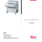
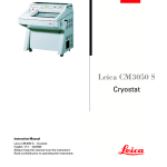
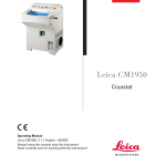
OPERATING
INSTRUCTIONS
Cryostat
MTC
INS2200GB
07-2010-04
Instructions – MTC
1
Instructions – MTC
2
CONTENTS
1. INTENDED USE
............................................................ 4
2. SYMBOLS
............................................................ 4
3. SAFETY NOTES
............................................................ 4
4. COMPONENTS
............................................................ 8
5. SPECIFICATIONS
............................................................ 9
6. UNPACKING AND INSTALLATION
............................................................ 10
7. INITIAL OPERATION
............................................................ 12
8. OPERATION OF MICROTOME
............................................................ 19
9. OPERATION OF CRYOSTAT
............................................................ 29
10. CLEANING AND MAINTENANCE
............................................................ 32
11. SERVICE
............................................................ 34
12. OPTIONAL ACCESSORIES
............................................................ 35
13. WARRANTY
............................................................ 36
14. DISPOSAL
............................................................ 36
Instructions – MTC
3
1. INTENDED USE
The bench top cryostat MTC is intended for rapid freezing and cutting thin sections of
frozen specimens for professional use in routine and research laboratories in the fields of
biology, medicine and industry.
The system of knife advance operates very reliable from 1 to 25 µm with trimming
function up to 25 µm. The MTC is an easily transportable instrument with space-saving
design which makes it the perfect alternative for locations with limited space, increased
mobility requirements or simply as an economic backup instrument.
2. SYMBOLS
Dangers, warnings and cautions are marked by this symbol
i
Special instructions regarding the operation of the
instrument are marked by this symbol
3. SAFETY NOTES
The SLEE Medical bench top cryostat MTC is provided with the following safety features:
MTC
Hand wheel stop
Finger protection for Knife- and blade-holder
•
•
The institution which owns the unit and the persons working with the unit, servicing or
repairing it have the responsibility for a hazard-free use.
Instructions – MTC
4
3.1 Hand wheel stop
Always use the finger protection
with the knife-/blade holder and put
hand wheel in stop position
•
before working with the
knife or specimen
•
before changing the
specimen
•
during break time
The hand wheel can be stopped in
any position. For this purpose move
the stop lever towards the centre.
For releasing the stop please turn
the lever towards the outside again.
Hand wheel stop released. Movement.
Hand wheel stop activated. No movement.
Instructions – MTC
5
3.2 FINGER PROTECTION
Use the finger protection always
•
Before you start any work with
the knife or specimen
•
Before changing the specimen
•
During work break
Finger protection released.
Finger protection activated.
Instructions – MTC
6
3.3 ELECTRICAL POWER CONNECTION
Do not use any extension lead.
Make sure that electric power is constant:
•
This should be examined during installation of the unit by a
competent person
•
Use a dedicated fuse for the unit
•
Do not connect another unit to the same power circuit.
•
Before turning on the instrument, check if the voltage of the mains
supply is identical with the name plate of the unit
3.4 WORKING WITH KNIVES AND DISPOSABLE BLADES
Microtome knives and disposable blades have extremely sharp edges and this can lead
to injuries.
Please be extremely careful when handling microtome knives and disposable blades.
Do not place microtome knives or disposable blades at unsecured areas.
Never position microtome knives or disposable blades with the sharp edge
pointing upwards.
Store blades in a covered container. Use a container that has guides to
hold the blades rigid.
Never try to catch a falling microtome knife.
Always insert the specimen first and then the microtome knife or
disposable blade.
To avoid compression or knife marks, ensure that the blade is clean.
Instructions – MTC
7
4. COMPONENTS
The SLEE bench top cryostat MTC is provided with the following standard components:
MTC
Basic unit with refrigeration system
•
Manual rotary microtome
•
Operation manual
•
2x Specimen holder
(1x Ø 22mm; 1x Ø 35 mm)
clear-cut
Brush
Anti-roll plate
Ready to use
•
•
•
1x Bottle cryostat low temperature oil
•
4x 100 ml CryoGlue embedding medium
•
1 Box of disposable blades (50 pcs.) or 1
steel knife (12 cm C-profile)
•
Set of Allen keys
•
Instructions – MTC
8
5. SPECIFICATIONS
Operating temperature range
+10 °C to +25 °C
Section thickness setting range
1 - 25 µm
Section thickness selection
MTC
0 – 10 µm in 1-µm-steps
10 - 25 µm in 5-µm steps
Horizontal specimen advance
25 mm
Vertical specimen stroke
52 mm
Dimensions and weight
550 mm x 730 mm x 470 mm
[width x depth x height]
77 kg
Weight
without accessories
Specimen orientation, horizontal
8°
Specimen orientation, vertical
8°
Specimen orientation, z-axis
360°
Trimming thickness
0 – 10 µm in 1-µm-steps
10 - 25 µm in 5-µm steps
Instructions – MTC
9
6. UNPACKING AND INSTALLATION
6.1 UNPACKING THE INSTRUMENT
Remove the upper wooden cover.
Remove the upper supporting foams.
Lift the instrument out of the wooden transportation case.
For repacking use the original cases. Keep the packing material.
Place the instrument onto the selected bench.
6.2 INSTALLATION SITE REQUIREMENTS
The site for installation should meet the following requirements:
•
Placement onto a plane, vibration-free surface.
•
A maximum ambient temperature of 25 °C.
•
Convenient and unobstructed access to the hand wheel.
•
No direct sunlight into the cooling chamber.
•
A minimum distance between wall and rear of the instrument of 10-20 cm
should be guaranteed.
•
A free ventilation of fresh air from the left-hand and right-hand side of the
instrument should be guaranteed.
6.2 INSTALLATION
For opening the chamber push the window to the top.
Remove the transport security underneath the specimen holder and position the waste
tray.
After installation, wait at least 4 hours before switching the instrument
on. Failure to comply may result in severe damage to the instrument.
Instructions – MTC
10
6.3 COLLAPSIBLE HANDWHEEL LEVER
The instrument is delivered with a
ready to use hand wheel lever that
is folded away for transport
reasons.
•
Before you start any work
unfold the hand wheel lever
by simply pulling the lever
into a horizontal position.
•
For folding the lever back,
pull the horizontally
orientated lever and fold it
away.
Hand wheel lever in folded position.
Hand wheel lever unfolded.
Instructions – MTC
11
7. INITIAL OPERATION
7.1 MAIN DISPLAY AND CONTROL PANEL
Cooling unit and cryochamber settings can be operated with the control panel on the
front side of the instrument.
MTC Control Panel
7.2 LED SIGNALS
ON
Activated cooling, the compressor of the cooling unit is running.
Flashing
Programming phase (flashing with LED
ON
The fan is running.
Flashing
Programming phase (flashing with LED
Instructions – MTC
.
.
12
ON
The defrost is enabled.
Flashing
Drip time in progress.
ON
The fast freezing cycle is enabled.
Instructions – MTC
13
7.3 SETTING OF CRYOSTAT TEMPERATURE
Press
for change of the cryostat
temperature.
LED starts blinking and a new target temperature
can be set.
Set new target temperature by pressing
and
.
LED starts flashing and setting of new time, day
and weekly holiday is possible.
Press
or wait for 10 seconds to store
the new target temperature.
Instructions – MTC
14
7.4 SETTING OF TIME, DAY AND WEEKLY HOLIDAYS
Press
for more than 3 seconds.
LED switches ON and the current time is displayed.
Hur (hour); Min (minute); dAY (day)
Press
to enter the setting mode for
time, day and weekly holiday.
LED starts flashing and setting of new time, day
and weekly holiday is possible.
Press
and
Press
to go to the next value.
Press
and
minutes.
to set the current hour.
to set the current
to go to the next value.
Press
and
Press
to go to the next value.
Press
Press
to set the first weekly
to set the second weekly
to go to the next value.
Press
and
holiday.
Press
to set the current day.
to go to the next value.
Press
and
holiday.
Current hour (0...23 h)
Min
Current hour (0...59 min)
Press
Press
and
holiday.
Hur
to set the third weekly
to go to the next value.
dAY
Current day (Sun...SAt)
Hd1
First weekly holiday (Sun...SAt)
To disable first weekly holiday, set it to “nu” (not
used).
Hd2
Second weekly holiday (Sun...SAt)
To disable second weekly holiday, set it to “nu”
(not used).
Hd3
Third weekly holiday (Sun...SAt)
To disable third weekly holiday, set it to “nu” (not
used).
Press
and
or wait for 15 seconds to
return to the main menu.
Instructions – MTC
15
7.5 AUTOMATIC DEFROST SETTINGS
Press
for more than 3 seconds.
LED switches ON and the current time is displayed.
Press
to enter the setting mode for
automatic defrost cycles.
LED starts flashing and setting of new defrost time
is possible.
Press
and
to set the time for
automatic defrost on working days.
Press
to go to the next value.
Ld1...Ld8
Automatic defrost starting time on workdays
(0...23 h 50 min.)
These values define the time for automatic defrost
cycles on working days. Up to eight times can be
set. To disable a defrost cycle, set it to “nu” (not
used).
(e.g. If Ld1 is set to 12.4, the first defrost cycle will
start on working days at 12:40 h)
Press
and
to set the time for
automatic defrost on holidays.
Press
to go to the next value.
Sd1...Sd8
Automatic defrost starting time on holidays
(0...23 h 50 min.)
These values define the time for automatic defrost
cycles on working days. Up to eight times can be
set. To disable a defrost cycle, set it to “nu” (not
used).
(e.g. If Sd2 is set to 13.3, the second defrost cycle
will start on holidays at 13:30 h)
Press
and
or wait for 15 seconds to
return to the main menu.
Instructions – MTC
16
7.6 POWER SAVING SETTINGS
Press
for more than 3 seconds.
LED switches ON and the current time is displayed.
Press
to enter the setting mode for
power saving settings.
LED starts flashing and setting of new power
saving time and temperature is possible.
Press
and
to set the time for energy
saving cycles on working days.
Press
to go to the next value.
Press
and
to set the duration of
energy saving cycles on working days.
Press
to go to the next value.
and
to set the time for energy
Press
saving cycles on holidays.
Press
to go to the next value.
Press
and
to set the duration of
energy saving cycles on holidays.
Press
to go to the next value.
Instructions – MTC
ILE
Energy Saving cycle on workdays
(0...23h 50 min.)
This value defines the time at that during working
days an energy saving cycle will be started.
dLe
Energy Saving cycle length on workdays
(0...24h 00 min.)
This value defines the duration of an energy saving
cycle during working days.
ISE
Energy Saving cycle on holidays
(0...23h 50 min.)
This value defines the time at that during holidays
an energy saving cycle will be started.
dSE
Energy Saving cycle length on holidays
(0...24h 00 min.)
This value defines the duration of an energy saving
cycle during holidays.
17
Press
and
to set the temperature
increase for energy saving cycles.
Press
to go to the next value.
HES
Temperature increase for Energy Saving Cycle
This value defines the temperature increase to the
target (working) temperature for the energy saving
cycle.
(e.g. a cryostat temperature has been set to -25 °C
as described in 7.3 and the energy saving cycle has
been set to an increase of 15 °C. The energy
saving temperature will be -10 °C.
Press
and
or wait for 15 seconds to
return to the main menu.
7.7 LIGHT IN CRYOCHAMBER
Press
to activate the light in the
cryochamber.
LED switches ON and the current time is displayed.
Press
again to switch off the light.
7.8 MANUAL DEFROST
Press
for more than 3 seconds to
activate manual defrost.
LED switches ON and the instrument is defrosting.
The instrument will automatically return to
normal cooling after defrost.
Instructions – MTC
18
8. OPERATION OF MICROTOME
8.1 INSERTION AND ORIENTATION OF KNIFE
Activate hand wheel lock.
Loosen the knife fixation by turning
two screws in the front of the knife
holder counter clockwise
Remove/Insert knife
Adjust knife height by turning the
wheels on the left and right side of
the knife holder base.
Tighten the knife fixation by turning
the two screws in the front of the
knife holder clockwise.
Release hand wheel lock for cutting.
Loosening of knife fixation and insertion of new knife.
Fixation and height adjustment of knife.
Instructions – MTC
19
8.2 INSERTION AND ORIENTATION OF DISPOSABLE BLADE
Activate hand wheel lock.
Remove finger protection.
Loosen the blade fixation by turning
the right lever counter clockwise.
Remove/Insert blade from one side.
Tighten the blade fixation by turning
the right lever clockwise.
Loosening of blade fixation and insertion of new blade.
Horizontal orientation
For adjustment of cutting area of the
blade, loosen the blade holder fixation
by turning the left lever on the blade
holder base counter clockwise.
Fixation of blade.
(see figure on following page)
Set new cutting area by moving the
blade holder to the left or to the right.
Tighten the blade holder fixation by
turning the right lever on the blade
holder base clockwise.
(see figure on following page)
Release hand wheel lock for cutting.
Loosening of blade holder fixation and horizontal
orientation of blade holder
Instructions – MTC
20
Adjustment of Cutting Angle
For adjusting the cutting angle of the
blade, loosen the blade holder fixation
by turning the left lever on the blade
holder base counter clockwise.
Set new angle for cutting by manual
tilting the blade holder. A tilt towards
the object holder increases the cutting
angle, a tilt away from the object
holder decreases the cutting angle.
A scale on the right side of the blade or knife
holder helps to find the correct orientation.
Tighten the blade holder fixation by
turning the right lever on the blade
holder base clockwise.
Loosening of blade holder fixation and adjusting new
cutting angle (increased cutting angle).
Release hand wheel lock for cutting.
Fixation of blade holder with increased cutting angle.
Instructions – MTC
21
8.3 SPECIMEN MOUNTING
The instrument is equipped with 6
freezing positions.
In order to prepare a specimen for
sectioning, place the specimen
holder on a freeze point, add some
drops of embedding medium
(e.g.GSV1) on the holder and
carefully press the object on top.
Wait until the object is frozen (mat
surface or pressure).
8.4 INSERTION OF OBJECT HOLDER
Turn hand wheel to its highest position
and activate the hand wheel stop.
Release the object holder fixation by
turning the right fixation lever counter
clockwise.
Remove/Insert object holder.
Tighten the object holder by turning the
right fixation lever clockwise.
Release of object holder fixation; removal and/or
insertion of object holder.
Instructions – MTC
22
8.5 SPECIMEN ORIENTATION ADJUSTMENT
Turn hand wheel to its highest position
and activate the hand wheel stop.
For orientation of the specimen, open the
fixing lever by turning the fixation lever to
the left.
Orientate the specimen by manually
moving the lever into the respective
position.
Close the orientation fixation by turning
the fixation lever to the right.
Release hand wheel lock for cutting.
Opening of orientation fixation lever.
Manual orientation of object holder
upwards/downwards and left/right.
Fastening of orientation fixation.
Instructions – MTC
23
8.8 THICKNESS ADJUSTMENT FOR TRIMMING
To change the cutting thickness,
turn the knob in the front of the
blade or knife holder to the
respective position as indicated.
Manual thickness adjustment for trimming.
8.9 THICKNESS ADJUSTMENT FOR CUT
To change the cutting thickness,
turn the knob in the front of the
blade or knife holder to the
respective position as indicated.
Manual thickness adjustment for cutting.
Instructions – MTC
24
8.10 COARSE ADVANCE OF BLADE/KNIFE HOLDER
Turn hand wheel on the left-hand side of
the instrument counter clockwise to move
the blade or knife holder towards the
specimen.
Turn hand wheel on the left-hand side of
the instrument clockwise to move the
blade or knife holder away from the
specimen.
Coarse advance of blade or knife holder.
Backward movement of blade or knife holder.
Instructions – MTC
25
8.11 MANUAL CUTTING
Release hand wheel stop.
Release the finger protection.
For cutting turn the hand wheel on
the right side of the instrument
evenly clockwise.
A counter clockwise movement of the hand
wheel will also result in cutting and
incremental advance of the specimen.
For trimming of specimen, select a
higher cutting thickness with the
knob on the front side of the blade
or knife holder.
Cutting of specimen.
Select cutting thickness by turning
the knob on the front side of the
blade or knife holder to the
respective position.
Turn hand wheel until some even
sections have been obtained.
Clean the microtome knife or
disposable blade (always away from
the cutting edge) with a cold brush.
Position anti-roll plate onto the
microtome knife or disposable blade
and cut. If necessary readjust the
height of the guide plate.
Selection of trimming and cutting thickness.
Leave hand wheel with handle at its lowest point (specimen holder underneath the
microtome knife or disposable blade).
Transfer the section onto a slide.
i
Leave brush always in the chamber to keep it cold.
Instructions – MTC
26
8.12 ANTI-ROLL PLATE
Each instrument is equipped with an antiroll plate.
To adjust the height of the anti-roll plate
turn the wheel to the left or right.
For pick up of the samples turn the antiroll plate side wards with the help of the
knob.
Height adjustment of anti-roll plate.
i
For height adjustment of the anti-roll-plate it is recommended to
adjust the correct height during cutting.
Instructions – MTC
27
8.13 TIPS AND TRICKS
It is common knowledge that the temperature of the cryostat plays an important role in
the quality of the tissue sections obtained. Each type of tissue needs a different
temperature as shown in the following list. The temperature ranges indicated in the
table below are approximate values and may require adjustments for individual tissues.
Type of Tissue
Recommended temperature range at
the knife or blade edge [°C]
Bone marrow
-16 to -25
Brain
-7 to -10
Breast with fat
-25 to -30
Breast without fat
-16 to -20
Cartilage
-13 to -20
Fat
-30 to -40
Heart
-20 to -25
Intestinal
-13 to -20
Kidney
-13 to -20
Larynx
-13 to -16
Lip
-10 to -20
Liver
-7 to -13
Lung
-13 to -20
Lymph-Node
-13 to -20
Lymphatic
-13 to -20
Lymphoid
-13 to -20
Muscle
-13 to -20
Nose
-13 to -20
Rectal
-13 to -20
Scrapings
-16 to -25
Skin with fat
-16 to -25
Skin without fat
-10 to -16
Spleen
-7 to -10
Testicle
-10 to -13
Tongue
-13 to -20
Uterine-Curettings
-7 to -10
Instructions – MTC
i
For tissue, which has to
be cut considerably
below normal chamber
temperature (e.g. fatty
tissues) and in order to
avoid cooling artefacts,
an additional bench top
CO2 freezer is available.
Exceptionally freezing
spray can be used.
28
9. OPERATION OF CRYOSTAT
9.1 UVC DISINFECTION [only applicable to instruments equipped with this feature]
UV-C radiation at 254 nm has an intense germicidal effect. Microorganisms, such as
viruses, bacteria, fungi and yeasts are effectively destroyed in the area accessible to UV
light without the addition of chemicals.
The cryostat MTC can be equipped with an UVC light source that is activated and
deactivated manually by pressing UV .
i
For safety reasons UV-C light will be switched off upon opening of
the lid of the cryochamber. The UV-C disinfection will not be aborted
and the UV-C light switches on upon closure of the cryochamber lid.
For deactivation, please press UV .
9.3 HEAT EXTRACTOR
For a more rapid freezing process with
improved structural preservation of tissues
and a flattened block surface, the
instrument is equipped with an heat
extractor.
Apply the heat extractor on top of the
specimen during the freezing process.
Heat extractor for four freezing positions.
i
Use of the heat extractor can lead to changed orientation of the
specimen in the frozen block, especially for smaller samples.
If precise orientation of the specimen is required, the freezing procedure
should be performed without the heat extractor.
Instructions – MTC
29
9.4 AUTOMATIC/MANUAL DEFROST
For optimum performance of the cooling unit a low thermal contact resistance at the
cooling lamella is required. Upon frequent use of the instrument moisture will
condensate and freeze on the surface of the cooling lamella and increase the thermal
contact resistance. To avoid further build-up of the ice film, automatic defrosting cycles
can be performed.
During an automatic defrost or an manual activated defrost hot gas from the cooling
system is pressed through the evaporator. All ice which has built up is melted, the water
drops into a heated tray below of the evaporator and from there it flows into a tray with
hot tubes and evaporates inside the instrument.
The defrost will last till the system reaches a temperature of +20°C on the evaporator.
The temperature inside the chamber is still below 0°C so that samples can be left on the
cooling bar.
i
The default setting for automatic defrost is set to 00:00 o’clock
(midnight) each day. For changing the settings, please refer to section
7.4.
Instructions – MTC
30
9.5 COMPLETE DEFROST OF THE INSTRUMENT
It is highly recommended to completely defrost the instrument at least every 6 months.
If the instrument is used regularly in warm tropical climate a more frequent complete
defrost might be necessary.
Turn hand wheel to its highest position and
activate the hand wheel stop.
Remove samples and tools from the
cryochamber.
Switch off the instrument
Place a container at the flexible outlet hose to
collect all the melt water.
Remove the rubber plug at the right backward
of the cryochamber.
Dry the inside of the cryochamber completely.
Switch on the instrument.
Flexible hose to drain out melt water.
Removal of rubber plug in cryochamber.
i
Before starting a complete defrost of the instrument, assure that all
samples have been removed from the cryochamber.
Before switching on the instrument ensure that the instrument is
completely dry, otherwise ice built up can damage mechanical parts.
Instructions – MTC
31
10. CLEANING AND MAINTENANCE
10.1 CLEANING
The recommended frequency of cleaning of the cryostat chamber depends on how
frequently the instrument is used.
Wear protective clothing and disposable gloves according to Good
Laboratory Practices.
Please take note of the safety aspects of the instrument.
Do not use acetone or xylene for cleaning the unit. Only use alcoholic
media.
Never spray or use cleaning medium directly onto the touch panels.
10.2 RECOMMENDED MAINTENANCE AND SERVICE SCHEDULE
Remove frozen section waste from the cryostat chamber after every day
of usage.
Daily
Disinfection if necessary.
Cleaning of blade holder (see section 10.3).
Weekly
Cleaning of window.
Monthly
Check of temperature sensor in cryochamber.
Cleaning of cryostat ventilation (see section 10.4).
Yearly
Complete Service (performed by authorized SLEE service technician)
•
check of all functions
•
complete defrost
•
removing of microtome
•
oiling of movable parts
•
check of cooling system
•
check of driving system
•
complete disinfection / cleaning / drying
Instructions – MTC
32
10.3 CLEANING OF BLADE HOLDER
Turn hand wheel to its highest position
and activate the hand wheel stop.
Release the blade fixation by turning the
fixation lever counter clockwise.
Remove blade fixation plate.
Clean blade holder with a brush or dry
paper cloth.
Reassemble blade fixation plate and
fasten blade fixation.
Release hand wheel lock for cutting.
Loosening of blade fixation and removal of
fixation plate.
Cleaning of blade holder.
Reassembly and fastening of blade fixation.
Instructions – MTC
33
10.4 CLEANING OF CRYOSTAT VENTILATION
During usage of the instrument dust
will deposit on the ventilation of the
cooling unit. This can negatively
affect the cooling performance of
the instrument.
Remove dust from the ventilation
grill on the right and left side of the
instrument with a regular vacuum
cleaner monthly.
Cleaning of cryostat ventilation with vacuum cleaner.
11. SERVICE
Internal components should only be serviced by technicians authorized by SLEE.
If technical service or spare parts are necessary, please contact your local SLEE Medical
distributor. Please have the following information available:
•
Complete contact details
•
Type of instrument and serial number
•
Place of instrument and name of user
•
Purpose of service call
•
Delivery date of the unit
If it is necessary to return the instrument, it must be cleaned and disinfected before
delivery. It must be returned in its original packing.
If the instrument or parts thereof are sent back in a dirty or non-disinfected condition,
SLEE reserves the right to return the parts to the debit of the customer.
Instructions – MTC
34
12. OPTIONAL ACCESSORIES
Standard Knife Holder
#10146000
Disposable Blade Holder (low profile)
#10147000
Disposable Blade Holder (high profile)
#10148000
UV disinfection
#10169000
Object holder (Ø 22 mm)
#30000002
Object holder (Ø 35 mm)
#30000000
Cork plate (100 pcs.; Ø 20 mm)
#30001001
CryoGlue embedding medium (4x 100 ml)
#30001100
clear-cut
Brush
#30001030
Anti-roll plate
#30001006
Disposable blade (low profile; 50 pcs.)
#28407000
Disposable blade (high profile; 50 pcs.)
#28408000
Freezing spray (173 g)
#30001010
Cryostat low temperature oil (50 ml)
#30001011
Bench top CO2 freezer
#10100002
Instructions – MTC
35
13. WARRANTY
SLEE Medical GmbH guarantees that the product delivered has been subjected to a
comprehensive quality control procedure, and that the product is faultless and complies
with all technical specifications and/or agreed characteristics warranted.
SLEE Medical GmbH guarantees that the instrument is manufactured under an ISO 9001
quality management system.
Unauthorized modification or repair by third party persons will void the warranty.
Only original SLEE spare parts must be used.
Guarantee claims can be put forward only if the instrument is used according to this
manual and for the purpose described.
Mistakes and errors which occur because of improper use cannot be accepted.
14. DISPOSAL
The instrument or parts of the instrument must be disposed of according to existing
local applicable regulations.
SLEE medical GmbH
Carl-Zeiss-Str. 49
55129 Mainz / Germany
Tel. +(49) 61 31/9 58 71-0
Fax +(49) 61 31/9 58 71-722
[email protected]
http://www.slee.de
Instructions – MTC
36