1
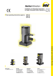
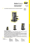
Oct. 2010
Assembly and Operating Instructions
for Netter Pneumatic External Vibrators BA No. 879E
Page 1/16
Series NVG, NVR, NVT
These operating instructions apply to:
Series NVG
Series NVR
Series NVT
Important note:
Before use of the pneumatic linear vibrators series NVG, NVR and NVT read this
operating instruction carefully and store afterwards.
Netter GmbH does not assume liability for damage to property and persons if the
product has been technically modified or if the notes and regulations of these
operating instructions have not been observed.
This documentation is copyrighted. All rights, e.g. for translation into other languages,
reprinting and copying of these operating instructions or parts hereof remain strictly
reserved.
Table of Contents
1 GENERAL NOTES
3 2 TECHNICAL DATA
4 3 DESIGN AND FUNCTION
6 4 SAFETY
7 5 TRANSPORT AND STORAGE
8 6 INSTALLATION
9 7 START-UP / OPERATION
12 8 SERVICE / MAINTENANCE
13 9 TROUBLESHOOTING
14 10 SPARE PARTS
15 11 APPENDIX
11.1 Accessories
11.2 Disposal
11.3 Enclosures
16 16 16 16 Scope of delivery:
Check the packaging for possible signs of transport damage. In the event
of damage to the packaging, check that the contents are complete and
undamaged. If there is any damage, inform the shipping agent. Compare
the scope of the delivery with the delivery note.
2
1
General notes
Pneumatic external vibrators of series
NVG, NVR and NVT comply with the
EC-machine regulation 2006/42/EG. In
particular, standards DIN EN ISO 12100
part 1 and 2 have been observed.
The vibrators generate non directed
vibrations.
General areas of application are:
Loosening,
conveying,
sorting,
compacting, and separating of bulk
materials and reduction of friction.
The drive medium is clean (filtered)
compressed air or nitrogen.
In addition, the frequency can be
infinitely controlled by means of
pressure regulators or throttles in the
supply line.
Special Features:
• No bearings
• Frequency infinitely variable by
air pressure
• Easily and quickly removable
• Noise reduced design NQT
NVG, NVR and NVT - vibrators are
used for the compaction of concrete, to
empty bunkers, to drive conveyor
troughs, sieves and vibrating tables.
In these operating instructions the following information and danger symbols are used.
Notes on important processes
Warning of a danger source
Important note on processes to
be especially observed
Environmental waste disposal
Ear protectors are required
2
Technical data
Drive medium:
Clean (filter ≤ 50 µm) compressed and lubricated air or nitrogen
Unfiltered air will cause damage to the vibrators.
Operating pressure:
2 bar to 6 bar*
Operating pressures must not be exceeded or fallen short of.
Temperature:
-10°C to 60°C*
Operating temperatures must not be exceeded or fall short of.
For higher temperatures appropriate vanes are available.
Frequency:
Max. 15.000 min-1
The maximum speed must not be exceeded.*
*) Higher temperatures and frequencies are only permitted after consultation by application engineers of Netter
GmbH.
Type
kçãáå~ä=
ÑêÉèìÉåÅó=
`ÉåíêáÑìÖ~ä=ÑçêÅÉ=
råÄ~ä~åÅÉ=
^áê=Åçåëìãéíáçå=
tÉáÖÜí==
ïáíÜçìí=ÜçëÉ=
xãáåJNz=
xkz
xÅãâÖz=
xäLãáåz=
xâÖz==c=
xâÖz==d=
Type
kçãáå~ä=
ÑêÉèìÉåÅó=
`ÉåíêáÑìÖ~ä=ÑçêÅÉ=
råÄ~ä~åÅÉ=
^áê=Åçåëìãéíáçå=
tÉáÖÜí==
ïáíÜçìí=ÜçëÉ=
tÉáÖÜí=
ïáíÜ=ÜçëÉ=
xãáåJNz=
xkz
xÅãâÖz=
xäLãáåz=
xâÖz==c=
xâÖz==d=
xâÖz=
QV=
kso=cI=ksd=d
RR
ksqcI=ksdd=
UO=
NNP
SN
NTKMMM=
NSKRMM=
NSKMMM=
VKMMM=
UKRMM=
TKNPM=
MIQR=
NKMMM=
SIS=
TIN=
NNKMMM=
MITQ=
NKNMM=
TIM
TIP
NQKORM=
NIMO=
NKOMM=
TIS
TIU
NRKPOM=
PIQR=
NKSMM=
NQIV=
NVIT=
PUKUPM=
VIUM=
NKTMM=
NSIV
OOIS
UQ=
ksqcI=ksdd
UT
NMR
VP=
NMU
NSKMMM=
NRKOMM=
NQKRMM=
NMKMMM=
NMKMMM=
OTKQMM=
NIVR=
NKSMM=
NQIM=
OMIM=
PTKRMM=
OIVS=
NSMM=
NQIQ
OMIQ
SOKOSM=
RIQM=
NKUMM=
NSIP
OOIQ
NUKQUM=
PIPT=
NKQRM=
J=
J=
OQKTUU=
QIRO=
NKRRM=
J=
J=
J=
J=
J=
NUIS=
OMIP=
NQT
ksd=ïáíÜ=Ä~ëÉ=éä~íÉK=ksq=~åÇ=knq=ïáíÜ=Å~êêáÉê=Ü~åÇäÉ=çå=íçéI=Ñçê=Äê~ÅâÉí=kse=QK=kso=ïáíÜçìí=Å~êêáÉê=Ü~åÇäÉI=Ñçê=Äê~ÅâÉí=kse=NK==
a~í~=çÄí~áåÉÇ=çå=S=Ä~ê
4
Sound level:
During the operation the sound level of the vibrators exceeds 85 dB(A),
ear protectors are required.
Due to their high power, the external vibrators NVG, NVT and NVR have
a sound level higher than 85 dB (A), especially if they are mounted on
plates, molds, etc.
A sound insulation of the unit is only useful if plates and formwork panels
are also insulated.
Pressure reduction reduces the sound level, but also the power.
Operating time:
The technical performance changes with long operating times (wear).
Dimensions [mm]
Vibrators:
NVG
NVR / NVT / NQT
Type
NVG 49, 55, 61
NVR 49, 55, 61
NVT 82, 113, 84, 87, 105
NVG 82, 113, 84, 87, 105
NQT 93, 108
A
220
182
240
260
240
B
111
140
185
187
230
C
175
175
150
145
240
Bracket:
5
D
60
90
83
140
80
E
180
225
200
-
F
70
-
∅G
20
17
-
H
20
12
-
3
Design and function
The vibration is produced by the
eccentric to the shaft driven internal
rotor, and (for larger units) by the
external rotor.
The compressed air enters at P into the
shaft and pushes the movable vane
against the inner rotor.
Through the air channels of the vane
the compressed air moves to the
pressure side (air chamber F) of the
vane.
The constant air increases the volume
of the air chamber F and displaces the
position of the rotor.
The rotation of the inner rotor changes
the shape of the chamber F to finally
connect the air with chamber G and the
compressed air escapes through the
exhaust holes R.
The rotor turns now with the help of
the kinetic energy until it reaches the
starting position and the two air
chambers, F and G are again incurred.
For larger units an additional external
rotor is driven by the inner rotor.
The position of the exhaust holes is observed during installation.
In this position, the vibrator starts
properly, the vane is free.
The exhaust air holes are in position
below right.
In this position, the vibrator do not start,
the inner rotor is lying on the vane.
The exhaust air holes are in position
above left.
6
4
Safety
NVG, NVR and NVT vibrators work
with compressed air.
Make sure the compressed air
supply is switched off during
installation.
Disconnect the supply lines (quick
coupling) before starting other work
on vibrators and supply lines.
Before starting operation all hoses
must be tightly connected.
A pressurized hose coming loose
can cause severe injury.
Vibrators as well as parts of the
structure may come loose because
of vibration. Falling parts can cause
damage to persons and material.
Screw retention components and/or
Loctite or similar must be used.
Screw connections must be checked
and, if necessary, retightened after 1
hour of operation and then at regular
intervals (normally each month).
In critical installation situations, the
unit must be secured with a steel
rope.
Sound level:
During the operation the sound
level of the vibrators exceeds 85
dB(A), ear protectors are required.
Due to their high power, the
external vibrators NVG, NVT and
NVR have a sound level higher
than 85 dB (A), especially if they
are mounted on plates, molds, etc.
A sound insulation of the unit is
only useful if plates and formwork
panels are also insulated.
Pressure reduction reduces the
sound level, but also the power.
7
Technical changes to the equipment may affect the characteristics
of the vibrators or even damage the units and cause the rejection of
any warranty claims.
Failures to comply with the operating instructions cause the
rejection of any warranty claims.
Drive medium:
Clean (filter ≤ 50 µm) compressed and lubricated air or nitrogen
Unfiltered air will cause damage to the vibrators.
Operating pressure:
2 bar to 6 bar*
Operating pressures must not be exceeded or fallen short of.
Temperature:
-10°C to 60°C*
Operating temperatures must not be exceeded or fall short of.
For higher temperatures appropriate vanes are available.
Frequency:
Max. 15.000 min-1
The maximum speed must not be exceeded.*
*) Higher temperatures and frequencies are only permitted after consultation by application engineers of Netter
GmbH.
5
Transport and storage
Check the packing for possible shipping damage.
If the packing is damaged, check the contents for completeness and
possible damage. In case of damage inform the transport agent. Compare
the scope of supply with the delivery note.
Special transport conditions are not
specified.
The units are packed ready for
installation. The type plate is mounted
on the vibrator.
The units are delivered with a socket, if
the socket is not already part of the
shaft.
If the units are ordered with 1 m hose,
coupling and cock valve, this standard
equipment
is
supplied
ready
assembled, if not specified differently.
The units should be stored in a dry and
clean environment.
Units must be oiled before being
returned to the stores (put machine oil
in air inlet and outlet and operate the
vibrator short).
The storage temperature may be between
-40°C and +60 °C.
(This does not apply for operating temperature,
compare with chapter 4 SAFETY, “Permissible
Operating Conditions”).
8
6
Installation
During installation please comply
strictly with the safety regulations in
chapter 4 and the accident
prevention instructions!
Make sure the compressed air
supply is switched off during
installation or when working on
vibrator and air supply lines.
Mounting the vibrator:
The vibrators of series NVG are
screwed with the base plate to the
vibrating mass. Depending on the
housing size the NVG is available with
a base plate with 2 bores (ø16,5 mm)
or 4 bores (ø17,0 mm). These base
plates are fastened accordingly with 2
or 4 screws M16, quality 8.8.
The vibrators of the series NVR or NVT
are to be fastened to the vibrating
mass by means of a separate bracket
(NVH-1 or NVH-4).
These brackets must be welded to the
construction to be vibrated.
In critical installation situations the unit must be secured with clamp and
steel rope.
Installation examples for NVG and NVT:
on vibration tables for
compaction, testing and others
(here NVG)
on hoppers for
emptying, on vibration
chutes (here NVT)
The shape of the housing has only a
minor influence on the effect. With the
units NVT, which are clamped with a
spigot nut in the welded on bracket
on tilting tables, etc. for
concrete compaction
(here NVT)
NVH-1 or NVH-4, the vibration
transmission is due to the particularly
strong connection especially favorable.
Start
The vibrators have to be mounted with
the air holes in positions A or B.
In positions C or D the vibrator will not
start, because the rotor is resting on
the vane, which is described in "Design
and Function," shown in the lower
figure. If required, the cover must be
rotated. This procedure is described
under "exchange of the vane".
Best start-up
in Pos. A + B
9
No start-up
in Pos. C + D
Mounting notes
The types NVG have a base plate which
is bolted to the vibrating structure.
The types NVR and NVT have a cast
housing which is clamped in a bracket
NVH -1 or NVH-4 by a spigot nut.
This brackets in weldable cast steel get
to be welded to the vibrating structure.
This combination vibrator / construction
is particularly force-fit.
Vibrators with the housing design NVR
and NVT are quickly removable.
Then for each position a bracket is
required.
Bracket NVH-1 or NVH or 4
for NVR or NVT
As a protection against loosening use self-locking screws and nuts, selflocking lock washers (no spring washer) or use a liquid screw retention
agent, e.g. Loctite 270.
The tightening torques can be taken
from the following table. Higher
tightening torques may cause
fracture of screws or tearing of
threads.
Inadequate screw connections may
cause loosening of units by vibration.
This can cause damage to persons
and material!
Recommended average tightening torques for screws property class 8.8 used on
NVG-vibrators (screws as delivered, not additionally greased or oiled):
Type
Thread*
Tightening torque
All types NVG
M 16
215 Nm
Housing screws
M 8
25 Nm
M 10
51 Nm
The screws M16 for NVG (version with base plate) can be secured with
LOCTITE or similar.
Tighten the spigot nut of the bracket NVH-1 with 150 Nm,
tighten the spigot nut of the bracket NVH-4 with 300 Nm and check
periodically, see Chap. 9 “Troubleshooting (Power drop)“.
Air supply line:
The air resistance increases with the
hose
length.
The
following
recommendations refer to hose lengths
of max. 5 m up to the next bigger hose
cross section (up to NVG/NVR 61 a
length of 10 m is possible). For longer
supply lines we recommend bigger
cross sections.
If the vibrators are supplied with a 1 m
hose, coupling and control cock valve,
the specification "5 m" (or 10 m) to the
supplied coupling is valid.
Minimum cross-sections for valves and hoses:
Valve: Connection G1/2, NW 12
Hoses: Inner diameter 16 mm
Check whether all hoses, valves and fittings are approved for the
operating pressure. When being used under higher temperatures, the
permissible pressure may be lower.
Before applying any pressure check that all pressure connections are
secure (hose clamps tightened?).
When using compressed air as drive
medium, it must be clean (filtered).
Unfiltered air leads to excessive
wear and complete damage of the
vibrator.
The compressed air supply must be
reliably fastened.
Filter recommended
Checklist for installation:
1) Install the unit. Lock the fastening screws.
2) Attend the expected operating temperature
3) Assemble maintenance unit, valve, supply line.
Have fastening screws been locked? Check!
4) Specification on hose length and diameter observed
5) Has the unit been secured against falling down?
11
7
Start-up / Operation
Start-up of the vibrators can be
performed immediately after the correct
installation.
The frequency can be adjusted or
regulated with the pressure regulator
on the service unit.
Sound level:
During the operation the sound level of the vibrators exceeds 85 dB(A),
ear protectors are required.
Due to their high power, the external vibrators NVG, NVT and NVR have
a sound level higher than 85 dB (A), especially if they are mounted on
plates, molds, etc.
A sound insulation of the unit is only useful if plates and formwork panels
are also insulated.
Pressure reduction reduces the sound level, but also the power.
Standard installation
Special plans on request
If the supply line is fitted with a 2/2way cock valve, this can be used to
regulate the frequency and the
centrifugal force. A pressure regulator
allows a more exact regulation
(independent
from
the
original
pressure). Valve, filter and lubricator
(regulator) may also be used for
several units. The size of these
components must then be determined
accordingly.
Start-up
The vibrators have to be mounted with
the air holes in position A or B.
In position C or D the vibrator will not
start, because the rotor is resting on
the vane, which is shown in "Design
and Function," in the lower figure.
If necessary, the housing must be
rotated. If this is not possible (e.g. in
case of NVT housings in conjunction
with the bracket NVH), the cover can
be rotated. This procedure is described
under "Exchange of the vane", see
page 15.
12
Best start-up
No start-up
in Pos. A + B
in Pos. C + D
The use of lubricated air significantly
increases the lifetime. If not lubricated
compressed air is used, give
periodically (e.g. every 1-2 hours)
1 cm3 oil in the supply line. Longer
intervals are possible, but can cause
rapid wear.
Recommended oil quality: SAE 10
ATTENTION:
Adjust number of drops while unit is running.
Only after the adjustment and correct function of the mist lubricator
the unit is ready for operation.
Checklist for commissioning:
1)
Check all hose connections before opening the compressed air
supply.
2)
Ensure the use of ear protection.
3)
Adjust the desired frequency on the pressure regulator.
4)
Adjust the mist lubricator, if existing.
The fastening screws for vibrator and vibrating mass must be retightened
or checked after 1 operating hour.
8
Service / Maintenance
When servicing the unit please observe the safety regulations in
chapter 4.
Retightening:
Screw connections must be checked and, if necessary, retightened after 1
hour of operation (after initial start-up) and then at regular intervals
(normally each month). The specified torque must thereby be observed
(see chapter 6).
Before each inspection and service
works shut off the compressed air
supply and secure it against
unintended activation!
Water must not enter into the inside.
Mist lubricator:
With a mist lubricator connected in
series make sure that it works as
specified (contents diminishing? number
of drops/min?). Top up oil.
Contamination:
Further notes can be found in chapter 9
„Troubleshooting“.
The maintenance intervals mainly
depend on the purity of the drive
medium.
Cleaning:
All NVT vibrators can be externally
cleaned with pressure water, as long as
the exhaust openings are closed.
13
9
Troubleshooting
Fault
No start
Too low
power
Possible cause
Air supply
Wrong position of
exhaust bores, see
"Installation"
Vane jammed,
missing or incorrectly
inserted.
Hose cross-sections
Remedy
Check the pressure at the unit! Sufficient
pressure? Check the valve.
Turn vibrator or cover, see below "Exchange of
vane".
Check the vane, see below "Exchange of vane".
Observe minimum cross-sections and lengths,
see specifications under
"Installation". Check
the air pressure. Check the supply lines.
Wear
Check the vane in particular, also cover and inner
rotor.
Unit runs in resonance Better reinforcement. Or choose a unit with a
frequency. No
lower working moment (smaller outer rotor).
increase in speed
despite an increase of
pressure.
Power drop Screws loose (typical: Re-tighten the screws, especially the nuts on
sudden speed
NVH-brackets.
reduction)
Unit soiled
Fill approx. 1 cm3 of kerosene into the supply line
and run the vibrator for a moment.
Sound level Frequency range,
Avoid locations which may rattle. Adjust the
rattling
frequency to a lower sound pressure level.
14
Exchange of the Vane
The vane is an item which wears out.
The use of clean and lubricated compressed air prolongs its lifetime.
In case of a power drop the reason is
normally a worn vane - if the above
tests do not reveal anything else. The
vane must be replaced as follows:
1
2
3
4
5
6
7
8
9
10
11
12
Loosen the housing screws 10, 11, 12
and press the axle 6 out from the side of
the front flange 2. This may be accomplished either hydraulically (raise the
rim of the housing for this purpose) or by
clamping the recess A of the housing in a
vice and knocking the shaft 6 with a
hammer and a brass mandrel. The shaft
will then drop out of the housing together
with the rear flange 3 and the fitting 9.
These parts remain together. The rotor or
the rotors 4, 5 will also fall out.
ground in so that it fits tightly. The
open channels of the vane must point
away from the exhaust bores B.
Assembly must be performed in
reverse order, whereby the cover is
pressed in or knocked in with a plastic
hammer. During this procedure
observe the correct position of the
flanges to each other (fitting keys 8!).
If necessary (start-up position) the
flanges may be turned. In this case
the front flange 2 must also be
loosened. The housing screws 10
must all be re-tightened after a short
test operation.
Now inspect the vane for signs of wear
and replace it with a new one, if this is
necessary. The vane must be easy to
move, or otherwise it must be
Tightening torque for housing screws:
10
Housing
Front flange
Rear flange
Outer rotor
Inner rotor
Shaft
Vane
Fitting key
Connecting fitting
Housing screw
Stop nut
Lock washer
M 8 = 25 Nm
M 10 = 51 Nm
Spare Parts
Please provide the following information when ordering spare parts:
1. Type of unit
2. Description of spare part
3. Required quantity
15
11
Appendix
11.1 Accessories
The following accessories are available for the vibrators (on request):
Description
Remark
Hose material and
fittings
for air supply and exhaust (option), in different
qualities and dimensions
3/2- or 2/2-way valves
for electric, pneumatic and manual control
Throttle valves
for frequency control, manually adjustable or pneumatically controllable (for remote control). See also FL-R units (pressure regulators).
F-L-R units
Filter, pressure regulator, lubricator or complete units
respectively.
Duty and break cycle
control
electric or pneumatic, for interval operation
Brackets
for quick relocation of vibrators on formwork, containers etc.
Special versions:
With exhaust air discharge, e.g. for the use in aggressive environments, rotors for other working moments.
11.2 Disposal
Depending on the material, the parts must be disposed of according to official
regulations.
Material specifications:
All parts of these vibrators are suitable for recycling
• Housing:
⇒
steel or cast steel
• Rotor, Shaft, Cover:
⇒
hardened steel
• Bracket NVH:
⇒
weldable cast steel or steel
All units can be disposed of through Netter GmbH.
The current disposal prices are available on request.
11.3 Enclosures
Enclosure(s):
Declaration of incorporation
Further information available
request: Leaflet no. 14 (Vibrators),
16
on