1
Multi-Axis Controllers and Drives
High Performance Computing and Control
SEC-AC-SMLC Multi-Axis Controllers
Integrated PLC functionality and OPC server
Control up to 16 axes
Ethernet connectivity and optional Profibus® master variant
IEC 61131-3 applications programming
PLCopen and enhanced motion function blocks
SEC-SDD ServoWire® Digital Drives
IEEE 1394 ServoWire® drive network
Simplified servo system tuning
115 VAC single phase and 230 VAC single/three phase
Supports both resolver and incremental encoder feedback
Position loop update rates up to 2 kHz
Applications
Circular, linear and helical interpolation
Reciprocating flying shear
Electronic gearing, cams and profiling, registration control
Rotary knife cut-off and cut to length
Coordinated multi-axis control
Info 140 US
System Overview
Multi-Axis Controllers and Drives
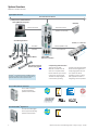
Typical System Overview
Plant Floor Ethernet Network
Development PC/SCADA Software
Festo VipWIN/OPC EasyClient
HMI (FED)
Ethernet and Serial
Ethernet and Serial
(Modbus TCP and RTU)
ServoWire Digital Drives
Remote I/O – Festo CPX
ServoWire
Ethernet (Modbus TCP)
(FireWire)
and Profibus DP
Festo Motors
Festo Electromechanical
Actuators (see page 42)
ServoWire® is a registered trademark of ORMEC Systems
Corporation. All other product names are trademarks or
registered trademarks of their respective holders.
SEC-AC-SMLC
Multi-Axis Controllers
Complete Integrated Automation
The Festo SEC-AC-SMLC
Multi-Axis Controller is at the
center of a complete solution
that can meet all of your motion
control, logic, and I/O needs.
The SMLC is a fully-integrated
control solution, providing
hardware and software building
blocks that are engineered to
easily plug together and work
as a system. This allows
engineers to focus on solving
their application instead of
integrating control components.
SEC-AC-SMLC Multi-Axis Controllers
SEC-AC-SMLC Controllers
support the following
platforms and standards.
SEC-SDD ServoWire® Digital Drives
SEC-SDD ServoWire Digital
Drives support the following
platforms and standards.
2
Multi-Axis Controllers and ServoWire® Digital Drives – Subject to change – 12/2006
Contents
Multi-Axis Controllers and Drives
Introduction
Product Overview ...................................... 4
Features and Benefits ................................ 6
Online Literature
Literature in PDF format is available for
download at www.festo.com/us/m&c/smlc.
1
Page
4
SEC-AC-SMLC Multi-Axis Controllers
Technical Data
Electrical .................................................... 8
Dimensions .............................................. 10
Programming Software
2
CoDeSys Development Software .............. 12
Ordering Data
Page
7
Multi-Axis Controllers .............................. 14
SEC-SDD ServoWire® Digital Drives
Technical Data
Electrical .................................................. 16
Dimensions .............................................. 19
Drive Configuration Software
3
ServoWire Pro Software ............................ 23
Ordering Data
Page
15
ServoWire Digital Drives .......................... 26
Engineering Support
Function Blocks ........................................ 30
Motor and I/O Compatibility .................... 33
4
Festo Servo Motor Performance Data ...... 34
System Selection ...................................... 36
Page
29
Sensor Selection ...................................... 38
Regen Resistor/Drive Compatibility
and Line Filter Selection and Sizing .......... 39
Glossary .................................................... 40
12/2006 – Subject to change – Multi-Axis Controllers and ServoWire® Digital Drives
3
Product Overview
SEC-AC-SMLC Multi-Axis Controllers and SEC-SDD ServoWire® Digital Drives
A Complete Motion Control Solution
1
Control of up to 16 Axes
The SEC-AC-SMLC with the
ServoWire® Drive Network and
Modbus TCP communications
provide state-of-the-art I/O and
motion control, all programmed
using the CoDeSys IEC 61131-3
standard languages, controlling
up to a maximum of 16 axes.
4
High Performance Computing
The SEC-AC-SMLC Controller
features high performance
computing capability combined
with a true real-time operating
system (RTOS). Using the
industry standard family of
Intel 32-bit processors to run
the QNX RTOS provides plenty
of cost-effective, robust
computing power for even the
most demanding multi-axis
motion and I/O control
applications.
Flexible Machine and Integrated
Drive I/O Capabilities
The SEC-AC-SMLC provides a
flexible approach to meeting
machine I/O requirements.
It offers a unique ability to
interface with high-speed drive
based I/O. General purpose I/O
options are fully supported using
Modbus TCP (to Festo CPX-FEC).
A wide variety of analog and
digital I/O modules as well as
valves can be cost-effectively
connected to and controlled by
the SEC-AC-SMLC. Variants with
integrated Profibus® master (for
up to 16 axes) are also available.
ServoWire® Drive Network
Festo AC brushless servo motors
(MTR-AC) and ServoWire digital
servo drives (SEC-SDD) offer
tested and guaranteed
performance with the
SEC-AC-SMLC. Full digital
control offers compelling
benefits – eliminating manual
drive setup and providing
real-time software access to all
parameters. In a SEC-AC-SMLC
system, the position, velocity
and torque loops are all closed
by the digital signal processors
(DSPs) in the ServoWire Drives,
based on commands sent from
the SEC-AC-SMLC controller.
Multi-Axis Controllers and ServoWire® Digital Drives – Subject to change – 12/2006
Product Overview
SEC-AC-SMLC Multi-Axis Controllers and SEC-SDD ServoWire® Digital Drives
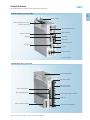
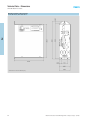
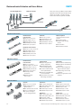
Multi-Axis Controller, Type SEC-AC-SMLC
1
Power connector
Profibus Master Sub-D connector
(Profibus variants only)
IEEE 1394 FireWire ports
Status indicators
Keyboard connector
Digital I/O
USB ports*
System card
Ethernet (RJ45) ports
Analog I/O
VGA port
RS232 serial ports
* Currently not supported
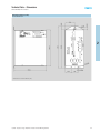
ServoWire Digital Drive, Type SEC-SDD
Drive ID setting switch
Bus power indicator
Main control power
and motor connector
Drive ID status indicator
IEEE 1394 FireWire ports
External regen register connection
Digital I/O
Resolver feedback module
12/2006 – Subject to change – Multi-Axis Controllers and ServoWire® Digital Drives
Incremental encoder feedback
5
Features and Benefits
SEC-AC-SMLC Multi-Axis Controllers and SEC-SDD ServoWire® Digital Drives
Integration
1
The SEC-AC-SMLC multi-axis
controller and CoDeSys
development software
combine to provide flexible
and effective networking
solutions for interfacing
machine I/O, HMIs and
factory data networks.
The controller seamlessly
integrates with HMI devices
using Modbus RTU and
Modbus TCP communications.
Computing Power
Using Intel 32-bit processors
provides powerful computing
capabilities for the most
demanding multi-axis motion
and I/O control applications.
QNX Real Time Operating
System (RTOS) provides
real time reliability and
robust performance.
The controller also lets users
utilize Windows based HMIs
such as Wonderware InTouch,
Rockwell Automation RS View,
Intellution iFIX, CiTect or GE
Cimplicity to communicate
with the SMLC via OPC Server.
The variables in the SMLC
can be interfaced to these
software programs using
Ethernet or Serial
communications. OPC
provides open, interoperable
connectivity for automation
and the enterprise systems
used in industrial applications.
Standardization
Uses open standard
communications technologies
– Ethernet (TCP/IP)
– Modbus TCP
– Profibus DP
– OPC Server
– Drive network based
on IEEE 1394 FireWire
All provide flexible interfaces
for connecting to general
purpose I/O, HMIs and factory
data networks.
The SEC-AC-SMLC Multi-axis
controllers and SEC-SDD
ServoWire digital drives are
CE compliant and UL certified.
Interoperability is assured
by the creation and the
maintenance of open
standards and specifications,
by an independent
organization that includes
both users and manufacturers
of industrial automation
equipment. The CoDeSys
OPC server is included with
CoDeSys at no additional
charge and includes tools for
assigning the SMLC name and
IP address, selecting the group
of variables to be accessible
through the server, refreshing
properties, etc.
The SMLC multi-axis controller
provides two Ethernet ports
(TCP/IP). CoDeSys includes
all the software necessary for
communications via Ethernet
TCP/IP, enabling easy access
to the SMLC from any system
connected to the network.
This capability allows users
to easily implement remote
debug and diagnostic
capabilities without the
need to purchase additional
software.
Flexibility
Developing motion and I/O
programming with a standard
set of software tools provided
by CoDeSys IEC61131-3
development software and
PLCopen motion function
blocks (together with ORMEC
enhanced motion library)
streamlines software
development and creates
application programs that are
more effective and easier to
support in the field.
Pre-programmed function
blocks allow for CPX-FEC
communications over
Modbus TCP.
Reusable function blocks
reduce engineering/
programming time, thereby
reducing system development
costs.
6
Multi-Axis Controllers and ServoWire® Digital Drives – Subject to change – 12/2006
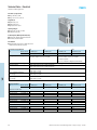
SEC-AC-SMLC Multi-Axis Controllers
2
SEC-AC-SMLC Controllers
Three models available
with two variants each
– 3-Axis
– 8-Axis
– 16-Axis
An integrated Profibus
master variant is available
for all three controller models
12/2006 – Subject to change – Multi-Axis Controllers and ServoWire® Digital Drives
7
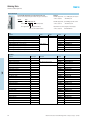
Technical Data – Electrical
SEC-AC-SMLC Multi-Axis Controllers
Integrated Features
PLC functionality
OPC Server
Digital and Analog inputs and outputs
Three RS232 serial ports (four on the M16 model)
Drive Network
High bandwidth synchronous, all digital servo
drive network based on IEEE 1394 (2 ports)
2
Networking
Two Ethernet 10/100 base T, RJ45 ports
supporting Ethernet TCP/IP for connection to
factory data networks. Modbus TCP for
connecting up to 16 CPX-FEC valve terminals
and HMI devices.
Controller Specifications
Type
yp
3-Axis
SEC-AC-SMLC-M3-SA
SEC-AC-SMLC-M3-PB-SA
8-Axis
SEC-AC-SMLC-M8-SA
SEC-AC-SMLC-M8-PB-SA
16-Axis
SEC-AC-SMLC-M16-SA
SEC-AC-SMLC-M16-PB-SA
CPU Processor
Total controller memory
SMLC program memory / system card
Non-volatile variable memory
Input AC Power Ratings
SEC-AC-SMLC controller
650 MHz Celeron
128 MB DRAM
128 MB removable compact flash
32 KB battery backed SRAM
933 MHz Pentium III
1.4 GHz Pentium M
Battery Power
Main processor – BIOS
Battery backed SRAM
Data retention
Digital I/O Power Requirements
VIO+
VIODigital Inputs; 8
Current (switch on)
Common VIO+
Voltage (max)
Digital Outputs; 8
Maximum sink current
Low level voltage
High level voltage
Voltage (max)
Analog Input, 1 Channel
Input range
Analog Output, 1 Channel
Output range
Update rate
Output settling time
Output current (max)
I/O Connection
Digital I/O
Analog I/O
8
115 VAC (90 to 127 VAC); 47 to 63 Hz
230 VAC (190 to 253 VAC); 47 to 63 Hz
One lithium battery
One BR2032 lithium battery (3 volt, 190 mAh)
10 years of data retention, powered. 1 year minimum, 5 year typical, unpowered.
VDC
4.5 to 27
Not internally tied to SMLC ground (externally tie to ground)
mA (min)
mA (max)
VDC
0.7
7.0
Inputs sink to VIOVIO+ + 5
mA
VDC
VDC
VDC
33
1.2
VIO+ -0.5
27
VDC
+10 to -10
VDC
+10 to -10
Once per scan
20
10
µs
mA
Sub-D 25-pin female
6-pin clamp connector
Multi-Axis Controllers and ServoWire® Digital Drives – Subject to change – 12/2006
Technical Data – Electrical
SEC-AC-SMLC Multi-Axis Controllers
Serial Interface Specifications
Development Port COM1
Connector
Standards
Default configuration
9-pin male Sub-D
EIA RS-232C
8 data bits
1 stop bit
no parity
9600, 4800, 2400, 1200 Baud; 115.2 kB, 57.6 kB, 38.4 kB, 19.2 kB (Default)
Baud rate
HMI Serial Port COM2
Connector
Standards
Default configuration
9-pin Male Sub-D
EIA RS-232C
8 data bits
1 stop bit
no parity
9600, 4800, 2400, 1200 Baud; 115.2 kB, 57.6 kB, 38.4 kB, 19.2 kB (Default)
Baud rate
Serial Ports COM3 and COM41)
Connector
Standards
Default configuration
2
9-pin Male Sub-D
EIA RS-232C
8 data bits
1 stop bit
no parity
9600, 4800, 2400, 1200 Baud; 115.2 kB, 57.6 kB, 38.4 kB, 19.2 kB (Default)
Baud rate
1) COM4 is only available with model M16.
Certification
c UL us - Listed
89/336/EEC (EMC)
73/23/ECC (low voltage)
Profibus DP Specifications
For SEC-AC-SMLC-M...-PB-SA Versions Only
Bus connection
Fieldbus baud rates
Sub-D 9-pin female
Up to 12 MB
Operating and Environmental Conditions
All Models
Operating temperature
Storage temperature
Relative humidity
Mounting and airflow
0 to 50 °C / 32 to 122 °F
-25 to 70 °C / -13 to 158 °F
10% to 95% at 40 °C, non condensing
Mounting must be in the vertical position, airflow must be unrestricted
Weights
Type
yp
3-Axis
SEC-AC-SMLC-M3-SA
SEC-AC-SMLC-M3-PB-SA
Weight
kg
1.49
12/2006 – Subject to change – Multi-Axis Controllers and ServoWire® Digital Drives
8-Axis
SEC-AC-SMLC-M8-SA
SEC-AC-SMLC-M8-PB-SA
16-Axis
SEC-AC-SMLC-M16-SA
SEC-AC-SMLC-M16-PB-SA
1.58
9
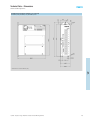
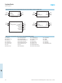
Technical Data – Dimensions
SEC-AC-SMLC Multi-Axis Controllers
Multi-Axis Controllers (3-Axis and 8-Axis)
SEC-AC-SMLC-M3-SA, SEC-AC-SMLC-M8-SA
2
All dimensions are shown in millimeters [mm]
10
Multi-Axis Controllers and ServoWire® Digital Drives – Subject to change – 12/2006
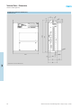
Technical Data – Dimensions
SEC-AC-SMLC Multi-Axis Controllers
Multi-Axis Controllers (16-Axis)
SEC-AC-SMLC-M16-SA
2
All dimensions are shown in millimeters [mm]
12/2006 – Subject to change – Multi-Axis Controllers and ServoWire® Digital Drives
11
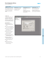
Programming Software
SEC-AC-SMLC Multi-Axis Controllers
CoDeSys Development Software
Developing Motion control and I/O
programming using a standard set of
software tools streamlines software
development and creates
application programs that
are more effective and easier
to support in the field.
The CoDeSys development software
utilizes standard IEC 61131-3
programming and PLCopen motion
function blocks to provide proven,
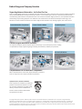
CoDeSys Development Tools
Program motion control and logic
using standard IEC61131-3 tools.
The suite of programming languages
and charting tool simplifies machine
development and support. Select
among graphical and text-based
languages – Relay Ladder Logic,
Function Block Diagram, Structured
Text, Instruction List, Sequential
Function Chart or Continuous Function
Chart. The CoDeSys development
environment provides tools for
creating visualizations which can
be used to build operator entry and
diagnostic displays useful for testing
and debugging the application.
PLCopen Motion Control Library
PLCopen (an independent worldwide
association) has defined a standard
library of motion programming
function blocks which cover all the
IEC 61131-3 programming languages.
Function blocks cover both motion
and administrative functions like
ReadParameter, ReadActualPosition,
PositionProfile, CamIn, CamOut.
ORMEC Motion Control Extensions
ORMEC's motion programming
implementation (ServoWire Motion
Blocks) conforms to the PLCopen
motion block definitions and provides
powerful, flexible functionality beyond
that defined in the standard. Using
the ServoWire Motion blocks, a variety
of applications can be written in any
of the IEC 61131-3 programming
languages. Function blocks cover both
motion and administrative functions
like blocks handling enhanced
diagnostic capabilities, Move Absolute
in Time, Move Relative at Velocity.
open standard tools for developing
application programs for motion
control and I/O control running on
a single controller.
2
12
Multi-Axis Controllers and ServoWire® Digital Drives – Subject to change – 12/2006
Programming Software
SEC-AC-SMLC Multi-Axis Controllers
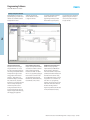
CoDeSys Development Software
The PLCopen standard Motion Control
Library, plus powerful ORMEC
extensions, bring new levels of motion
performance for electronic gearing,
camming, registration control and
coordinated, multi-axis applications.
2
Built-in Networking Support
Standard networking solutions
and support for Ethernet TCP/IP,
Modbus/TCP, Profibus DP and
OPC Server provide connectivity
to factory data networks,
supporting connectivity for motion
and I/O control and HMI devices
(which support Modbus TCP or
Modbus RTU).
Reduced Learning and
Engineering time
Reduce training costs by learning
one set of programming languages
used by multiple control vendors.
Provide flexibility for selecting the
best programming approach and
method for the specific application
tasks and requirements. In addition,
the programmer is able to develop
and deploy reusable function blocks
which can reduce future software
development costs.
PLCopen Function Block
Enhanced Function Block
MC_Camin
Execute
MasterScaling
SlaveScaling
CamTableID
RatioSpecified
StartRatioln
StartCondition
StartIndex
EndIndex
Tag
Master
Slave
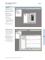
Highly Structured Programming
Application programs can be written
as a state machine in Sequential
Function Chart (SFC). SFC provides
a graphical flow charting tool that
illustrates the program flow and
structure of the user's application
program. SFC makes it easier to view
a multi-layered, graphical model of
the program and provides excellent
tools for application development
and maintenance.
InSync
CommandAborted
Error
ErrorID
StartRatioOut
12/2006 – Subject to change – Multi-Axis Controllers and ServoWire® Digital Drives
Auto_MoveAxis1
MC_MoveRelativeInTime
Execute
Distance
MoveTime
Acceleration
Deceleration
AccelDecelType
SCurve
StartCondition
StopCondition
StopDelay
StopBlind1
StopBlind2
Queue
Tag
Axis
Done
CommandAborted
Error
ErrorID
13
Ordering Data
SEC-AC-SMLC Multi-Axis Controllers
Order Code Example
Examples:
8-Axis controller without Profibus master
– Order: 13039604
SEC-AC-SMLC-M8-SA
Festo multi-axis controllers are ordered with an order code.
The order code consists of the part number and type as shown below.
Part No.
13040199
Type
SEC-AC-SMLC - M16 - PB - SA
Controller model
Maximum number of axes
2
3-Axis controller with Profibus master
– Order: 13040197
SEC-AC-SMLC-M3-PB-SA
Standard SA product
With Profibus master
Cable from controller to drive, bilingual (2 meter length)
– Order: 13039613
KSDD-CLR-SW2-SA
Controllers
Description
Axis Configuration
Voltage
Part No.
Type
SMLC Model M3
SMLC Model M8
SMLC Model M16
SMLC Model M3
SMLC Model M8
SMLC Model M16
3-axis
8-axis
16-axis
3-axis with Profibus Master
8-axis with Profibus Master
16-axis with Profibus Master
115/230
/
VAC
13039603
13039604
13039605
13040197
13040198
13040199
SEC-AC-SMLC-M3-SA
SEC-AC-SMLC-M8-SA
SEC-AC-SMLC-M16-SA
SEC-AC-SMLC-M3-PB-SA
SEC-AC-SMLC-M8-PB-SA
SEC-AC-SMLC-M16-PB-SA
Controller Cable
Description
Cable Length
Connection
Part No.
Type
ServoWire Cable, Bilingual
ServoWire Cable, Bilingual
1m
2m
Cable from controller to drive
13039612
13039613
KSDD-CLR-SW1-SA
KSDD-CLR-SW2-SA
Accessories
Description
Cable Length
Part No.
Type
Digital I/O Cable for SEC-AC-SMLC
Digital I/O Cable for SEC-AC-SMLC
Digital I/O Cable for SEC-AC-SMLC
Digital I/O Cable for SEC-AC-SMLC
Phoenix Extension Block (25 pin)
Flash Memory Card for SMLC Controller (128 MB)
Analog Connector for SEC-AC-SMLC
Power Connector for SEC-AC-SMLC
1m
3m
5m
X m (adder/meter)
–
–
–
–
13039971
13039972
13039973
13039974
13039975
13039976
13039977
13039994
KDIO-SMLC-1-SA
KDIO-SMLC-3-SA
KDIO-SMLC-5-SA
KDIO-SMLC-X-SA
KPHX-CON-SMLC-SA
MEM-SMLC-SA
AIO-CONN-SMLC-SA
PWR-CONN-SMLC-SA
Part No.
Type
13039641
13039937
13039938
P.SW-CDK-SA
P.BE-SEC-AC-SMLC/SDD-SA
P.BE-SEC-AC-SMLC-SA
Documentation and Software
Description
CoDeSys Software Development Kit, CDROM with 1 yr Maintenance/Support1)
CD Documentation – Controller, Drives and Motors (Installation and Commisioning Manuals)
SEC-AC-SMLC Controllers – Installation and Commisioning Manual
1)
CD-ROM includes ServoWire Pro (drive paramaterization software) and installation and commissioning manuals for SEC-AC-SMLC controllers and SEC-SDD drives.
Maintenance contract can be renewed at a nominal charge.
All SEC-AC-SMLC controllers are supplied with:
Analog I/O connector
Power Connector
Flash Memory
14
Documentation
Manuals in PDF format are
available for download at:
www.festo.com/us/m&c/smlc.
Multi-Axis Controllers and ServoWire® Digital Drives – Subject to change – 12/2006
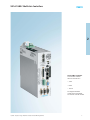
SEC-SDD ServoWire® Digital Drives
SEC-SDD ServoWire Drives
Four models available
with two variants each
– 2A drive with integrated
resolver feedback module
– 4A drive with integrated
resolver feedback module
– 8A drive with integrated
resolver feedback module
– 14A drive with integrated
resolver feedback module
Variant with encoder feedback
for all four models is available
12/2006 – Subject to change – Multi-Axis Controllers and ServoWire® Digital Drives
15
3
Technical Data – Electrical
SEC-SDD ServoWire® Digital Drives
Drive Power / Output Current:
Range: 290 W to 3.3 kW
Range: 2.5 A rms to 13.9 A rms
Integrated I/O:
Digital inputs (3+1)
Digital outputs (4+1)
High-speed sensor inputs
Operating Voltages:
Single-phase (115 VAC, 230 VAC)
Three-phase (230 VAC)
Feedback Options (With Open Wire Detection):
Resolver with software configurable resolution
Incremental encoder interface
Drive Network:
High bandwidth synchronous, all digital servo drive
network based on IEEE 1394 (2 ports)
General Electrical Specifications
2A
Type
Resolver Variant SEC-SDDR2/4-SA
Encoder Variant SEC-SDDE2/4-SA
Incoming main power line voltage
Incoming control power line voltage
Main DC bus vlotage
Shunt regulator activation DC bus voltage
3
High bus voltage fault activation
DC bus voltage
Low bus voltage fault activation
DC bus voltage
Output Specifications
Type
16
8A
SEC-SDDR8/14-SA
SEC-SDDE8/14-SA
14 A
SEC-SDDR14/24-SA
SEC-SDDE14/24-SA
Single phase, 50/60 Hz
115 (+15%, -20%) or 230 (+15%, -20%) VAC
Single phase, 50/60 Hz
115 (+15%, -20%) or 230 (+15%, -20%) VAC
Three phase, 50/60 Hz
230 (+15%, -20%) VAC 20 W typical (45 W maximum)
Single phase, 50/60 Hz; 115 (-20%) to 230 (+15%) VAC [auto adjusting]
115 VAC nominal input power: 163 VDC nominal level
230 VAC nominal input power: 325 VDC nominal level
115 VAC motors: 207 VDC
230 VAC motors: 395 VDC
115 VAC motors: 237 VDC
230 VAC motors: 425 VDC
115 VAC motors: 94 VDC
230 VAC motors: 205 VDC
2A
Resolver Variant SEC-SDDR2/4-SA
Encoder Variant SEC-SDDE2/4-SA
Single-phase 115 VAC Input
Rated output power
KVA
Continuous current
Amps RMS / ∅
Peak current, 2 sec.
Amps RMS / ∅
Single-phase 230VAC Input
Rated output power
KVA
Continuous current
Amps RMS / ∅
Peak current, 2 sec.
Amps RMS / ∅
Three-phase 230 VAC Input
Rated output power
KVA
Continuous current
Amps RMS / ∅
Peak current, 2 sec.
Amps RMS / ∅
4A
SEC-SDDR4/7-SA
SEC-SDDE4/7-SA
4A
SEC-SDDR4/7-SA
SEC-SDDE4/7-SA
8A
SEC-SDDR8/14-SA
SEC-SDDE8/14-SA
14 A
SEC-SDDR14/24-SA
SEC-SDDE14/24-SA
0.29
2.5
4.4
0.49
4.2
7.4
0.58
5.1
8.8
0.98
8.6
14.8
0.59
2.5
4.2
0.98
4.1
7.1
1.17
4.9
8.5
1.97
8.2
14.3
N/A
N/A
N/A
N/A
N/A
N/A
1.95
8.2
14.2
3.32
13.9
24.1
Multi-Axis Controllers and ServoWire® Digital Drives – Subject to change – 12/2006
Technical Data – Electrical
SEC-SDD ServoWire® Digital Drives
I/O Specifications
All Models
I/O Power Supply (V+S and V-S)
Externally supplied voltage
For high speed sensor inputs, digital inputs, and digital outputs
Max voltage between V+S and V-S
+27 VDC maximum
High-speed Sensor Inputs
Input current depends on software configuration
NPN type sensor
– 8.9 mA at 24 VDC (with 2.7 kΩ pull-up resistor selected in drive)
PNP type sensor
– Current depends on pull-down resistance in sensor (or external pull down)
Maximum voltage
V+S
Minimum acceptance time
1 µs
Turn on voltage
Receiver output:
V IN > 0.5 x (V+S) + 0.4 VDC
– high
– low
V IN < 0.5 x (V+S) + 0.1 VDC
Digital Inputs, 4 [1 Input: bidirectional1)], Optically Coupled
Current (switch on)
0.7 mA minimum
7.0 mA maximum
Voltage maximum
5V + V+S maximum
Digital Outputs, 5 [1 Output: bidirectional2)], Optically Coupled
Maximum sink current
33 mA
Low level voltage
0.7 VDC maximum (lc = 33 mA)
High level voltage
V+S –0.5 VDC
Absolute maximum
27 VDC
1) Sensor/switch should sink current to prevent an over travel limit condition (NPN or switch).
2) Bidirectional pin shared.
Certification
c UL us - Listed
89/336/EEC (EMC)
73/23/ECC (low voltage)
3
Performace Specifications
Type
PWM frequency
Torque loop
Position loop
Velocity loop
2A
Resolver Variant SEC-SDDR2/4-SA
Encoder Variant SEC-SDDE2/4-SA
4A
SEC-SDDR4/7-SA
SEC-SDDE4/7-SA
8A
SEC-SDDR8/14-SA
SEC-SDDE8/14-SA
20 kHz
10 kHz
500 Hz to 2 kHz
2.5 kHz
14 A
SEC-SDDR14/24-SA
SEC-SDDE14/24-SA
10 kHz
Weights
Type
2A
Resolver Variant SEC-SDDR2/4-SA
4A
SEC-SDDR4/7-SA
8A
SEC-SDDR8/14-SA
14 A
SEC-SDDR14/24-SA
Type
2.0 kg
Encoder Variant SEC-SDDE2/4-SA
1.9 kg
SEC-SDDE4/7-SA
SEC-SDDE8/14-SA
2.7 kg
SEC-SDDE14/24-SA
2.6 kg
12/2006 – Subject to change – Multi-Axis Controllers and ServoWire® Digital Drives
17
Technical Data – Electrical
SEC-SDD ServoWire® Digital Drives
Motor Feedback Specifications
Motor Encoder Interface
Channels A and B – Differential Digital Inputs
Common mode input
–15 VDC to +15 VDC maximum
Absolute maximum input voltage
± 25 VDC
Maximum encoder counts per rev
1,000,000 (after 4x decode)
Maximum encoder data rate
4 MHz
Quadrature specification
90°, ± 45°
Differential turn on voltage:
Receiver output:
VID > 0.7 V
–H
– Not defined
–0.7 V > VID > 0.7 V
–L
VID < –0.7 V
Channel Z (Index Pulse) – Differential and Single-ended Digital Input
Common mode input
–12 VDC to +12 VDC maximum
Absolute maximum input voltage
± 25 VDC
Differential turn on voltage
Receiver output:
VID > 0.2 V
–H
– Not defined
–0.2 V > VID > 0.2 V
–L
VID < –0.2 V
Single-ended turn on voltage
Receiver output:
VIS > 3 V
–H
– Not defined
2 V > VIS > 3 V
–L
VIS < 2 V
Encoder Power Supply
5.3 VDC, ± 5%; 450 mA maximum
Encoder Connection
25-pin female
Over-temperature Sensing – Optically Isolated Digital Input1)
Current to turn on
2.5 mA
Maximum voltage
+12 VDC maximum
Motor Feedback Specifications
Resolver Interface
3
Feedback resolution (software configurable)
65,536 cnt/rev @ 16-bit / 16,384 cnt/rev @ 14-bit / 4,096 cnt/rev @ 12-bit
Maximum motor speed
1,500 rpm @ 16-bit / 6,000 rpm @ 14-bit / 24,000 rpm @ 12-bit
Resolver type
Single speed
Transformation ratio
0.5
Excitation – Differential Digital Output
Excitation amplitude
0 to 8 V RMS / 4 V RMS at 100% (default) in ServoWire Pro
Excitation frequency
2.5, 5 to 10 kHz, software configurable
Feedback Signal (Sine/Cosine) – Differential Digital Inputs
Feedback amplitude
2 V RMS, ± 15%
Resolver Connection
25-pin male
Over-temperature Sensing – Optically Isolated Digital Input1)
Current to turn on
2.5 mA
Maximum Voltage
+12 VDC maximum
1) Should be normally sinking current to prevent an over-temperature condition.
Operating and Environmental Conditions
All Models
Operating temperature
Storage temperature
Operating and storage humidity
18
0 to 50 °C / 32 to 122 °F
–20 to 70 °C / –13 to 158 °F
10% to 90%, non condensing
Multi-Axis Controllers and ServoWire® Digital Drives – Subject to change – 12/2006
Technical Data – Dimensions
SEC-SDD ServoWire® Digital Drives
ServoWire Drives with Encoder Feedback (2 A, 4 A and 8 A)
SEC-SDDE-2/4-SA, SEC-SDDE-4/7-SA, SEC-SDDE-8/14-SA
All dimensions are shown in millimeters [mm]
3
12/2006 – Subject to change – Multi-Axis Controllers and ServoWire® Digital Drives
19
Technical Data – Dimensions
SEC-SDD ServoWire® Digital Drives
ServoWire Drives with Encoder Feedback (14 A)
SEC-SDDE-14/24-SA
All dimensions are shown in millimeters [mm]
3
20
Multi-Axis Controllers and ServoWire® Digital Drives – Subject to change – 12/2006
Technical Data – Dimensions
SEC-SDD ServoWire® Digital Drives
ServoWire Drives with Resolver Feedback (2 A, 4 A and 8 A)
SEC-SDDR-2/4-SA, SEC-SDDR-4/7-SA, SEC-SDDR-8/14-SA
All dimensions are shown in millimeters [mm]
3
12/2006 – Subject to change – Multi-Axis Controllers and ServoWire® Digital Drives
21
Technical Data – Dimensions
SEC-SDD ServoWire® Digital Drives
ServoWire Drives with Resolver Feedback (14 A)
SEC-SDDR-14/24-SA
All dimensions are shown in millimeters [mm]
3
22
Multi-Axis Controllers and ServoWire® Digital Drives – Subject to change – 12/2006
Drive Configuration Software
SEC-SDD ServoWire® Digital Drives
ServoWire Pro Software
ServoWire Pro provides an integrated
suite of configuration, diagnostic and
maintenance utilities that assist in the
development and ongoing support
of SEC-SDD ServoWire digital drive
systems.
ServoWire Setup provides menus
and software wizards to simplify
the configuration of SEC-SDD
ServoWire digital drives.
ServoWire Upgrade provides tools
for upgrading the SEC-SDD drives to
latest firmware.
ServoWire Monitor provides
diagnostic utilities for monitoring
drive and network performance.
ServoWire Tune includes tuning
scope and software for optimizing
motion performance.
ServoWire Cam Profile Designer aids
users in creating cam and profile data.
ServoWire Setup
ServoWire setup simplifies the process
of configuring SEC-SDD ServoWire
digital drives. This includes system
settings such as loop update rates, the
types of drives that make up the system
as well as initial parameter settings.
Setup Utility Features:
Configure system parameters
such as loop update rate and drive
models.
Add, remove, copy, and paste up to
16 drives onto the ServoWire network.
Add motors to the ServoWire drives
by selecting from a user defined
library of custom motors.
Configure each drive’s operating
voltage, local I/O and external
regen resistor (optional).
Configure axis position, velocity
and acceleration units and establish
the maximum range limits.
3
Configure axis response to drives’
high-speed discrete inputs
(rising-edge, falling-edge or level).
Configure axis output for brake
control.
Establish initial axis tuning
parameters for position, velocity
and current control loops.
12/2006 – Subject to change – Multi-Axis Controllers and ServoWire® Digital Drives
23
Drive Configuration Software
SEC-SDD ServoWire® Digital Drives
ServoWire Pro Software
ServoWire Upgrade
The ServoWire upgrade utility provides
the user with the means to update
SEC-SDD ServoWire digital drives with
new firmware versions as they become
available.
Upgrade Utility Features:
Display current version of
firmware of all connected
ServoWire drives.
Allow for download of a different
firmware version (older or newer),
which is burned into the drives’
Flash memory.
3
ServoWire Tune
ServoWire tune provides users software
utilities for optimizing motion
performance, and documenting tuning
parameters for future reference.
ServoWire tune allows modification
of the control system parameters to
provide the proper response to motion
profiles specific to your application with
a real-time display of position error,
velocity command, actual velocity and
torque response.
Tuning Utility Features:
Perform user-specified motion on
a ServoWire axis and graphically
display up to 4 performance
parameters.
Change tuning parameters for
position, velocity and current loops
and immediately observe the
effects on system performance.
Graph data including velocity, torque,
position error, drive bus voltage, and
motor phase currents. Zoom-pan
views allow for precise and thorough
examination of the data.
User-friendly interface with the ability
to save motion and graphing setups.
The user can also save and retrieve
displayed graphical data for viewing
or printing.
24
Multi-Axis Controllers and ServoWire® Digital Drives – Subject to change – 12/2006
Drive Configuration Software
SEC-SDD ServoWire® Digital Drives
ServoWire Pro Software
ServoWire Monitor
The ServoWire monitor provides an
effective way to view devices on a
ServoWire network. This includes the
SEC-AC-SMLC controller, all drives and
other devices on the 1394 network.
Monitor Utility Features:
Display drive model and serial
numbers, firmware revisions,
hardware revisions and
modifications.
Provide real-time drive
performance information.
Data is presented for: drive DC bus,
drive fault data, Hall center status,
drive I/O, network performance,
and more.
Monitor system data while user
application program is running.
ServoWire Cam Profile Designer
ServoWire Cam/Profile Designer aids
users in creating cam (master position
vs. follower position) and profile
(axis position vs. time) data. Users
can enter the data directly into the
Cam/Profile Designer, or they can
import data from a file.
3
Cam/Profile Designer Utility Features:
View commanded position,
velocity, acceleration, and jerk
data for the specified motion.
Set the type of interpolation used
on a segment-by-segment basis.
12/2006 – Subject to change – Multi-Axis Controllers and ServoWire® Digital Drives
25
Ordering Data
SEC-SDD ServoWire® Digital Drives
Order Code Example
Examples:
ServoWire digital drive, 4.1/7.1A RMS/peak, with resolver
– Order: 13039607
SEC-SDDR4/7-SA
Festo ServoWire digital drives are ordered with an order code.
The order code consists of the part number and type as shown below.
Part No.
Type
13040213
SEC - SDDE14/24 - SA
Drive model
Servo digital drive
ServoWire digital drive, 14/24A RMS/peak, with encoder
– Order: 13040213
SEC-SDDE14/24-SA
Standard SA product
RMS/peak current (A)
Cable from drive to drive, bilingual (2 meter length)
– Order: 13039610
KSDD-SDD-SW2-SA
With encoder feedback interface
Drives
Description
ServoWire Digital Drives, 2.4/4.1A rms/ pk.
ServoWire Digital Drives, 4.1/7.1A rms/ pk.
ServoWire Digital Drives, 8.2/14A rms/ pk.
ServoWire Digital Drives, 14/24A rms/ pk.
ServoWire Digital Drives, 2.4/4.1A rms/ pk.
ServoWire Digital Drives, 4.1/7.1A rms/ pk.
ServoWire Digital Drives, 8.2/14A rms/ pk.
ServoWire Digital Drives, 14/24A rms/ pk.
3
Variant
Voltage
Part No.
Type
Resolver variant
115-230 VAC
13039606
13039607
13039608
13039609
13040210
13040211
13040212
13040213
SEC-SDDR2/4-SA
SEC-SDDR4/7-SA
SEC-SDDR8/14-SA
SEC-SDDR14/24-SA
SEC-SDDE2/4-SA
SEC-SDDE4/7-SA
SEC-SDDE8/14-SA
SEC-SDDE14/24-SA
Part No.
Type
13039610
13039611
13039612
13039613
13039615
13039616
13039617
13039618
13039619
13039620
13039621
13039622
13039623
13039624
13039625
13039626
13039627
13039628
13039629
13039640
13040214
13040215
13040216
13040217
13040218
13040219
KSDD-SDD-SW1-SA
KSDD-SDD-SW2-SA
KSDD-CLR-SW1-SA
KSDD-CLR-SW2-SA
KRES-AC-S-1-SA
KRES-AC-S-3-SA
KRES-AC-S-5-SA
KRES-AC-S-X-SA
KRES-AC-F-1-SA
KRES-AC-F-3-SA
KRES-AC-F-5-SA
KRES-AC-F-X-SA
KMTR-AC-S-1-SA
KMTR-AC-S-3-SA
KMTR-AC-S-5-SA
KMTR-AC-S-X-SA
KMTR-AC-F-1-SA
KMTR-AC-F-3-SA
KMTR-AC-F-5-SA
KMTR-AC-F-X-SA
KSEC-AC-S-1-SA
KSEC-AC-S-3-SA
KSEC-AC-S-5-SA
KSEC-AC-F-1-SA
KSEC-AC-F-3-SA
KSEC-AC-F-5-SA
Encoder variant
Drive Cables
Description
Cable length
ServoWire Cable
ServoWire Cable
ServoWire Cable, Bilingual
ServoWire Cable, Bilingual
Standard Resolver Cable
Standard Resolver Cable
Standard Resolver Cable
Standard Resolver Cable
Hi Flex Resolver Cable
Hi Flex Resolver Cable
Hi Flex Resolver Cable
Hi Flex Resolver Cable
Standard Power Cable
Standard Power Cable
Standard Power Cable
Standard Power Cable
Hi Flex Power Cable
Hi Flex Power Cable
Hi Flex Power Cable
Hi Flex Power Cable
Standard Cable Set
Standard Cable Set
Standard Cable Set
Hi Flex Cable Set
Hi Flex Cable Set
Hi Flex Cable Set
1m
Cable from drive to drive
2m
1m
Cable from controller to drive
2m
1m
Cable from drive to motor (MTR-AC)
(
)
3m
5m
X m (adder/meter)
1m
3m
5m
X m (adder/meter)
1m
3m
5m
X m (adder/meter)
1m
3m
5m
X m (adder/meter)
1m
3m
5m
1m
3m
5m
26
Connection
Multi-Axis Controllers and ServoWire® Digital Drives – Subject to change – 12/2006
Ordering Data
SEC-SDD ServoWire® Digital Drives
Accessories
Description
Part No.
Type
I/O Connector (Crimped) for SEC-SDD Drive
I/O Connector (IDC) for SEC-SDD Drive
I/O Connector with cable for SEC-SDD Drive
Resolver Feedback Module 14/16 bit, 6000 RPM max.
Regen Resisitors, 50 ohm, 55 W
Regen Resisitors, 40 ohm, 95 W
Regen Resisitors, 81 ohm, 230 W
Regen Resisitors, 72 ohm, 648 W
Regen Resisitors, 54 ohm, 700 W
Regen Resisitors, 40 ohm, 845 W
Drive Line Filters, 15 A, Single-phase
Drive Line Filters, 30 A, Single-phase
Drive Line Filters, 30 A, Three-phase
Brake Unit Kit (optically isolated relay with diode) for SEC-SDD Drive
13040220
13040221
13049328
13039614
13040223
13040224
13040225
13040226
13040227
13040228
13040229
13040230
13040231
13049327
DIO-CONN-A-SDD-SA
DIO-CONN-B-SDD-SA
DIOK-CONN-A-SDD-SA
SEC-RFM-SA
SEC_SDD-RR-55
SEC_SDD-RR-95
SEC_SDD-RR-230
SEC_SDD-RR-650
SEC_SDD-RR-700
SEC_SDD-RR-845
SEC-SDD-LF15
SEC-SDD-LF30
SEC-SDD-LF30X
SEC-SDD-BRK
Documentation and Software
Description
Part No.
Type
ServoWire Pro Configuration Utility CD1)
Installation and Commissioning Manual SEC-SDD Drives
13039970 P.SW.SWPRO-SA
13039939 P.BE-SEC-SDD-SA
1) ServoWire Pro (drive parameterization software). Includes installation and commissioning manuals for SEC-SDD drives.
All SEC-SDD drives are supplied with:
Drive I/O connector (13040220)
Documentation
Manuals in PDF format are
available for download at:
www.festo.com/us/m&c/smlc.
12/2006 – Subject to change – Multi-Axis Controllers and ServoWire® Digital Drives
3
27
28
Multi-Axis Controllers and ServoWire® Digital Drives – Subject to change – 12/2006
Engineering Support
Function Blocks
Motor and I/O
Compatibility
Festo Servo Motor
Performance Data
System Selection
Sensor Selection
Regen Resistor/Drive
Compatibility and Line
Filter Selection and Sizing
Glossary
4
12/2006 – Subject to change – Multi-Axis Controllers and ServoWire® Digital Drives
29
Function Blocks
Engineering Support
CPX Function Blocks (For Communication Between CPX-FEC and SEC-AC-SMLC Controller via Modbus TCP)
CPX_Diagnostic_Read
CPX_Status_Read
BOOL
STRING
DWORD
Execute
IPAddress
AdrCPXStatus
Done
Error
ErrorID
BOOL
BOOL
BOOL
BOOL
STRING
DWORD
CPX Status Read Block
Enable
ModuleDiagnosticData
Done
FaultNumber
ChannelNumber
OutputFault
InputFault
ModuleFault
Reserved
Done
Error
ErrorID
BOOL
BOOL
BOOL
CPX Diagnostic Read Block
CPX_Diagnostic_Write
CPX_Diagnostic_Data
BOOL
WORD
Execute
IPAddress
AdrCPXDiagDest
BOOL
WORD
WORD
BOOL
BOOL
BOOL
BOOL
BOOL
STRING
DWORD
Execute
IPAddress
AdrCPXDiagSource
Done
Error
ErrorID
BOOL
BOOL
BOOL
CPX Diagnostic Write Block
CPX Module Diagnostic Data
ORMEC Specific Function Blocks (included as part of the CoDeSys development kit)
MC_AbsReset
MC_AddToErrorLog
MC_CamCont
MC_CamRelative
MC_CamTableLoad
MC_ClearErrorFlag
MC_Close
MC_DelayCounter
MC_GearRelativeAtRatio
MC_GearRelativeInDist
MC_MoveAbsoluteAtVelocity
MC_MoveAbsoluteInTime
MC_MoveRelativeAtVelocity
MC_MoveRelativeInTime
MC_Open
MC_ProfileRelative
MC_ProfileTableLoad
MC_ProfileTableSelect
MC_Publish
MC_ReadAxisRef
MC_ReadErrorFlag
MC_ReadErrorLog
MC_ReadRealParameter
MC_SetPos ActFromPosAbs
MC_StopPublish
MC_Trigger
MC_UseLED
MC_UtilityRead
MC_UtilityWrite
MC_WriteRealParameter
4
30
Multi-Axis Controllers and ServoWire® Digital Drives – Subject to change – 12/2006
Function Blocks
Engineering Support
Supported PLCopen Function Blocks
Administrative
Single Axis
MC_Power
MC_ReadStatus
MC_ReadAxisError
MC_Read Parameter
MC_ReadBoolParameter
MC_Write Parameter
MC_WriteBoolParameter
MC_ReadActualPosition
MC_Reset
Motion
Multiple Axis
MC_DigitalCamSwitch
Single Axis
MC_MoveAbsolute
MC_MoveRelative
MC_MoveVelocity
MC_Home
MC_Stop
MC_PositionProfile
Multiple Axis
MC_CamIn
MC_CamOut
MC_GearIn
MC_GearOut
Supported PLCopen 2 Function Blocks
Multiple Axis
MC_CamTableSelect
Reciprocating Flying Shear Application Function Block
This function block makes it
easy to implement a full-featured
Reciprocating Flying Shear
application with a minimum of
programming. Reciprocating
Flying Shears are used to cut,
emboss, print or apply other
processes to a moving web.
The carriage axis, which carries
the knife or die, accelerates to
match the web speed. The knife
or die then cycles to perform the
process while the carriage is
synchronized to the web.
The carriage then decelerates
and reverses, moving rapidly
back to its starting position
ready for the next cycle.
&&-&
",+('! !
)$! !
/('! -*+(! !
#"#)(".! !
-,//#,(.,.(! -&
#(-+(,/+,/! !
#"((/0(('+/! !
("(/,++,/ //%/! //%/! !
0/.(,/&,/,(.(/$ & !-&&
0/.-,+*)+,.('&%$#.#%"$! !&! -&--&
",+(! .,/.! !
.%0 #(-+(,/ !
0./-*+((.)0 !&! -&--&
0./,*#"((.)0 !&!!-&-&
, -,//#,(
#$! ,$.(/
#$! !
,$.(/ !
Note
Application specific function blocks are available at a nominal charge.
Custom application specific function blocks can be developed
at a nominal charge. For details, contact Festo at 1.800.99.FESTO.
4
12/2006 – Subject to change – Multi-Axis Controllers and ServoWire® Digital Drives
31
Function Blocks
Engineering Support
Rotary Knife Application Function Block
This function block makes it easy
to implement a full-featured
Rotary Knife application with
a minimum of programming.
Rotary Knives are used to cut,
emboss, print or apply other
processes to a moving web.
The knife axis, which has one
or more blades or dies equally
spaced around its circumference,
matches the web speed while
making a cut or impression. Since
the product length is seldom
equal to the circumference,
the knife must speed up or slow
down when the die is not in
contact with the web in order to
achieve the correct product
length.
0$%$&'
/
, )*
/
,*)*
-/+-*)*
. )*
-*)*
$+,*)*
,".-,+ ) , ) ('&%
,++,-" ) ('&%
",,+ ,,$
/+ )*
-+
, ,- ) '&% %* %
,,+/
$
/+ )*
-+"+/-" )*'&% % &'
+++*)*
%/ ) %'&
+++'(*) (
",$#".*) $!' -+,/+/+/,-,+.*) '&% %*$$$0
0/.-,+$#". ) $!' -+,.
-. )*'&%*% %
0/.-,+ )*('&%
G-Code to Motion Application Function Block
Applications such as gluing,
welding, pattern cutting,
gasket laying and textile
cutting often require continuous
path contoured motion of the
type most easily programmed
using G-code programming.
The OrmAppGcode function
block provides a simple way
to incorporate path following
in your application.
Note
Application specific function
blocks are available at a nominal
charge.
Custom application specific
function blocks can be developed
at a nominal charge. For details,
contact Festo at 1.800.99.FESTO.
4
ORMAPPGCODE
Enable : BOOL
Enabled : BOOL
Start : BOOL
Error : BOOL
Step : BOOL
ErrorID : WORD
Pause : BOOL
PgmDone : BOOL
OptionalStop : BOOL
PgmRunning : BOOL
Rewind : BOOL
ActualFeedOverride : DINT
FeedOverride : DINT
BlockNumber : WORD
Coolant1PS : BOOL
BlockText : STRING(80)
Coolant2PS : BOOL
SpindleCW : BOOL
ClampLS : BOOL
SpindleCCW : BOOL
UnClampLS : BOOL
S_Word : REAL
SpindleRunning : BOOL
Coolant1 : BOOL
M500 : BOOL
Coolant2 : BOOL
M501 : BOOL
Clamp : BOOL
M502 : BOOL
M100 : BOOL
M503 : BOOL
M101 : BOOL
M504 : BOOL
M102 : BOOL
M505 : BOOL
M103 : BOOL
M506 : BOOL
M104 : BOOL
M507 : BOOL
M105 : BOOL
ExecutableFilename : STRING(80)
M106 : BOOL
ptrAxisConfig : POINTER TO GCODE_AXIS_CFG
M107 : BOOL
ptrSetupData : POINTER TO GCODE_SETUP
M108 : BOOL
Tag : STRING(80)
M109 : BOOL
XAxis : AXIS_REF
Enabled : BOOL
Yaxis : AXIS_REF
Zaxis : AXIS_REF
Function Blocks
New application specific function
blocks will be posted as they are
made available. Please go to
www.festo.com/us/m&c/smlc.
32
Multi-Axis Controllers and ServoWire® Digital Drives – Subject to change – 12/2006
Motor and I/O Compatibility
Engineering Support
Yaskawa Motors – Sigma II Series (Incremental Encoder Feedback)
Listed below are the supported Yaskawa motors and associated ServoWire drives.
Yaskawa Motor Model
SGMPH-01BAE*
SGMPH-01AAE
SGMPH-02BAE*
SGMPH-02AAE
SGMPH-04AAE
SGMPH-08AAE
SGMPH-15AAE
ServoWire Drive
SEC-SDDE2/4-SA
SEC-SDDE2/4-SA
SEC-SDDE4/7-SA
SEC-SDDE2/4-SA
SEC-SDDE4/7-SA
SEC-SDDE4/7-SA
SEC-SDDE8/14-SA
SGMSH-05ACA
SGMSH-09ACA
SEC-SDDE8/14-SA
SEC-SDDE14/24-SA
SGMGH-05ACA
SGMGH-09ACA
SGMGH-13ACA
SEC-SDDE4/7-SA
SEC-SDDE8/14-SA
SEC-SDDE14/24-SA
* 100 V motors
Yaskawa Motors – Sigma II Series (Absolute Encoder Feedback)
Listed below are the supported Yaskawa motors and associated ServoWire drives.
Yaskawa Motor Model
SGMPH-01B1E*
SGMPH-01A1E
SGMPH-02B1E*
SGMPH-02A1E
SGMPH-04A1E
SGMPH-08A1E
SGMPH-15A1E
ServoWire Drive
SEC-SDDE2/4-SA
SEC-SDDE2/4-SA
SEC-SDDE4/7-SA
SEC-SDDE2/4-SA
SEC-SDDE4/7-SA
SEC-SDDE4/7-SA
SEC-SDDE8/14-SA
SGMSH-05A2A
SGMSH-09A2A
SEC-SDDE8/14-SA
SEC-SDDE14/24-SA
SGMGH-05A2A
SGMGH-09A2A
SGMGH-13A2A
SEC-SDDE4/7-SA
SEC-SDDE8/14-SA
SEC-SDDE14/24-SA
* 100 V motors
Note
Yaskawa motors with absolute encoder feedback are supported but requires a battery internal to the drive unit (SEC-SDDEx/x-SA).
Such requirements would be treated as a special request (SEC-SDDEBx/x-SA).
Wago I/O – 750 Series
The SEC-AC-SMLC Multi-axis Controller supports the Wago 750 series:
Fieldbus Coupler Kits
Digital Input Modules
Digital Output Modules
Analog I/O Modules
Analog Output Modules
Specialty Modules
12/2006 – Subject to change – Multi-Axis Controllers and ServoWire® Digital Drives
4
33
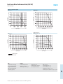
Festo Servo Motor Performance Data (110 VAC)
Torque as a Function of Speed
MTR-AC-40-...
MTR-AC-55-...
MTR-AC-55-...
Torque [Nm]
Torque [Nm]
Engineering Support
Speed [rpm]
Speed [rpm]
MTR-AC-100-3S-...
MTR-AC-100-...-3S
Torque [Nm]
Torque [Nm]
MTR-AC-70-...
Speed [rpm]
Speed [rpm]
Nominal torque
Peak torque
Note: these are calculated curves, the actual motor performance might vary up to 5%.
Note
Characteristic curves apply
to motors without gear unit.
The gear unit data must be
taken into consideration for
motors with gear unit.
Example
Nominal torque for motor
MTR-AC-55-3S-... at a
nominal speed of 3000 rpm
Without Gear Unit:
Nominal torque = 0.88 Nm
(see characteristic curve)
With Gear Unit:
Gear reduction ratio = 4:1
Gear unit efficiency = 0.95
Nominal rpm = 3000/4 = 750
Nominal torque = 0.88 Nm x 4 x 0.95 = 3.34 Nm
4
34
Multi-Axis Controllers and ServoWire® Digital Drives – Subject to change – 12/2006
Festo Servo Motor Performance Data (230 VAC)
Engineering Support
Torque as a Function of Speed
MTR-AC-40-...
Torque [Nm]
Torque [Nm]
MTR-AC-55-...
MTR-AC-55-...
Speed [rpm]
Speed [rpm]
MTR-AC-100-3S-...
MTR-AC-100-...-3S
Torque [Nm]
Torque [Nm]
MTR-AC-70-...
Speed [rpm]
Speed [rpm]
Nominal torque
Peak torque
Note
Characteristic curves apply
to motors without gear unit.
The gear unit data must be
taken into consideration for
motors with gear unit.
Example
Nominal torque for motor
MTR-AC-55-3S-... at a
nominal speed of 6800 rpm
Without Gear Unit:
Nominal torque = 0.66 Nm
(see characteristic curve)
With Gear Unit:
Gear reduction ratio = 4:1
Gear unit efficiency = 0.95
Nominal rpm = 6800/4 = 1700
Nominal torque = 0.66 Nm x 4 x 0.95 = 2.5 Nm
4
12/2006 – Subject to change – Multi-Axis Controllers and ServoWire® Digital Drives
35
System Selection
Engineering Support
System Selection Guide
Note
Selection of drive based on motor usage.
– Accelerations, speeds and torque requirements to be considered.
Ordering of drive communications cables:
If the system comprises of “N” number of drives, then the following cables will be required:
– 1 pc
Bilingual ServoWire Cable (between the controller and first drive)
– N-1 pc
Standard ServoWire Cable (between two consecutive drives)
4
Ordering of motor power and resolver cables, each motor requires:
– 1 motor power cable KMTR-AC…
– 1 motor resolver cable KRES-AC…
or
– 1 motor cable set KSEC-AC…
A one-time purchase of programming software (CoDeSys) is required.
– This CD includes the drive configuration software ServoWire Pro.
36
Multi-Axis Controllers and ServoWire® Digital Drives – Subject to change – 12/2006
System Selection
Engineering Support
Example #1
System Description: Three axis linear gantry
X axis:
Motor:
Homing:
Motor cables:
Over Travel sensors:
MTR-AC-3S-70-GA (without brake)
To a sensor
Motor is stationary so Hi-Flex cables are not required
Required at both ends of linear axis
Y axis:
Motor:
Homing:
Motor cables:
Over Travel sensors:
MTR-AC-3S-55-AA (without brake)
To a sensor
Hi-Flex cables are required
Required at both ends of linear axis
Z axis:
Motor:
Homing:
Motor cables:
Over Travel sensors:
MTR-AC-3S-40-AB (with brake)
To a hard stop
Hi-Flex cables are required
Required at both ends of linear axis
Required BOM For Example #1
Type Code
SEC-AC-SMLC-M3-SA
SEC-SDDR8/14-SA
SEC-SDDR4/7-SA
SEC-SDDR2/4-SA
KSDD-CLR-SW1-SA
KSDD-SDD-SW1-SA
KSEC-AC-S-3-SA
KSEC-AC-F-5-SA
P.SW-CDK-SA
SEC-SDD-BRK
DIOK-CONN-A-SDD-SA
KDIO-SMLC-5-SA
Description
Motion Controller
ServoWire Drive
ServoWire Drive
ServoWire Drive
ServoWire Bilingual cable 1m
ServoWire Cable 1m
Cable set for motor (Standard) 3m
Cable set for motor (Hi-Flex) 5m
CoDeSys Development Kit, CD-ROM*
Brake Unit Kit (optically isolated relay with diode)
I/O Connector with Cable for SEC-SDD Drives
Digital I/O Cable for SEC-AC-SMLC, 5 m
Part No.
13039603
13039608
13039607
13039606
13039612
13039610
13040215
13040219
13039641
13049327
13049328
13039973
Qty
01
01
01
01
01
02
01
02
01
03
01
01
Function
Controller (3-axis)
Drive for X axis
Drive for Y axis
Drive for Z axis
Comm. Cable: Controller to drive
Comm. Cable: Drive to drive
Cable set for X axis
Cable set for Y & Z axis
Programming /Config. Software
For motor brake (Z axis)
For drive I/O connections
Cable for I/O connection to controller
Example #2
System Description: Six-axis system with three pairs of synchronized axes. This system requires interfacing to several Profibus slave devices.
Axes 1 to 4:
Motor:
MTR-AC-3S-70-AB (with brake)
Homing:
To a sensor
Motor cables:
Motor is stationary so Hi-Flex cables are not required
Over Travel sensors:
Required at both ends of linear axis
Axes 5 and 6:
Motor:
Homing:
Motor cables:
Over Travel sensors:
MTR-AC-3S-55-AB (with brake)
To a sensor
Motor is stationary so Hi-Flex cables are not required
Required at both ends of linear axis
Required BOM For Example #2
Type Code
SEC-AC-SMLC-M8-PB-SA
SEC-SDDR8/14-SA
SEC-SDDR4/7-SA
KSDD-CLR-SW1-SA
KSDD-SDD-SW2-SA
KSEC-AC-S-5-SA
P.SW-CDK-SA
DIOK-CONN-A-SDD-SA
SEC-SDD-BRK
KDIO-SMLC-5-SA
Description
Motion Controller with Profibus Master
ServoWire Drive
ServoWire Drive
ServoWire Bilingual cable 1m
ServoWire Cable 2m
Cable set for motor (Standard) 5m
CoDeSys Development Kit, CD-ROM*
Brake Unit Kit (optically isolated relay with diode)
I/O Connector with Cable for SEC-SDD Drives
Digital I/O Cable for SEC-AC-SMLC, 5 m
Part No.
13040198
13039608
13039607
13039612
13039611
13040216
13039641
13049328
13049327
13039973
Qty
01
04
02
01
05
06
01
06
06
01
Function
Controller (8 axis)
Drives for axes 1 to 4
Drives for axes 5 and 6
Comm. Cable: Controller to drive
Comm. Cable: Drive to drive
Cable set for all axes
Programming /Config. Software
For motor brake (all axes)
For drive I/O connections
Cable for I/O connection to controller
4
Note
Line Filters SEC-SDD-LF… (optional) are recommended. Multiple SEC-SDD drives may share one line filter (per cabinet).
For sizing guideline, see page 39.
Regen Resistors SEC-SDD-RR… (optional) are required in applications dealing with large inertial loads operating at high speeds.
For sizing guideline, see page 39.
Order sensors for homing and over-travel protection (on linear axes): SIEN, SMT-8, SME-8 (see page 38).
12/2006 – Subject to change – Multi-Axis Controllers and ServoWire® Digital Drives
37
Sensor Selection
Engineering Support
Recommended Festo Sensors
Function
Type Code
Over Travel
Limit Sensors
on Drive
High Speed
Sensor/General
Input on Drive
General Purpose
Inputs on Drive
or SMLC
Controller
SIEN-M8B-PS-K-L
SIEN-M8B-PS-S-L
SIEN-M8B-NO-K-L
SIEN-M8B-NO-S-L
SMT-8-PS-K-LED-24-B
SMT-8-PS-S-LED-24-B
SME-8-K-LED-24
SME-8-S-LED-24
SME-8-O-K-LED-24
SIEN-M8B-PS-K-L
SIEN-M8B-PS-S-L
SIEN-M8B-PO-K-L
SIEN-M8B-PO-S-L
SIEN-M8B-NS-K-L
SIEN-M8B-NS-S-L
SIEN-M8B-NO-K-L
SIEN-M8B-NO-S-L
SMT-8-PS-K-LED-24-B
SMT-8-PS-S-LED-24-B
SMT-8-NS-K-LED-24-B
SMT-8-NS-S-LED-24-B
SME-8-K-LED-24
SME-8-S-LED-24
SME-8-O-K-LED-24
SIEN-M8B-PS-K-L
SIEN-M8B-PS-S-L
SIEN-M8B-PO-K-L
SIEN-M8B-PO-S-L
SIEN-M8B-NS-K-L
SIEN-M8B-NS-S-L
SIEN-M8B-NO-K-L
SIEN-M8B-NO-S-L
SMT-8-PS-K-LED-24-B
SMT-8-PS-S-LED-24-B
SMT-8-NS-K-LED-24-B
SMT-8-NS-S-LED-24-B
SME-8-K-LED-24
SME-8-S-LED-24
SME-8-O-K-LED-24
Part Number
Description
150386
150387
150388
150389
175436
175484
150855
150857
160251
150386
150387
150390
150391
150384
150385
150388
150389
175436
175484
171180
171181
150855
150857
160251
150386
150387
150390
150391
150384
150385
150388
150389
175436
175484
171180
171181
150855
150857
160251
Inductive sensor M8, PNP, NO, 3 wire
Inductive sensor M8, PNP, NO, 3 pin
Inductive sensor M8, NPN, NC, 3 wire
Inductive sensor M8, NPN, NC, 3 pin
Magneto- resistive, Slot, PNP, NO, 3 wire
Magneto- resistive, Slot, PNP, NO, 3 pin
Magnetic Reed, Slot, NO, 3 wire
Magnetic Reed, Slot, NO, 3 pin
Magnetic Reed, Slot, NC, 3 wire
Inductive sensor M8, PNP, NO, 3 wire
Inductive sensor M8, PNP, NO, 3 pin
Inductive sensor M8, PNP, NC, 3 wire
Inductive sensor M8, PNP, NC, 3 pin
Inductive sensor M8, NPN, NO, 3 wire
Inductive sensor M8, NPN, NO, 3 pin
Inductive sensor M8, NPN, NC, 3 wire
Inductive sensor M8, NPN, NC, 3 pin
Magneto- resistive, Slot, PNP, NO, 3 wire
Magneto- resistive, Slot, PNP, NO, 3 pin
Magneto- resistive, Slot, NPN, NO, 3 wire
Magneto- resistive, Slot, NPN, NO, 3 pin
Magnetic Reed, Slot, NO, 3 wire
Magnetic Reed, Slot, NO, 3 pin
Magnetic Reed, Slot, NC, 3 wire
External Pull-down
Resistor Requirements [kΩ]
3-6
3-6
None
None
3-6
3-6
None
None
None
5 - 10
5 - 10
5 - 10
5 - 10
None
None
None
None
5 - 10
5 - 10
None
None
None
None
None
3-6
3-6
3-6
3-6
None
None
None
None
3-6
3-6
None
None
None
None
None
4
38
Multi-Axis Controllers and ServoWire® Digital Drives – Subject to change – 12/2006
Regen Resistor/Drive Compatibility and Line Filter Selection and Sizing
Engineering Support
Regen Resistor/Drive Compatibility
Regen Resistor Model
SEC-SDD-RR-55
SEC-SDD-RR-95
SEC-SDD-RR-230
SEC-SDD-RR-650
SEC-SDD-RR-700
SEC-SDD-RR-845
Resistance
[Ω]
50
40
81
72
54
40
Rated Power
[Watts]
55
95
230
648
700
845
Drives SEC-SDDR8/14-SA
SEC-SDDE8/14-SA
Drives SEC-SDDR14/24-SA
SEC-SDDE14/24-SA
***
N/A
*
***
*
*
**
N/A
*
*
*
**
Key
* Compatible
** Peak Regen capacity of the drive
*** Limited by the resistor
Suitable for typical point-to-point motion
Suitable for continuous regenerative and overhauling loads
Line Filter Sizing and Selection Recommendations
In the case of a system using multiple SEC-SDD ServoWire drives, they may share one line filter per cabinet. When selecting the line filter size,
the fact that all drives/motors will not be operating at the same time needs to be taken into account.
Drive
SEC-SDD
ServoWire Drive
SEC-SDDR2/4-SA
SEC-SDDE2/4-SA
SEC-SDDR4/7-SA
SEC-SDDE4/7-SA
SEC-SDDR8/14-SA
SEC-SDDE8/14-SA
SEC-SDDR14/24-SA
SEC-SDDE14/24-SA
Mains Power
115 VAC, 1 Ph
230 VAC, 1 Ph
115 VAC, 1 Ph
230 VAC, 1 Ph
115 VAC, 1 Ph
230 VAC, 1 Ph
230 VAC, 3 Ph
115 VAC, 1 Ph
230 VAC, 1 Ph
230 VAC, 3 Ph
Drive Rated
Output Power kVA
0.29
0.59
0.49
0.98
0.58
1.17
1.95
0.98
1.97
3.32
Line Filter
Line Filter
SEC-SDD-LF15
[1 Ph]
SEC-SDD-LF30
[1 Ph]
SEC-SDD-LF30X
[3 Ph]
SEC-SDD-LF30X
[3 Ph]
Continuous
Current @ 230 VAC
Up to 15 A
Rated Power
kVA @ 230 VAC
3.45
Up to 30 A
6.90
Up to 30 A
11.70
Up to 30 A
11.70
System Examples
Example #1
A three-axis system comprising of two SEC-SDDR2/4-SA drives and one SEC-SDDR8/14-SA drive, all operating on 115 VAC single-phase.
– Line filter required: One SEC-SDD-LF15
[0.29 x 2 + 0.58 = 1.16 kVA]
Example #2
An eight-axis system comprising of eight SEC-SDDR14/24-SA drives operating on 230 VAC, three-phase.
– Line filter required: SEC-SDD-LF30X (one filter would be required if 4 drives are operating at a time).
[3.32 x 8 x 1.7321 = 46 kVA assuming all 8 drives operate simultaneously.
If 4 drives operate at a time, the power dissipation would be 11.5 kVA]
12/2006 – Subject to change – Multi-Axis Controllers and ServoWire® Digital Drives
4
39
Glossary
Engineering Support
A
E
Absolute encoder
A position feedback device
employed in motion control
systems to maintain a given
mechanical location. The
output of an absolute encoder
is representative of the absolute
position of the motor shaft
within one (or more - in the
case of a multi-turn encoder)
revolutions. Output is usually
a parallel digital word.
Electronic cam
A technique used to perform
non linear motion electronically
similar to that achieved with
mechanical cams.
Axis
In motion control, this term
normally refers to one of the
servomotors in the system,
either by name or Axis ID from
1 to 16. It is also used to refer
to any Master (Pacer) Encoders
in the system
C
CoDeSys
Controller Development System.
The IEC-61131-3 runtime system
developed by 3S Software used
on the SMLC.
CoDeSys IDE
The CoDeSys Integrated
Development Environment is
the Win32 based application
that allows you to develop,
download and debug SMLC
programs.
Command update rate
The rate at which the commands
will be sent from the motion
controller to the drive.
4
Coordinated motion
Multi-axis motion where
the position of each axis is
dependent on the other axis,
such that the path and velocity
of a move can be accurately
controlled.
Electronic gearing
A method that simulates
mechanical gears by electrically
synchronizing one closed loop
axis to a second axis (open or
closed loop) through a variable
ratio.
Electronic line shaft
A virtual axis that is used as
the master axis on a machine
to which other axes are
synchronized by electronic
gearing or camming profiles.
Electromagnetic compatibility
EMC is the ability of a device
or a system to operate
satisfactorily in its electromagnetic environment without
emitting unacceptable electromagnetic interference to other
devices.
Encoder resolution
Measure of the smallest
positional change which can
be detected by the encoder.
F
Follower
A servo axis, which is controlling
its motion as a function of motion
data, generated by a pacer axis.
Following error
The difference between the
commanded position of an
axis and its actual position.
The amount of following error
present varies with the speed
of the axis.
FireWire
Bus standard for industrial
applications and digital
data exchange at high speed
between various devices
(IEEE 1394).
40
Feed Forward
A technique used to
pre-compensate a control
loop for known errors due
to motor, drive, or load
characteristics. Provides
improved response. This
technique depends only
on the command and not
the error.
L
Loop update rate (loop closure)
The rate at which the torque,
velocity and position loops are
closed in the drive. Loop update
involves the regulation of the
commanded and the actual
variable (torque, position, or
velocity) in order to minimize
the error between the actual
and commanded variable.
H
Home Position
A reference position in a
motion control system
derived from a mechanical
datum or switch.
M
I
MODBUS
The MODBUS® Protocol is a
messaging structure developed
by Modicon in 1979, to establish
master-slave/client-server
communication between
intelligent devices. It is a de facto
standard, truly open and a widely
used network protocol in the
industrial manufacturing
environment.
IEC-61131-3
A global standard defining
programming languages for
industrial control.
Incremental encoder
A type of feedback device
which converts mechanical
motion into electrical signals
(pulses) to indicate motor
shaft position. By counting
these pulses the motor shaft
position can be determined.
The frequency of the pulses
reflects the speed at which
the motor is rotating. Encoders
with quadrature output provide
information on the direction
of motion using the phase
relationship of the two channels.
Interpolation
Internal calculation by the
controller of intermediate
points on a path in a time grid.
The path is pre-defined with
interpolation points.
The intermediate points can
be on a straight line (linear
interpolation), on a circle
(circular interpolation), or
on a parabola (parabolic
interpolation). The path data
is used for simultaneous control
of motion axes.
Master axis
Motion axis in a drive system
which controls the synchronized
motion of at least one drive axis.
MODBUS/TCP
Modbus/TCP is an
implementation of the
MODBUS Protocol, allowing
MODBUS messages to be
transferred via Ethernet.
N
Noise
An unwanted electrical signal.
Typically from RFI or EMI induced
onto the drive’s components,
speed reference or feedback
wiring, and can cause the axis
to react unexpectedly. Sources
of noise are AC power lines,
motors, generators, transformers,
fluorescent lights, CRT displays,
and radio transmitters.
Multi-Axis Controllers and ServoWire® Digital Drives – Subject to change – 12/2006
Glossary
Engineering Support
O
R
OPC
OLE for Process Control. A set of
open standards for connectivity
and interoperability of industrial
automation and enterprise
systems.
RTOS
Real-Time Operating System.
P
Pacer encoder
An incremental encoder or
device that generates quadrature
signals which are used by other
servo axes when they operate as
followers.
PLCopen
Association of manufacturers
and users of programming logic
controllers and programming
systems to promote the
IEC 1131-3 standard (PLC
programming) and certify
programming systems based
on it. This includes the definition
of various compliance levels as
well as the development of test
procedures and the award of
certificates by independent
institutions. The programming
language IEC 61131-3 is also
substantially supported.
Q
Quadrature
Quadrature or "phase
quadrature" signals are the
most commonly used method
of electronically determining
or transmitting bidirectional
position information.
The two-quadrature signals
are digital square waves, which
have their cycles displaced
90 degrees (of the 360 electrical
degrees in the repeated
waveform). All four edges of
the two digital signals are
normally used for the maximum
possible position resolution
("4X").
Regeneration
Usually refers to a circuit in
a drive amplifier that accepts
and drains energy produced
by a rotating motor either during
deceleration or free-wheel
shutdown. In some systems,
this regen power can be used
by other axis.
Registration control
The act of maintaining a fixed
position relationship between
machine tooling and a product
in the machine. Registration is
normally measured by capturing
the tooling position with
respect to the product using a
registration sensor of some type.
It is controlled by phasing the
tooling ahead or behind based
on the difference between the
actual and desired positional
orientation.
Resolver
A position transducer used to
determine the position of a
motor. Resolvers are rotary
transformer devices with
analog interfaces. However,
in Festo motion control
systems which use resolvers,
the servodrive decodes the
resolver position digitally.
S
Servo drive
A motor drive which utilizes
internal feedback loops for
accurate control of motor
current and/or velocity. It is
the electronics which convert
low level command signals to
high power voltages and currents
to operate a servomotor.
Slave axis
A motion axis that is derived and
driven by synchronization with
the master axis.
Synchronization
The condition that occurs
when several axes follow a
common control signal and
are in a specific position or
at a specific speed according
to the signal.
T
TCP/IP
Transmission Control Protocol
over Internet Protocol. The
de facto standard Ethernet
protocol.
Tension control
Using Tension feedback to
control the velocity of a
servomotor.
Tuning
In a servo system, the process
of optimizing loop parameters
to achieve the desired response
from a stage or mechanism from
an input command.
S curve
S curve refers to a control pattern
that accelerates and decelerates
a motor slowly to reduce
mechanical shock.
Servo motor
A motor which is used in closed
loop systems where feedback is
used to control motor velocity,
position, or torque.
12/2006 – Subject to change – Multi-Axis Controllers and ServoWire® Digital Drives
4
41
Electromechanical Actuators and Servo Motors
ServoWire Digital Drives
Multi-Axis Controller
Festo servo motors, type MTR-AC and ServoWire
digital drives offer tried and tested performance
with the SEC-AC-SMLC controllers and Festo
electric linear actuators types DGE and SLME.
ServoWire
(FireWire)
DGE Actuator
DGE Actuator
MTR-AC Motors
SLME Actuator
DGE Electric Linear Actuators
Ball Screw Driven
Linear Actuators
Sizes: 18, 25, 40, 63 mm
Stroke lengths up to 2 m
Maximum speed: 1.2 m/s
Repeatability of ±0.02 mm
Axial force up to 1,600 N
Boom Axis
Sizes: 18, 25, 40 mm
Stroke lengths up to 1 m
Maximum speed: 3 m/s
Repeatability of ±0.05 mm
Axial force up to 1,000 N
Multi-axis Systems
Components and accessories
to build:
X/Y/Z Axis Systems
Cantilever-type Handling
Gantries
Linear Gantries
Planar Surface Gantries
Ball Screw Driven
Linear Actuators
Sizes: 23, 30, 46 mm
Stroke lengths up to 1000 mm
Maximum speed: 1.05 m/s
Repeatability of ±0.005 mm
Axial force up to 3,200 N
Positioning accuracy
to 0.060 mm
Maximum dynamic
load of 27 kN
Design Features
Compact via gothic arch
bearing configuration
Minimal deflection with
steel U-shaped guide rail
Corrosion resistant surfaces
ensure predictable life
Cleanroom compatible with
C-Grease lubrication
Optional dust cover protects
ball bearings from debris
Applications
Semiconductor manufacturing
Medical devices and laboratory
automation
Easy-to-install/configure into
single or multi-axis systems
Compact design for envelope
constraints
Adheres to high quality control
standards
Overview
Sizes: 40, 55, 70, 100 mm
With holding brake and
gearbox options
Rotor position sensor: resolver
c UL us - recognized (OL)
CE symbol according to
EU low voltage guidelines
MTR-AC-40-...
Max. speed: 10,400 1/min
Nominal speed: 6,000 1/min
Peak torque: 1 Nm
Nominal torque: 0.24 Nm
Standstill torque: 0.27 Nm
MTR-AC-70-...
Max. speed: 11,640 1/min
Nominal speed: 6,250 1/min
Peak torque: 3.1 Nm
Nominal torque: 1.4 Nm
Standstill torque: 1.64 Nm
MTR-AC-55-...
Max. speed: 8,090 1/min
Nominal speed: 6,800 1/min
Peak torque: 2.8 Nm
Nominal torque: 0.66 Nm
Standstill torque: 0.98 Nm
MTR-AC-100-...
Max. speed: 4,550 1/min
Nominal speed: 3,600 1/min
Peak torque: 23 Nm
Nominal torque: 6.36 Nm
Standstill torque: 12.53 Nm
Belt Driven Linear Actuators
Sizes: 8, 12, 18, 25, 40, 63 mm
Stroke lengths up to 5 m
Maximum speed: 10 m/s
Repeatability of ±0.10 mm
Axial force up to 1,500 N
SLME Electric Actuators
MTR-AC Servo Motors
42
Multi-Axis Controllers and ServoWire® Digital Drives – Subject to change – 12/2006
Product Range and Company Overview
Supporting Advanced Automation... As No One Else Can
Festo is a leading global manufacturer of pneumatic and electromechanical systems, components and controls for industrial automation,
with 56 national headquarters serving more than 180 countries. For more than 80 years, Festo has continuously elevated the state
of manufacturing with innovations and optimized motion control solutions that deliver higher performance, more profitable automated
manufacturing and processing equipment. Our dedication to the advancement of automation extends beyond technology to the
education of current and future automation and robotics designers with simulation tools, teaching programs, and on-site services.
Custom Automation Components
Custom Control Cabinets
Complete Systems
Custom Designed Automation Solutions
Our experienced engineers provide complete support at every stage of your development process, including:
conceptualization, analysis, engineering, design, assembly, documentation, validation, and production.
Electromechanical
Pneumatics
PLCs and I/O Devices
Comprehensive Line of Automation Components
With a comprehensive line of more than 30,000 automation components,
Festo can support the most complex automation requirements.
Quality Assurance, ISO 9001 Certification
Festo Corporation is committed to provide Festo
products and services that will meet or exceed
our customers’ requirements in product quality,
delivery, customer service and satisfaction.
All Festo locations within the United States
are registered to ISO 9001.
© Copyright 2006, Festo Corporation. While every effort is made to ensure that all dimensions and specifications are correct, Festo cannot guarantee that
publications are completely free of any error, in particular typing or printing errors. Accordingly, Festo cannot be held responsible for the same. For Liability and
Warranty conditions, refer to our "Terms and Conditions of Sale", available from your local Festo office. All rights reserved. No part of this publication may be
reproduced, distributed, or transmitted in any form or by any means, electronic, mechanical, photocopying or otherwise, without the prior written permission of Festo.
All technical data subject to change according to technical update.
Festo North America
United States
Customer Resource Center
502 Earth City Expressway, Suite 125
Earth City, MO 63045
Design and Manufacturing Facilities
For ordering assistance,
or to find your nearest Festo Distributor,
Call: 1.800.99.FESTO
Fax: 1.800.96.FESTO
Email: [email protected]
For technical support,
Call: 1.866.GO.FESTO
Fax: 1.800.96.FESTO
Email: [email protected]
Headquarters
Festo Corporation
395 Moreland Road
P.O. Box 18023
Hauppauge, NY 11788
www.festo.com/us
East: 395 Moreland Road, Hauppauge, NY 11788
Sales Offices
Appleton
North 922 Tower View Drive, Suite N
Greenville, WI 54942
Boston
120 Presidential Way, Suite 330
Woburn, MA 01801
Charlotte
4301-S Stuart Andrew Blvd.
Charlotte, NC 28217
Central: 1441 East Business Center Drive, Mt. Prospect, IL 60056
Chicago
1441 East Business Center Drive
Mt. Prospect, IL 60056
Dallas
1825 Lakeway Drive, Suite 600
Lewisville, TX 75057
Detroit
2601 Cambridge Court, Suite 320
Auburn Hills, MI 48326
New York
395 Moreland Road
Hauppauge, NY 11788
Silicon Valley
2800 Collier Canyon Road
Livermore, CA 94551
West: 2800 Collier Canyon Road, Livermore, CA 94550
Mexico
Canada
Headquarters
Festo Pneumatic, S.A.
Av. Ceylán 3
Col. Tequesquinahuac
54020 Tlalnepantla
Edo. de México
Phone:011 52 [55] 53 21 66 00
Fax: 011 52 [55] 53 21 66 65
Email: [email protected]
www.festo.com/mx
Headquarters
Festo Inc.
5300 Explorer Drive
Mississauga, Ontario L4W 5G4
Phone: 1.905.624.9000
Fax: 1.905.624.9001
Email: [email protected]
www.festo.com/ca
Festo Worldwide
Argentina
Estonia
Latvia
Australia
Finland
Lithuania
Singapore
Austria
France
Malaysia
Belarus
Germany
Mexico
Belgium
Great Britain
Brazil
Bulgaria
Greece
Netherlands
Slovakia Slovenia South Africa South Korea
New Zealand
Spain
Canada
Hong Kong
Chile
Hungary
Norway
China
India
Peru
Sweden Switzerland
Colombia
Indonesia
Philippines
Croatia
Iran
Poland
Czech Republic
Ireland
Israel
Romania
Taiwan Thailand Turkey Ukraine
Denmark
Italy
Russia
Japan
Serbia
United States Venezuela
www.festo.com
Subject to change
Catalog No.: 13044699 12.06