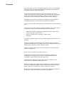
1
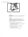
867
Spezialnähmaschine
Betriebsanleitung
Instruction manual
Instructions d’emploi
Postfach 17 03 51, D-33703 Bielefeld • Potsdamer Straße 190, D-33719 Bielefeld
Telefon +49 (0) 521 / 9 25-00 • Telefax +49 (0) 521 / 9 25 24 35 • www.duerkopp-adler.com
Ausgabe / Edition:
01/2008
Änderungsindex
Rev. index: 02.0
Printed in Federal Republic of Germany
Teile-Nr./Part.-No.:
0791 867740
D
GB
F
Alle Rechte vorbehalten.
Eigentum der Dürkopp Adler AG und urheberrechtlich geschützt. Jede, auch auszugsweise Wiederverwendung
dieser Inhalte ist ohne vorheriges schriftliches Einverständnis der Dürkopp Adler AG verboten.
All rights reserved.
Property of Dürkopp Adler AG and copyrighted. Reproduction or publication of the content in any manner, even
in extracts, without prior written permission of Dürkopp Adler AG, is prohibited.
Tous droits réservés.
Propriété de la société Dürkopp Adler AG et protégé par la loi sur le droit d’auteur. Une copie ou reproduction
par quelque procédé que ce soit du contenu sans accord écrite de l’auteur est interdite.
Copyright © Dürkopp Adler AG - 2008
Foreword
This instruction manual is intended to help the user to become familiar
with the machine and take advantage of its application possibilities in
accordance with the recommendations.
The instruction manual contains important information on how to
operate the machine securely, properly and economically. Observation
of the instructions eliminates danger, reduces costs for repair and
down-times, and increases the reliability and life of the machine.
The instruction manual is intended to complement existing national
accident prevention and environment protection regulations.
The instruction manual must always be available at the machine/sewing
unit.
The instruction manual must be read and applied by any person that is
authorized to work on the machine/sewing unit. This means:
–
–
–
Operation, including equipping, troubleshooting during the work
cycle, removing of fabric waste,
Service (maintenance, inspection, repair) and/or
Transport.
The user also has to assure that only authorized personnel work on the
machine.
The user is obliged to check the machine at least once per shift for
apparent damages and to immediatly report any changes (including the
performance in service), which impair the safety.
The user company must ensure that the machine is only operated in
perfect working order.
Never remove or disable any safety devices.
If safety devices need to be removed for equipping, repairing or
maintaining, the safety devices must be remounted directly after
completion of the maintenance and repair work.
Unauthorized modification of the machine rules out liability of the
manufacturer for damage resulting from this.
Observe all safety and danger recommendations on the machine/unit!
The yellow-and-black striped surfaces designate permanend danger
areas, eg danger of squashing, cutting, shearing or collision.
Besides the recommendations in this instruction manual also observe
the general safety and accident prevention regulations!
General safety instructions
The non-observance of the following safety instructions can cause
bodily injuries or damages to the machine.
1. The machine must only be commissioned in full knowledge of the
instruction book and operated by persons with appropriate training.
2. Before putting into service also read the safety rules and
instructions of the motor supplier.
3. The machine must be used only for the purpose intended. Use of
the machine without the safety devices is not permitted. Observe all
the relevant safety regulations.
4. When gauge parts are exchanged (e.g. needle, presser foot, needle
plate, feed dog and bobbin) when threading, when the workplace is
left, and during service work, the machine must be disconnected
from the mains by switching off the master switch or disconnecting
the mains plug.
5. Daily servicing work must be carried out only by appropriately
trained persons.
6. Repairs, conversion and special maintenance work must only be
carried out by technicians or persons with appropriate training.
7. For service or repair work on pneumatic systems, disconnect the
machine from the compressed air supply system (max. 7-10 bar).
Before disconnecting, reduce the pressure of the maintenance unit.
Exceptions to this are only adjustments and functions checks made
by appropriately trained technicians.
8. Work on the electrical equipment must be carried out only by
electricians or appropriately trained persons.
9. Work on parts and systems under electric current is not permitted,
except as specified in regulations DIN VDE 0105.
10. Conversion or changes to the machine must be authorized by us
and made only in adherence to all safety regulations.
11. For repairs, only replacement parts approved by us must be used.
12. Commissioning of the sewing head is prohibited until such time as
the entire sewing unit is found to comply with EC directives.
13. The line cord should be equipped with a country-specific mains
plug. This work must be carried out by appropriately trained
technicians (see paragraph 8).
It is absolutely necessary to respect the safety
instructions marked by these signs.
Danger of bodily injuries !
Please note also the general safety instructions.
Contents
page:
Preface and general safety instructions
Part 1: Operating Instructions Class 867
(Edition 01/2008)
1.
Product description . . . . . . . . . . . . . . . . . . . . . . . . . . . . . . . . . . . . . . . . . . . .
5
2.
Designated use . . . . . . . . . . . . . . . . . . . . . . . . . . . . . . . . . . . . . . . . . . . . . . .
5
3.
Subclasses . . . . . . . . . . . . . . . . . . . . . . . . . . . . . . . . . . . . . . . . . . . . . . . . . .
6
4.
Optional equipment . . . . . . . . . . . . . . . . . . . . . . . . . . . . . . . . . . . . . . . . . . . .
9
5.
5.1
Technical data
Technical data Subclasses . . . . . . . . . . . . . . . . . . . . . . . . . . . . . . . . . . . . . . . . .
17
6.
6.1
6.1.1
6.1.2
6.2
6.2.1
6.2.2
Operation
Threading the needle thread . . . . . . . . . . . . . . . . . . . . . . . . . . . . . . . . . . . .
Threading the needle thread on machine without short thread cutter . . . . . . . . . . . .
Threading the needle thread on machine with short thread cutter . . . . . . . . . . . . . .
Adjusting the needle-thread tension . . . . . . . . . . . . . . . . . . . . . . . . . . . . . . .
Adjusting the needle-thread tension on automotive machines . . . . . . . . . . . . . . . .
Function of the thread main tension and the thread supplementary tension in relation
to the sewing foot lifting . . . . . . . . . . . . . . . . . . . . . . . . . . . . . . . . . . . . . . .
6.2.3 Reparation seam with thread tension always closed . . . . . . . . . . . . . . . . . . . . . .
6.2.4 Function of the thread’s supplementary tension in relation to the stroke adjustment
and the Speedomat. . . . . . . . . . . . . . . . . . . . . . . . . . . . . . . . . . . . . . . . . .
6.3
Opening the thread tension . . . . . . . . . . . . . . . . . . . . . . . . . . . . . . . . . . . . .
6.4
Switching the supplementary tension on and off with machines without thread trimmer
6.5
Adjusting the thread regulator . . . . . . . . . . . . . . . . . . . . . . . . . . . . . . . . . . .
6.6
Winding on the hook thread. . . . . . . . . . . . . . . . . . . . . . . . . . . . . . . . . . . . .
6.7
Changing the hook-thread bobbin . . . . . . . . . . . . . . . . . . . . . . . . . . . . . . . . .
6.7.1 Inserting the hook thread bobbin with machines equipped with residual thread monitor
6.8
Setting the hook thread tension . . . . . . . . . . . . . . . . . . . . . . . . . . . . . . . . . .
6.9
Inserting and changing the needle with single-needle machines . . . . . . . . . . . . . .
6.10 Inserting and changing the needle with double-needle machines . . . . . . . . . . . . . .
6.11 Lifting the sewing foot . . . . . . . . . . . . . . . . . . . . . . . . . . . . . . . . . . . . . . . .
6.12 Locking the sewing feet in lifted position . . . . . . . . . . . . . . . . . . . . . . . . . . . . .
6.13 Sewing-foot pressure . . . . . . . . . . . . . . . . . . . . . . . . . . . . . . . . . . . . . . . .
6.13.1 Adjusting the sewing foot pressure on automotive machines . . . . . . . . . . . . . . . . .
6.14 Sewing-foot stroke . . . . . . . . . . . . . . . . . . . . . . . . . . . . . . . . . . . . . . . . . .
6.14.1 Adjusting the sewing foot stroke on automotive machines . . . . . . . . . . . . . . . . . .
6.15 Setting the stitch length . . . . . . . . . . . . . . . . . . . . . . . . . . . . . . . . . . . . . . .
6.15.1 Adjusting the stitch length on automotive machines . . . . . . . . . . . . . . . . . . . . . .
6.16 Key pad on the machine arm . . . . . . . . . . . . . . . . . . . . . . . . . . . . . . . . . . . .
GB
.
.
.
.
.
.
.
.
.
.
.
.
.
.
.
21
21
23
25
25
. . . .
. . . .
26
26
.
.
.
.
.
.
.
.
.
.
.
.
.
.
.
.
.
.
.
27
27
28
29
30
31
32
33
34
35
36
37
37
37
38
39
41
42
43
.
.
.
.
.
.
.
.
.
.
.
.
.
.
.
.
.
.
.
.
.
.
.
.
.
.
.
.
.
.
.
.
.
.
.
.
.
.
.
.
.
.
.
.
.
.
.
.
.
.
.
.
.
.
.
.
.
.
.
.
.
.
Contents
page:
7.
7.1
Efka DC1600/DA82GA direct-current positioning actuator
General . . . . . . . . . . . . . . . . . . . . . . . . . . . . . . . . . . . . . . . . . . . . . . . . . . . . .
44
8.
8.1
Efka VD552/6F82FA coupling-positioning actuator
General . . . . . . . . . . . . . . . . . . . . . . . . . . . . . . . . . . . . . . . . . . . . . . . . . . . . .
45
9.
9.1
Efka DC1550/DA321G direct-current positioning drive
General . . . . . . . . . . . . . . . . . . . . . . . . . . . . . . . . . . . . . . . . . . . . . . . . . . . . .
45
10.
Sewing . . . . . . . . . . . . . . . . . . . . . . . . . . . . . . . . . . . . . . . . . . . . . . . . . . . . .
46
11.
11.1
11.2
Maintenance
Cleaning and testing . . . . . . . . . . . . . . . . . . . . . . . . . . . . . . . . . . . . . . . . . . . . .
Lubrication . . . . . . . . . . . . . . . . . . . . . . . . . . . . . . . . . . . . . . . . . . . . . . . . . . .
48
50
1.
Product description
The DÜRKOPP ADLER 867 is a special sewing machine for universal
use.
·
·
·
·
·
·
·
·
It is a flatbed double-lockstitch machine with bottom feed, needle
feed and alternating upper foot feed.
Depending on the subclass it comes as single or double needle
automat, with or without electromagnetic thread cutter, with or
without edge trimmer.
Equipped with a large or oversized two-piece vertical hook.
With a maximum of 20 mm fabric clearance when sewing feet are
lifted.
The residual thread length after thread trimming is about 15 mm
without short thread trimming device and about 7 mm with short
thread trimming device.
A safety clutch prevents a changing of the hook setting or a hook
damage in the case of a thread deflection into the shuttle track.
Automatic wick lubricating with an inspection glass on the arm for
machine and hook lubrication.
Integrated winder.
GB
2.
Designated use
The 867 is a sewing machine designed for sewing light to
medium-heavy material. Such material is generally made of textile
fibres, but it may also be leather. It is used in the clothing industry and
for domestic and motor-vehicle upholstery.
This special sewing machine can also be used to produce so-called
technical seams. In this case, however, the operator must assess the
possible dangers which may arise (with which DÜRKOPP ADLER AG
would be happy to assist), since such applications are on the one hand
relatively unusual and, on the other, so varied that no single set of
criteria can cover them all. The outcome of this assessment may
require appropriate safety measures to be taken.
Generally only dry material may be sewn with this machine. The
material may be no thicker than 10 mm when compressed by the
lowered sewing feet. The material may not contain any hard objects,
since if it does the machine may not be operated without an
eye-protection device. No such device is currently available.
The seam is generally produced with textile-fibre sewing thread of
gauge up to 11/3 NeB (cotton), 11/3 Nm (synthetic) or 11/4 Nm
(covering yarn).
Before using any other thread the possible dangers arising must be
assessed and appropriate safety measures taken if necessary.
5
This special sewing machine may be set up and operated only
in dry, well-maintained premises. If the sewing machine is used in
premises which are not dry and well-maintained it may be
necessary to take further precautions (which should be agreed in
advance - see EN 60204-31:1999).
As manufacturers of industrial sewing machines we proceed on the
assumption that personnel who work on our products will have
received training at least sufficient to acquaint them with all normal
operations and with any hazards which these may involve.
3.
6
Subclasses
867-190020
Single-needle double-lockstitch machine with bottom
feed, needle feed, alternating upper foot feed and
large hook.
867-190040
Single-needle double-lockstitch machine with bottom
feed, needle feed, alternating upper foot feed and
oversized hook (XXL).
867-290020
Double-needle double-lockstitch machine with
bottom feed, needle feed, alternating upper foot feed
and large hook.
867-290040
Double-needle double-lockstitch machine with
bottom feed, needle feed, alternating upper foot feed
and oversized hook (XXL).
867-190122
Single-needle double-lockstitch machine with bottom
feed, needle feed, alternating upper foot feed,
electro-magnetic thread cutter, electro-magnetic
seam bartacking and sewing foot lifting.
With large hook.
867-190142
Single-needle double-lockstitch machine with bottom
feed, needle feed, alternating upper foot feed,
electro-magnetic thread cutter, electro-magnetic
seam bartacking and sewing foot lifting.
With oversized hook (XXL).
867-190145
Single-needle double-lockstitch machine with bottom
feed, needle feed, alternating upper foot feed,
electro-magnetic short thread cutter,
electro-magnetic seam bartacking and sewing foot
lifting.
With oversized hook (XXL).
867-190322
Single-needle double-lockstitch machine with bottom
feed, needle feed, alternating upper foot feed,
electro-pneumatic rapid stroke adjustment,
electro-magnetic thread cutter, connectable thread
tension, electro-pneumatic seam bartacking,
electro-pneumatic second stitch length and sewing
foot lifting.
With large hook.
867-190342
Single-needle double-lockstitch machine with bottom
feed, needle feed, alternating upper foot feed,
electro-pneumatic rapid stroke adjustment,
electro-magnetic thread cutter, connectable thread
tension, electro-pneumatic seam bartacking,
electro-pneumatic second stitch length and sewing
foot lifting.
With oversized hook (XXL).
867-190445
Single-needle double-lockstitch machine with bottom
feed, needle feed, alternating upper foot feed,
electro-pneumatic rapid stroke adjustment,
electro-magnetic short thread cutter, connectable
thread tension, electro-pneumatic seam bartacking,
electro-pneumatic second stitch length and sewing
foot lifting.
With oversized hook (XXL).
867-290322
Double-needle double-lockstitch machine with
bottom feed, needle feed, alternating upper foot
feed, electro-pneumatic rapid stroke adjustment,
electro-magnetic thread cutter, connectable thread
tension, electro-pneumatic seam bartacking,
electro-pneumatic second stitch length and sewing
foot lifting.
With large hook.
867-290342
Double-needle double-lockstitch machine with
bottom feed, needle feed, alternating upper foot
feed, electro-pneumatic rapid stroke adjustment,
electro-magnetic thread cutter, connectable thread
tension, electro-pneumatic seam bartacking,
electro-pneumatic second stitch length and sewing
foot lifting.
With oversized hook (XXL).
867-290445
Double-needle double-lockstitch machine with
bottom feed, needle feed, alternating upper foot
feed, electro-pneumatic rapid stroke adjustment,
electro-magnetic short thread cutter, connectable
thread tension, electro-pneumatic seam bartacking,
electro-pneumatic second stitch length and sewing
foot lifting.
With oversized hook (XXL).
867-392342
Single-needle double-lockstitch machine with
no-stroke lower feed, with needle feed, alternating
upper foot feed, electro-pneumatic thread
cutter, connectable thread tension,
electro-pneumatic seam bartacking,
electro-pneumatic rapid stroke adjustment and
sewing foot lifting. With oversized hook (XXL).
Equipped with moving variable binding device.
867-393342
Single-needle double-lockstitch machine with
no-stroke lower feed, with needle feed, alternating
upper foot feed, electro-pneumatic thread
cutter, connectable thread tension,
electro-pneumatic seam bartacking,
electro-pneumatic rapid stroke adjustment and
sewing foot lifting. With oversized hook (XXL).
Equipped with electromotor driven edge cutter.
867-394342
Single-needle double-lockstitch machine with
no-stroke lower feed, with needle feed, alternating
upper foot feed, electro-pneumatic thread
cutter, connectable thread tension,
electro-pneumatic seam bartacking,
electro-pneumatic rapid stroke adjustment and
sewing foot lifting. With oversized hook (XXL).
Equipped with electromotor driven edge cutter and
moving variable binding device.
GB
7
8
867-190040-70
700 mm long arm flatbed single-needle
double-lockstitch machine with bottom feed, needle
feed, alternating upper foot feed. With oversized
hook (XXL).
867-190342-70
700 mm long arm flatbed single-needle
double-lockstitch machine with bottom feed, needle
feed, alternating upper foot feed, electro-pneumatic
rapid stroke adjustment, electro-magnetic thread
cutter, connectable thread tension,
electro-pneumatic seam bartacking,
electro-pneumatic second stitch length and sewing
foot lifting.
With oversized hook (XXL) and integrated sewing
light.
867-290040-70
700 mm long arm flatbed double-needle
double-lockstitch machine with bottom feed, needle
feed, alternating upper foot feed
With oversized hook (XXL).
867-290342-70
700 mm long arm flatbed double-needle
double-lockstitch machine with bottom feed, needle
feed, alternating upper foot feed, electro-pneumatic
rapid stroke adjustment, electro-magnetic thread
cutter, connectable thread tension,
electro-pneumatic seam bartacking,
electro-pneumatic second stitch length and sewing
foot lifting.
With oversized hook (XXL) and integrated sewing
light.
4.
Optional equipments
For the 867 the following optional equipments are available:
Optional equipment
Subclasses
0867 590014
Electro-pneumatic needle cooler
from the top
x x x x x x
0867 590024
Electro-pneumatic needle cooler
from the bottom
x x x x x x
0867 590104
Thread monitor for hook thread
large hook, single-needle
867-190020
867-190040
867-190122
867-190142
867-190145
867-190322
867-190342
867-190445
867-290020
867-290040
867-290322
867-290342
867-290445
867-392342
867-393342
867-394342
Order No.
0867 590124
0867 590114
0867 590134
0867 590164
0867 590174
9780 000108
x
x
Thread monitor for hook thread
large hook, double-needle
x
Thread monitor for hook thread
oversized hook (XXL), single-needle
x
x
GB
Thread monitor for hook thread
oversized hook (XXL), double-needle
x
Thread monitor for hook thread short
thread cut., large hook, single-needle
x
x
Thread monitor for hook thread short
thread cut., XXL hook, double-needle
x
WE-8 maintenance unit for pneumatic
optional equipments
x x x x x x x x x x x x x x x
x
9822 510001
Halogen sewing lamp
x x x x x x x x x x x x x x x
x
9880 867100
Sewing lamp add-on kit
x x x x x x x x x x x x x x x
x
0798 500088
Sewing lamp transformer
x x x x x x x x x x x x x x x
x
0797 003031
Pneumatic connection package
x x x x x x x x x x x x x x x
x
N800 080001
Edge guide, swivelling
x x x x x x x x x
N800 080004
Roller stop
x x x x x x x x x
N800 005650
Seam center guide
0867 590364
Pneumatic sewing foot lifting
x x x
x x
x x
x = Optional equipment
o = Standard equipment
9
Optional equipment
Subclasses
9880 867103
Sewing lamp LED
x x x x x x x x x x x x x x x
x
9822 560001
Power supply for sewing lamp LED
x x x x x x x x x x x x x x x
x
9880 867102
Integrated sewing lamp LEDs
x x x x x o o o x x o o o o o
o
9850 001075
Power supply complete for
integrated sewing lamp LEDs
x x x x x o o o x x o o o o o
o
0367 595124
Mechanical sewing foot lifting
x x
N800 080021
Edge guide, swivelling
x x x x x x x x
N800 080022
Edge guide / Rule on the slide of the
throat plate (2nd seam distance)
x x x x x x x x
867-190020
867-190040
867-190122
867-190142
867-190145
867-190322
867-190342
867-190445
867-290020
867-290040
867-290322
867-290342
867-290445
867-392342
867-393342
867-394342
Order No.
N800 005646
Edge guide pneumatic driven with
adjustable seam distances /
fixed on the slide of the throat plate
N800 005655
Seam center guide, swivelling
0867 590074
Reflected light barrier for the automatic
recognition of the material edge at
the end of seam
9805 791113
0667 156224
USB memory key
for transferring data with the
Efka control unit DA321G
CLB 300 hook
Core-Less-Bobbin
x x
x x x x x x x x
x x x x x
x x x x x x
x x x x x x x x
x
x x x
x x x x x
x
x x x x x x x x x x
x
x
Stands
MG55 400304
Stand set MG 55-3
for motor fitting beneath the table,
with pedal
Table top size 1060 x 500 mm
MG55 400314
Stand set MG 55-3
for motor fixed on machine head,
with pedal
Table top size 1060 x 500 mm
x = Optional equipment
o = Standard equipment
10
x x x x
x x x x x x
x x x
Optional equipment
Subclasses
0867 590014
Electro-pneumatic needle cooler
from the top
x x
0867 590024
Electro-pneumatic needle cooler
from the bottom
x x
0867 590104
Thread monitor for hook thread
large hook, single-needle
0867 590124
Thread monitor for hook thread
large hook, double-needle
0867 590114
Thread monitor for hook thread
oversized hook (XXL), single-needle
867-190040-70
867-190342-70
867-290040-70
867-290342-70
Order No.
0867 590134
x
Thread monitor for hook thread
oversized hook (XXL), double-needle
GB
x
0867 590164
Thread monitor for hook thread short
thread cut., large hook, single-needle
0867 590174
Thread monitor for hook thread short
thread cut., XXL hook, double-needle
9780 000108
WE-8 maintenance unit for pneumatic
optional equipments
x x x x
9822 510001
Halogen sewing lamp
x x x x
9880 867100
Sewing lamp add-on kit
x x x x
0798 500088
Sewing light transformer
x x x x
0797 003031
Pneumatic connection package
x x x x
N800 080001
Edge guide, swivelling
x x x x
N800 080004
Roller stop
x x x x
N800 005650
Seam center guide
0867 590364
Pneumatic sewing foot lifting
x x
x = Optional equipment
o = Standard equipment
11
Optional equipment
Subclasses
9880 867103
Sewing lamp LED
x x x x
9822 560001
Power supply for sewing lamp LED
x x x x
9880 867102
Integrated sewing lamp LEDs
x o x o
9850 001075
Power supply complete for
integrated sewing lamp LEDs
x o x o
0367 595124
Mechanical sewing foot lifting
x
N800 080021
Edge guide, swivelling
x x
N800 080022
Edge guide / Rule on the slide of the
throat plate (2nd seam distance)
x x
N800 005646
Edge guide pneumatic driven with
adjustable seam distances /
fixed on the slide of the throat plate
867-190040-70
867-190342-70
867-290040-70
867-290342-70
Order No.
N800 005655
Seam center guide, swivelling
0867 590074
Reflected light barrier for the automatic
recognition of the material edge at
the end of seam
9805 791113
0667 156224
USB memory key
for transferring data with the
Efka control unit DA321G
x
x x
x x
x
x
x x x x
CLB 300 hook
Core-Less-Bobbin
Stands
MG55 400404
Stand set MG 58-63
for motor fitting beneath the table,
with pedal
Table top size 1600 x 580 mm
x x x x
MG55 400414
Stand set MG 58-63
for motor fixed on machine head,
with pedal
Table top size 1600 x 580 mm
x x
x = Optional equipment
o = Standard equipment
12
Further available documents concerning the class 867:
0791
0791
0791
0791
867801
867641
100700
867701
0791 867702
0791 867703
0791 867704
0791 867705
0791 867771
0791 867772
Parts list
Service Instructions
Fitting Instructions for Sewing Lamp LED
Instructions for fitting seam center guide
N800 005655 (mechanically)
N800 005650 (pneumatically)
Instructions for fitting remaining thread monitor
Instructions for fitting the reflecting light barrier
Instructions for fitting pneumatic
sewing foot lift FLP 14-1
Instructions for fitting for edge guide N800 080021
Instructions for converting for lifting shaft
Instructions for converting bobbin hook CLB 300
GB
13
Notes:
14
5.
Technical data
Noise:
Workplace-related emission value in accordance with DIN 45635-48-A-1-KL2
867-190020
LC = _dB (A)
Stitch length: _
Material:
LC = _dB (A)
Stitch length: _
Material:
LC = _dB (A)
Stitch length: _
Material:
LC = _dB (A)
Stitch length: _
Material:
LC = _dB (A)
Stitch length: _
Material:
LC = _dB (A)
Stitch length: _
Material:
LC = _dB (A)
Stitch length: _
Material:
LC = _dB (A)
Stitch length: _
Material:
LC = _dB (A)
Stitch length: _
Material:
LC = _dB (A)
Stitch length: _
Material:
LC = _dB (A)
Stitch length: _
Material:
LC = _dB (A)
Stitch length: _
Material:
LC = _dB (A)
Stitch length: _
Material:
LC = _dB (A)
Stitch length: _
Material:
LC = _dB (A)
Stitch length: _
Material:
LC = _dB (A)
Stitch length: _
Material:
867-190040
867-290020
867-290040
867-190122
867-190142
867-190145
867-190322
867-190342
867-190445
867-290322
867-290342
867-290445
867-392342
867-393342
867-394342
mm
Sewing foot stroke: mm Stitch rate: ____ min
-1
mm
Sewing foot stroke: mm Stitch rate: ____ min
-1
mm
Sewing foot stroke: mm Stitch rate: ____ min
-1
mm
Sewing foot stroke: mm Stitch rate: ____ min
-1
mm
Sewing foot stroke: mm Stitch rate: ____ min
-1
mm
Sewing foot stroke: mm Stitch rate: ____ min
-1
GB
mm
Sewing foot stroke: mm Stitch rate: ____ min
-1
mm
Sewing foot stroke: mm Stitch rate: ____ min
-1
mm
Sewing foot stroke: mm Stitch rate: ____ min
-1
mm
Sewing foot stroke: mm Stitch rate: ____ min
-1
mm
Sewing foot stroke: mm Stitch rate: ____ min
-1
mm
Sewing foot stroke: mm Stitch rate: ____ min
-1
mm
Sewing foot stroke: mm Stitch rate: ____ min
-1
mm
Sewing foot stroke: mm Stitch rate: ____ min
-1
mm
Sewing foot stroke: mm Stitch rate: ____ min
-1
mm
Sewing foot stroke: mm Stitch rate: ____ min
-1
15
867-190040-70
867-190342-70
867-290040-70
867-290342-70
16
LC = _dB (A)
Stitch length: _
Material:
LC = _dB (A)
Stitch length: _
Material:
LC = _dB (A)
Stitch length: _
Material:
LC = _dB (A)
Stitch length: _
Material:
mm
Sewing foot stroke: mm Stitch rate: ____ min
-1
mm
Sewing foot stroke: mm Stitch rate: ____ min
-1
mm
Sewing foot stroke: mm Stitch rate: ____ min
-1
mm
Sewing foot stroke: mm Stitch rate: ____ min
-1
867-190142
867-190145
867-190322
867-190342
867-190445
867-290020
oversized
oversized
large
oversized
oversized
large
1
1
1
1
1
1
1
1
2
Type of stitch
867-190122
large
867-190040
oversized
867-190020
Technical data Subclasses
large
5.1
Lockstitch 301
Hook type
Number of needles
GB
Needle system
134-35
Needle size
(depending on E-No.)
[Nm]
170
Max. thread thickness
[Nm]
Stitch length
- Forward
- Backward
[mm]
10 / 3
12
12
Number adj. stitch lengths
1
1
1
1
2
2
Max. number of stitches [min -1 ]
3200
3200
3800
3400
Number of stitches with
factory setting
[min -1 ]
3000
3000
3400
Max. lifting height
[mm]
(*only with turn-back device)
20
20
Max. sewing foot stroke [mm]
9
Operating pressure
[bar]
Air consumption per
working cycle
[NL]
3400
3800
3400
3400 3000
3400
3400
3400
3400
3400 3000
20
20
20
20*
20*
20*
20
9
9
9
9
9
9
9
9
-
6
6
6
6
6
6
6
-
-
0,7
0,7
0,7
0,7
0,7
0,7
0,7
-
55
59
55
59
55
-
Dimensions (H x W x D) [mm]
Weight
with direct drive
[kg]
2
1
690 / 220 / 460
55
-
55
59
55
59
55
59
55
59
55
59
17
867-392342
867-393342
867-394342
oversized
oversized
oversized
2
2
2
2
1
1
1
Type of stitch
867-290445
oversized
867-290342
oversized
867-290322
large
867-290040
oversized
Subclasses
Lockstitch 301
Type of hook
Number of needles
Needle system
134-35
Needle size
(depending on E-No.)
[Nm]
170
Max. thread thickness
[Nm]
Stitch length
Forward
Backward
[mm]
10 / 3
12
12
Number adj. stitch lengths
2
2
2
2
-
-
-
Max. number of stitches [min -1 ]
3500
3200
3500
3200
3000
3000
3000
Number of stitches with
factory setting
[min -1 ]
3000
3000
3000
3000
3000
3000
3000
Max. lifting height
[mm]
(*only with turn-back device)
20*
20*
20*
20*
20*
20*
20*
Max. sewing foot stroke [mm]
9
9
9
9
9
9
9
Operating pressure
[bar]
6
6
6
6
6
6
6
Air consumption per
working cycle
[NL]
0,7
0,7
0,7
0,7
0,7
0,7
0,7
Dimensions (H x W x D) [mm]
Weight
with direct drive
[kg]
690 / 220 / 460
55
59
55
59
55
59
690 / x / 460
55
59
58
-
58
-
58
-
*Double-needle machines, equipped with the DC15500-DA321G with the motor fixed on machine head,
have their max. speed limited to 3000 min -1 .
18
Type of stitch
867-290342-70
867-290040-70
867-190342-70
867-190040-70
Subclasses
Lockstitch 301
oversized
oversized
oversized
Number of needles
oversized
Type of hook
1
1
2
2
Needle system
Needle size
(depending on E-No.)
[Nm]
Max. thread thickness
[Nm]
Stitch length
Forward
Backward
[mm]
170
10 / 3
12
12
Number adj. stitch lengths
1
2
2
Max. number of stitches [min -1 ]
3000
3000
3000
3000
Number of stitches with
factory setting
[min -1 ]
3000
3000
3000
3000
Max. lifting height
[mm]
(*only with turn-back device)
20*
20*
20*
20*
Max. sewing foot stroke [mm]
9
9
9
9
Operating pressure
[bar]
-
6
6
Air consumption per
working cycle
[NL]
-
0,7
0,7
1
Dimensions (H x W x D) [mm]
Weight
with direct drive
GB
134-35
[kg]
1090 / 220 / 460
85
89
85
89
85
89
85
89
19
Threading scheme single-needle machine
11
1
2
10
3
9
4
8
5
7
6
Threading scheme double-needle machine
12
22
13
14
21
20
19
18
17
20
15
16
6.
6.1
6.1.1
Operation
Threading the needle thread
Threading the needle thread on machine without short thread cutter
Caution: danger of injury !
Turn off the main switch.
The needle thread may only be threaded with the sewing machine
switched off.
Threading in the needle thread with single-needle machines
– Put the thread reel on the thread stand and lead the needle thread
through the unwinder arm.
The unwinder arm must be in vertical position above the thread reels.
– Thread in the thread through threading guide 1 and 2.
– Conduct the thread clockwise around the pre-tensioner wheel 3.
– Conduct the thread counter-clockwise around the supplementary
tensioner wheel 4.
– Conduct the thread clockwise around the main tensioner wheel 5.
– Pull the thread underneath the thread take-up spring 8 and conduct
it through the thread regulator 10 to the thread lever 11.
– Conduct the thread through the thread lever 11 and the threading
guides 9, 7 and 6 on the needle bar.
– Thread the thread into the needle eye.
Threading in the needle thread with double-needle machines
– Put the thread reels on the thread stand and lead the needle thread
through the unwinder arm.
The unwinder arm must be in vertical position above the thread reels.
Thread for the left needle (as with single-needle machines)
– Thread in the thread through threading guide 1 and 2.
– Conduct the thread clockwise around the pre-tensioner 3.
– Conduct the thread counter-clockwise around the supplementary
tensioner 4.
– Conduct the thread clockwise around the main tensioner 5.
– Pull the thread underneath the thread take-up spring 8 and conduct
it through the thread regulator 10 to the thread lever 11.
– Conduct the thread through the thread lever 11 and the threading
guides 9, 7 and 6 on the needle bar.
– Thread the thread into the needle eye.
Thread for the right needle
– Thread in the thread through threading guide 12 and 13.
– Conduct the thread clockwise around the pre-tensioner 14.
– Conduct the thread counter-clockwise around the supplementary
tensioner 15.
– Conduct the thread clockwise around the main tensioner 16.
– Pull the thread underneath the thread take-up spring 19 and
conduct it through the thread regulator 21 to the thread lever 22.
– Conduct the thread through the thread lever 22 and the threading
guides 20, 18 and 17 on the needle bar.
– Thread the thread into the eye of the right needle.
21
GB
Threading scheme single-needle machine
13
1
2
12
3
11
4
10
5
9
8
7
6
Threading scheme double-needle machine
14
26
15
16
25
24
23
22
21
20
19
22
17
18
6.1.2
Threading the needle thread on machine with short thread cutter
Caution: danger of injury !
Turn off the main switch.
The needle thread may only be threaded with the sewing machine
switched off.
Threading in the needle thread with single-needle machines
– Put the thread reel on the thread stand and lead the needle thread
through the unwinder arm.
The unwinder arm must be in vertical position above the thread reels.
–
–
–
Thread in the thread through threading guide 1 and 2.
–
–
Conduct the thread clockwise around the main tensioner wheel 5.
–
Conduct the thread through the thread lever 11 and the threading
guides 9, 7 and 6 on the needle bar.
–
–
Thread the thread into the needle eye.
Conduct the thread clockwise around the pre-tensioner wheel 3.
Conduct the thread counter-clockwise around the supplementary
tensioner wheel 4.
Pull the thread underneath the thread take-up spring 8 and conduct it
through the thread regulator 10 to the thread lever 11.
Check the length of the thread, without fail. See the picutre on the
opposite to see the max. allowed length - thread lever at its UDC.
GB
Threading in the needle thread with double-needle machines
– Put the thread reels on the thread stand and lead the needle thread
through the unwinder arm.
The unwinder arm must be in vertical position above the thread reels.
Thread for the left needle (as with single-needle machines)
– Thread in the thread through threading guide 1 and 2.
– Conduct the thread clockwise around the pre-tensioner 3.
– Conduct the thread counter-clockwise around the supplementary
–
–
–
–
–
tensioner 4.
Conduct the thread clockwise around the main tensioner 5.
Pull the thread underneath the thread take-up spring 8 and conduct it
through the thread regulator 10 to the thread lever 11.
Conduct the thread through the thread lever 11 and the threading
guides 9, 7 and 6 on the needle bar.
Thread the thread into the needle eye.
Check the length of the thread, without fail. See the picutre on the
opposite to see the max. allowed length - thread lever at its UDC.
Thread for the right needle
– Thread in the thread through threading guide 14 and 15.
– Conduct the thread clockwise around the pre-tensioner 16.
– Conduct the thread counter-clockwise around the supplementary
–
–
–
–
–
tensioner 17.
Conduct the thread clockwise around the main tensioner 18.
Pull the thread underneath the thread take-up spring 23 and conduct it
through the thread regulator 25 to the thread lever 26.
Conduct the thread through the thread lever 26 and the threading
guides 21,20 and 19 on the needle bar.
Thread the thread into the eye of the right needle.
Check the length of the thread, without fail. See the picutre on the
opposite to see the max. allowed length - thread lever at its UDC.
23
3
2
6
24
5
1
4
Fig. A:
Correct thread interlacing in the center of the
material
Fig. B:
Needle-thread tension too low
or
hook-thread tension too high
Fig. C:
Needle-thread tension too high
or
hook-thread tension too low
7
6
6.2
Adjusting the needle-thread tension
Pre-tensioner
When the main tensioner 2 and supplementary tensioner 3 are open
(e.g. when the sewing feet are raised) the needle thread must be
under slight residual tension. This residual tension is produced by the
pre-tensioner 1.
The pre-tensioner 1 simultaneously affects the length of the end of the
severed needle thread (the starting thread for the next seam).
– Basic setting:
Turn knurled nut 4 until its front is flush with the bolt 5.
– To shorten the starting thread:
Turn knurled nut 4 clockwise.
– To lengthen the starting thread:
Turn knurled nut 4 anticlockwise.
Main tensioner
The main tensioner 2 should be set to the minimum possible tension.
The looping of the threads must be in the center of the material.
With thin material excessive thread tension can cause unwanted
gathering and thread breakage.
– Adjust the main tensioner 2 so that the stitches are uniform.
To increase tension turn the knurled nut clockwise
To decrease tension turn the knurled nut anti-clockwise
GB
Supplementary tensioner
The supplementary tensioner 3 can be switched in to effect a rapid
change in needle-thread tension during operation (e.g. with thickened
seams).
– Set the supplementary tensioner 3 lower than the main tensioner 2.
6.2.1
Adjusting the needle-thread tension on automotive machines
On automotive machines, it is possible to secure the main tensioner 2
and the supplementary tensioner 3 against altering through the user.
Adjusting the thread tension
– Loosen the screw 6 and remove the interlock mechanism 7.
– Adjust the needle-thread tension according to the description given
under chapter 6.2.
– Put on the interlock mechanism 7 again and secure it by fastening
the screw 6.
25
6.2.2
Function of the thread main tension and the thread supplementary tension in relation to the sewing
foot lifting
The thread supplementary tension can, at any time, be switched on or
off by actuating key 1 (see chapter 6.16) of the key pad. To this end,
the parameter F-255 must be set on “7".
Sewing foot lifting
during seam
Parameter
Setting
F-196=0
F-196=1
F-196=2
F-196=3
Threadmaintension
0
1
0
1
Threadsupplement.tension
0
1
0
1
Sewing foot lifting
after
thread trimming
Threadmain
tension
0
0
1
1
Threadsupplement.
tension
0
0
1
1
1 = Thread tension opened mechanically
0 = Thread tension closed mechanically
·
·
6.2.3
If the thread’ s supplementary tension is opened, this condition will
be maintained when lifting the sewing foot.
When switching the machine off, the last setting of the thread’s
supplementary tension will be maintained through the mains
connection.
Reparation seam with thread tension always closed
When executing a reparation seam, the thread tension is to stay closed
during the lifting of the sewing foot. Then the setting of the parameter
F-196 for the function of the thread main tension and the thread
supplementary tension in relation to the sewing foot lifting is not active.
For a quick switching on and off of the reparation seam, a parameter
setting first has to be carried out.
·
·
Programming the reparation seam with key “A” of the Efka
operating panel V810/V820: Set the parameter F-293 to 18.
Programming the reparation seam with the key “B” of the Efka
operating panel V810/V820: Set the parameter F-294 to 18.
By actuating the key “A” or “B” on the Efka operating panel V810 or
V820, the reparation seam, with the thread tension being always
closed, can be switched on and off quickly.
If the reparation seam mode was switched on, at the end of the
reparation seam it has to be switched off by actuating the same key of
the Efka operating panel, in order to activate the parameter F-196
again.
26
6.2.4
Function of the thread’s supplementary tension in relation to the stroke adjustment and the
Speedomat
The thread’s supplementary tension can, at any time, be switched on
and off by actuating the key 1 (see chapter 6.16) of the machine’s
keypad. To that end, the parameter F-255 must be set to “7".
Parameter
Setting
F-197
F-197
F-197
F-197
=
=
=
=
0
1
2
3
stroke adjustment max.
via knee switch
1
0
1 (*)
0
stroke adjustments
setting wheel
Reaching of the HP-speed
of parameter F-117
(Speedomat)
1
1
0
10
(*) If the stroke adjustment (max. via knee switch is switched on and
the HP-speed of parameter F-117 is reached through the “Speedomat”,
the thread’s supplementary tension will be switched on automatically.
0 = Thread’s supplementary tension closed mechanically
1 = Thread’s supplementary tension opened mechanically
·
·
If the thread’s supplementary tension is closed, the condition will
be maintained when adjusting the stroke.
GB
When the machine is switched off, the last setting of the thread’s
supplementary tension will be maintained through the mains
connection.
Basic control box setting for the automatic steps of the
stitch-number-reduction (Speedomat) through the setting wheel for the
height of the alternating transport stroke
Parameter 188
Step 01-21
Step 01-10
Step 11-18
Step 19-21
6.3
total Speedomat range
max. allowed number of stitches. parameter
F-111 = 3.400 resp. 3000 min -1
linear stepwise reduction of the max. number of
stitches (Speedomat)
max. allowed number of stitches, parameter
F-117 = 1.800 min -1
Opening the thread tension
Subclasses
867-190020, 867-190040, 867-290020, 867-290040
When lifting the sewing feet with the knee switch, main and
supplementary tension are automatically opened.
Subclasses
867-190122, 867-190142, 867-190145, 867-190322, 867-190342,
867-190445, 867-290322, 867-290342, 867-290445, 867-392342,
867-393342, 867-394342
The thread tension is automatically opened when trimming the thread.
27
6.4
Switching the supplementary tension on and off with machines without
thread trimmer
1
2
The supplementary tension is being switched on and off with lever 1.
Switching on
– Push the handle 2 of lever 1 to the left.
Switching off
– Push the handle 2 of the lever 1 to the right.
28
6.5
Adjusting the thread regulator
3
2
1
GB
Caution: danger of injury !
Turn off the main switch.
The thread regulator may only be adjusted with the sewing machine
switched off.
The thread regulator 1 controls the quantity of needle thread required
for stitch formation.
The thread regulator must be precisely adjusted for an optimum result.
At the correct setting the needle-thread loop must slide at low tension
over the thickest point of the shuttle.
– Undo screw 2.
– Adjust the thread regulator 1.
to the left for more thread,
to the left for less thread.
– Tighten screw 2.
Adjustment hint:
If the maximum quantity of thread is required the thread-tensioning
spring 3 must be pulled upwards about 0.5 mm from its lower limit
position. This is the case when the needle-thread loop passes the
maximum shuttle diameter.
29
6.6
5
Winding on the hook thread
4
3
2
–
–
–
–
–
–
–
–
1
2
Put the thread reel on the thread stand and conduct the needle
thread through the unwinder arm.
Conduct the thread through the thread guiding 5, around the
tensioner 4 and through the thread guiding 3.
Place the thread behind the blade 6 and sever it.
Fit the bobbin 1 onto the bobbin winder.
Hint
There is no need to wind the thread onto the bobbin by hand.
Press the bobbin-winder lever 2 into the bobbin.
Sewing
The bobbin-winder lever terminates the process as soon as the
bobbin is full.
The bobbin winder always stops in such a position that the blade 6
is in the insertion position (see right-hand illustration).
Remove the full bobbin 1, place the thread behind the blade 6 and
sever it.
Fit empty bobbin onto the bobbin winder for the next winding
process and press the bobbin-winder lever 2 into the bobbin.
CAUTION !
If the thread is not to be wound on during sewing, it is essential
for the sewing foot to be locked in the raised position and the
sewing-foot stroke set to the smallest value.
30
6
6.7
Changing the hook-thread bobbin
1
2
3
6
5
4
GB
Caution: danger of injury !
Turn off the main switch.
The hook-thread bobbin may only be changed with the machine
switched off.
Remove the empty bobbin
– Raise up the flap 1 and remove the empty bobbin.
Insert a full bobbin
– Insert the bobbin 2 so that it moves in the opposite direction of the
hook when unwinding.
– Conduct the hook thread through the slot 3 and underneath the
spring 4.
– Pull the hook thread through the slot 6 and continue pulling until it
stands out about 3 cm.
– Close the flap 1 and pull the hook thread through the thread
guiding 5 of the flap.
31
6.7.1
Inserting the hook thread bobbin with machines equipped with residual thread monitor
1
2
CAUTION !
The hook bobbin has to be inserted so that the groove 1 is turned
downwards.
The area around the bobbin housing and the light barrier has to be
cleared of sewing dust !
Wind up the bobbin thread
CAUTION !
When winding up the thread, the groove 1 has to be positioned
towards the machine. Thus the thread is first wound into the
supply groove 2.
32
6.8
Setting the hook thread tension
2
1
GB
Caution: danger of injury !
Turn off the main switch.
The hook-thread bobbin may only be adjusted with the machine
switched off.
Setting the tension spring 2
– Set the tension spring 2 by turning the adjustment screw 1.
Increase the hook thread tension = Turn screw 1 clockwise
Decrease the hook thread tension = Turn screw 1 counterclockwise
33
6.9
Inserting and changing the needle with single-needle machines
1
2
3
2
1
Caution: danger of injury !
Turn off the main switch.
The needle may only be changed with the sewing machine switched
off.
–
–
–
–
–
Turn the hand wheel, until the needle bar 1 has reached its highest
position.
Loosen screw 2.
Pull the needle downwards out of the needle bar 1.
Push in the new needle into the hole of the needle bar 1 until it
stops.
Attention!
The needle scarf 3 must point towards the hook.
Tighten screw 2.
CAUTION!
When changing to another needle size, the distance between hook
and needle must be readjusted (see service instructions).
Ignoring the above mentioned hint can cause the following mistakes:
When inserting a thinner needle:
– Missed stitches
Damage of the thread
When inserting a thicker needle:
– Damage of the hook tip
Damage of the needle
34
6.10 Inserting and changing the needle with double-needle machines
1
2
3
4
GB
Caution Danger of Injury !
Turn off the main switch.
The needle may only be changed with the sewing machine switched off.
–
–
–
–
–
Turn the hand wheel until the needle bar 1 has reached its highest
position.
Loosen screw 3.
Pull the needle downwards out of the needle holder 2.
Push the new needle into the hole of the needle holder 2 until it
stops.
Attention!
Seen from the operating side, the needle scarf 4 of the right needle
must point to the right side and the needle scarf of the left needle
point to the left side (see drawing).
Tighten screw 3.
CAUTION !
When changing to another needle size, the distance between hook
and needle must be readjusted (see service instructions).
Ignoring the above mentioned hint can cause the following mistakes:
When inserting a thinner needle:
– Missed stitches
Damage of the thread
When inserting a thicker needle:
– Damage of the hook tip
Damage of the needle
35
6.11 Lifting the sewing foot
2
1
Subclasses
867-190020, 867-190040, 867-190040-70, 867-290020, 867-290040,
867-290040-70
The sewing feet can be lifted mechanically by actuating the knee
switch 1.
Subclasses
867-190122, 867-190142, 867-190145, 867-190322, 867-190342,
867-190342-70, 867-190445, 867-290322, 867-290342,
867-290342-70, 867-290445, 867-392342, 867-393342, 867-394342
The sewing feet can be lifted electro-pneumatically by actuating the
pedal 2 or the knee switch 1.
Raising the sewing foot mechanically (knee switch)
– To adjust the position of the material (e.g. for corrective purposes),
push the knee switch 1 to the right.
The sewing foot stays in the up position as long as pressure is
maintained on the knee switch 1.
Raising the sewing foot electro-pneumatically (pedal)
– Press the pedal 2 half-way back.
The sewing feet are raised with the machine at a halt.
– Press the pedal 2 all the way back.
The thread is severed and the sewing foot raised.
36
6.12 Locking the sewing feet in lifted position
1
1
–
–
2
Push the lever 1 downwards.
The sewing feet are locked in lifted position.
Push the lever 1 upward.
The sewing feet’s position is unlocked.
GB
Or
– Lift the sewing feet pneumatically by pushing the knee switch.
The lever 1 then moves back into its initial position.
6.13 Sewing-foot pressure
The required sewing-foot pressure is set with the setting wheel 2.
CAUTION !
The material must not ”swim”.
Do not set a higher pressure than is necessary.
–
–
6.13.1
To increase the sewing-foot pressure = turn the setting wheel 2
clockwise.
To decrease the sewing-foot pressure = turn the setting wheel 2
anti-clockwise.
Adjusting the sewing foot pressure on automotive machines
On automotive machines, the setting wheel 2 for the sewing-foot
pressure is secured against altering through the user.
Adjusting the sewing foot pressure
– Loosen the screw 4 and remove the interlock mechanism 3.
– Adjust the sewing foot pressure according to the description given
under chapter 6.13.
– Put on the interlock mechanism 3 and secure it by fastening the
screw 4.
4
3
2
37
6.14 Sewing-foot stroke
2
1
3
The special sewing machine 867 has, depending on the subclass, as
standard equipment two setting wheels for the sewing foot stroke.
With the left setting wheel 2 the standard sewing foot stroke from 1 to 9
mm is selected.
With the right setting wheel 1 an increased sewing foot stroke from 1
to 9 mm is selected.
– Turning the setting wheel 1 and 2 (1 to 9)
1 = minimal sewing foot stroke
9 = maximal sewing foot stroke
Automatic limiting of the number of stitches
Machines without thread trimmer
With these machines the speed is not controlled
Please heed the hint and the chart on the next side.
Machines with thread trimmer
The sewing-foot stroke and stitch rate are interdependent. A
potentiometer is linked mechanically with the adjusting wheel. By
means of this potentiometer the control unit detects what foot-stroke
has been set and restricts the speed of rotation accordingly.
Machines with electro-pneumatic rapid stroke adjustment
With fabric parts that are thicker or in order to sew over cross seams,
the increased sewing foot stroke (setting wheel 1) can be switched on
during the sewing process by actuating the knee switch 3 beneath the
table top. .
As with the machines that are equipped with a thread trimmer, the
potentiometer is also available.
CAUTION Danger of breakage!
The standard sewing foot stroke that is set with the setting wheel 2
may never exceed the stroke set with the setting wheel 1.
38
Operation mode of the quick stroke adjustment
The activation period of the maximum sewing foot stroke depends on
the set operation mode. It is possible to choose between three
operation modes.
The individual operation modes are determined by the adjustment of
the parameters F-138 and F-184 at the control panel (see enclosed
instructions of the motor manufacturer).
Efka DC1600/DA82GA
Operation mode
Operation / Explanation
High lift for walking
foot operation
mode not stored
The maximum sewing foot stroke remains engaged as
long as the knee switch 2 is actuated.
F-138 = off
F-184 = 0
High lift for walking
foot operation
mode stored
F-138 = on
High lift for walking
foot operation
mode not stored
with min. speed
F-138 = off
F-184 0 < 100
6.14.1
The maximum sewing foot stroke is engaged by
actuating the knee switch 2.
By actuating the knee switch once again the maximum
sewing foot stroke is disengaged.
The maximum sewing foot stroke remains engaged as
long as knee switch 2 is actuated.
After releasing the knee switch the machine sews with
maximum sewing foot stroke until the set minimum
speed is reached (parameter F-184).
Then the seam is continued with normal sewing foot
stroke.
Adjusting the sewing foot stroke on automotive machines
6
5
4
On automotive machines, the setting wheels 4 and 6 for the sewing
foot stroke are secured against altering through the user.
Adjusting the sewing foot stroke
– Loosen the screws 5.
– Adjust the sewing foot stroke according to the description given
under chapter 6.14.
– Secure the setting wheels 4 and 6 against altering using the
screws 5.
39
GB
HINT !
In order to ensure an operation as safe as possible and a high
durability, the max. number of stitches as shown in the chart should not
been exceeded.
Subclasses
0867-190122
0867-190142
0867-190145
0867-190322
0867-190342
0867-190445
0867-190020
0867-190040
0867-290445
0867-290020
0867-290040
0867-290322
0867-290342
0867-392342
0867-393342
0867-394342
Range of stitch lengths
[mm]
Sewing foot stroke
pos. of setting wheel
max. number of stitches
[min-1]
0-6
1-3
4
5
6-9
3400
3100
2500
1800
6-9
1-4
5
6-9
3000
2500
1800
9-12
1-5
6-9
2000
1800
0-9
1-4
5
6-9
3000
2500
1800
9-12
1-5
6-9
2000
1800
With double-needle machines having a needle distance of more than
20 mm, the max. speed may amount up to 2000 min -1 .
40
6.15 Setting the stitch length
3
1
2
The special sewing machines 867 are, depending on the subclass,
equipped with two setting wheels. Thus, two different stitch lengths can
be sewn, that are activated by actuating a key (see chapter 6.16).
The two stitch lengths are set with the setting wheels 1 and 2 on the
machine arm.
– Set the higher stitch length with the upper setting wheel 1.
Setting 1 = min. stitch length
Setting 12 = max. stitch length
– Set the smaller stitch length with the lower setting wheel 2.
Setting 1 = min. stitch length
Setting 12 = max. stitch length
The stitch length are the same for both, forward and backward sewing .
– For the manual sewing of tacks, push the stitch regulator lever 3
downward.
The machine sews backward stitches as long as the stitch
regulator lever 3 is being pushed.
Hint
In order to facilitate the setting of stitch lengths, the stitch length that
remains unchanged should be activated with key 2 (see chapter 6.16).
CAUTION Danger of breakage!
The stitch length set with the lower setting wheel 2 must not exceed
the stitch length set with the upper setting wheel 1.
41
GB
6.15.1
Adjusting the stitch length on automotive machines
4
3
5
2
1
5
On automotive machines, the setting wheels 3 and 4 for the the stitch
length are secured against altering through the user.
Adjusting the stitch length
Caution: danger of injury !
Turn off the main switch.
The stitch length may only be adjusted with the machine switched off.
–
–
–
42
Loosen the clamping screws 5.
Adjust the stitch length according to the description given under
chapter 6.15.
Fasten the clamping screws 5.
6.16 Key pad on the machine arm
10
9
8
7
Key
6
5
4
3
2
1
Function
GB
1
Supplementary thread tension
If the key is lit up:
Supplementary thread tension is switched on.
If the key is not lit up:
Supplementary thread tension is switched off.
2
2nd stitch length
If the key is lit up:
Higher stitch length (upper setting wheel) is active
If the key is not lit up:
Smaller stitch length (lower setting wheel) is active
3
Reading back or suppressing the initial or final
bartack.
If the initial and final bartacks are generally switched
on, the next bartack is switched off by actuating the
key.
If the initial and final bartacks are generally switched
off, the next bartack is switched on by actuating the
key.
4
Setting the needle in high or low position.
The function of the key can be defined with the
parameter F-140.
1 = Needle high
2 = Needle high/low
3 = Single stitch
4 = Single stitch with 2nd stitch length/ short stitch
5 = Needle high, when outside position 2
The factory setting is 1 = Needle high.
5
Manually sewing backward.
The machine sews backward stitches as long as the
key is being pushed.
43
LED
Function
7 and 8
Display for empty bobbin with residual thread
monitor (left/ right bobbin)
10
LED display “power on"
The function of key 9 can be selected with the screw 6 underneath the
key 5.
– Selecting a function.
Example: 5 = Manually sewing backward.
– Turn in the screw 6 underneath the key 5 and turn it 90° to the right
(the slot stands vertically).
The function can now be read back via both keys 5 and 9.
CAUTION!
Before key 9 can be programmed with a new function, the former
setting must be deactivated.
7.
7.1
EFKA DC1600/DA82GA direct-current positioning actuator
General
For a detailed description of the control unit, please consult the enclosed
current issue of the operating manual of the motor manufacturer
(see also www.efka.net)
44
8.
8.1
EFKA VD552/6F82FA coupling-positioning actuator
General
For a detailed description of the control unit, please consult the
enclosed current issue of the operating manual of the motor
manufacturer
(see also www.efka.net)
GB
9.
9.1
Efka DC1550/DA321G direct-current positioning drive
General
For a detailed description of the control unit, please consult the
enclosed current issue of the operating manual of the motor
manufacturer
(see also www.efka.net)
45
10.
Sewing
Operating and function sequence:
Sewing process
Operation / explanation
Prior to sewing
Starting position
- Pedal in rest position
The machine is at a halt.
Needle up, sewing feet down.
Position material correctly
for starting the seam.
- Pull pedal half-way back.
The sewing feet are raised.
- Push material forward until it touches the needle.
Sewing
- Push pedal forwards and keep it pushed.
Subsequently the machine will continue sewing with the
rotation speed determined by the pedal.
In mid-seam
interrupt the sewing process
- Release pedal (rest position).
The machine halts in the 1st position.
The sewing feet are down.
resume the sewing process
(after releasing the pedal))
- Push pedal forwards.
The machine sews at the speed of rotation set by
the pedal.
6
5
46
4
3
2
1
Sewing an intermediate bartack
- Push down the stitch regulator lever 6.
The machine sews reverse stitches as long as the stitch
regulator lever is kept pushed.
The rotation speed is determined through the pedal
or
- Actuate key 5.
Sewing over a cross seam.
(max. sewing foot stroke)
The max. sewing foot stroke is switched on.
The rotation speed is limited to 1600 min -1 .
Operation modes of the max. sewing foot stroke:
- Shortly press the knee switch to switch on the max.
sewing foot stroke.
- Actuate the knee switch again to switch off the max.
sewing foot stroke.
Sewing the 2nd stitch length during
the sewing process
(max. stitch length)
- Actuate key 2.
Increase the thread tension during
the sewing process
- Actuate key 1.
At the seam end
Remove the material
GB
- Push the pedal all the way back and keep it pushed.
The final bartack will be sewn (if activated).
The thread will be trimmed.
The machine halts in the 2nd position.
The needles are lifted (Turning back).
The sewing feet are lifted.
- Remove the material.
47
11. Maintenance
11.1 Cleaning and testing
Caution: danger of injury !
Turn off the main switch.
Maintenance may only be carried out with the machine switched off!
Maintenance work must be carried out no less frequently than at the
intervals given in the tables (see ”operating hours” column).
Maintenance intervals may need to be shorter when processing
heavy-shedding materials.
A clean machine is a trouble-free machine.
2
3
1
Maintenance work
to be carried out
Explanation
Operating
hours
Machine head
- Remove lint, pieces of thread
and other debris (e.g. with
an air blow gun)
Places in special need of cleaning:
- area under the needle plate 2
- feeders
- area around the hook 1
- bobbin housing
- thread trimmer
- needle area
8
CAUTION !
Hold the air blow gun in a way that the lint is
not blown into the oil collector
Sewing drive
Clean fan grille 3. (e.g. with
an air blow gun)
48
Remove lint and pieces of thread from
air-intake openings.
8
6
4
8
2
10
3
4
5
Maintenance work
to be carried out
Explanation
Operating
hours
Clean fan grille 2. (e.g. with an
air blow gun)
Remove lint and pieces of thread from
air-intake openings.
8
- Check condition and
tension of V-belt 1
It must be possible to depress the V-belt by
about 10 mm by pressing it with a finger at
its mid-point.
160
- Check water level in
pressure regulator.
The water level must not rise to the level of
the filter cartridge 3.
- After unscrewing the drain screw 5, the
water under pressure will flow out of
the water separator 4.
40
- Clean filter cartridge.
Dirt and condensation are separated out by
the filter cartridge 3.
- Disconnect the machine from the
compressed-air supply.
- Unscrew the drain screw 5.
There must be no pressure in the
machine’s pneumatic system.
- Unscrew water separator 4.
- Unscrew filter cartridge 3.
Wash the filter shell and cartridge
with cleaning fluid (not solvent) and
blast clean.
- Re-assemble the maintenance unit.
500
Sewing drive
GB
Pneumatic system
- Check the system for leaks.
500
49
11.2 Lubrication
1
2
3
Caution: danger of injury
Oil can cause skin eruptions.
Avoid protracted contact with the skin.
In the event of contact, thoroughly wash the affected area.
CAUTION:
The handling and disposal of mineral oils is subject to legal regulation.
Deliver used oil to an authorised collection point.
Protect your environment.
Take care not to spill oil.
To lubricate the special sewing machine use only DA-10 lubricating oil
or an equivalent oil of the following specification:
– Viscosity at 40° C:
10 mm²/s
– Flashpoint:
150° C
DA-10 is available from DÜRKOPP ADLER AG retail outlets under the
following part numbers:
250-ml container:
9047 000011
1-litre container:
9047 000012
2-litre container:
9047 000013
5-litre container:
9047 000014
Maintenance work
to be carried out
Explanation
Lubrication of the machine
head
The machine head is fitted with a central
oil-wick lubrication system.
The bearings are supplied out of oil reservoir 1.
- The oil level must not fall below the marking
line 3 (MIN) of the oil reservoir.
If the oil level falls below the marking line 3,
the oil reservoir will be lit (only the CLASSIC
version).
- Fill in oil through the bore hole 2 up to the
marking line “Max”.
50
Operating
hours
8