1
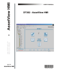
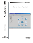
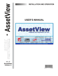
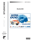
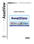
www.smar.com
Specifications and information are subject to change without notice.
Up-to-date address information is available on our website.
web: www.smar.com/contactus.asp
LD302 - AssetView HMI
LD302 - ASSETVIEW HMI
LD302 Home Page
This manual describes the pages developed for LD302 maintenance using AssetView.
The figure below shows the LD302 initial page and its options:
Figure 1. LD302 Home Page
The following sub-sections will describe each one of the pages developed for the device
maintenance.
3
User’s Manual
LD302 Identification Page
This page displays relevant information to the pressure transmitter. The user can easily identify and
specify the transmitter in the physical plant.
Figure 2. Identification Page
Device
TAG
Indicates the tag associated to the transmitter in the
physical plant. The tag can have up to 32 characters.
DEVICE TYPE
Identifies the transmitter type for a specific manufacturer.
DEVICE SERIAL NUMBER
Indicates the transmitter serial number.
DEVICE REVISION
Indicates the transmitter revision.
HARDWARE REVISION
Indicates the transmitter hardware revision.
DEVICE ID
Indicates the transmitter identification code. This code can
have up to 32 characters.
MANUFACTURER
Identifies the transmitter manufacturer.
MAIN BOARD SERIAL NUMBER
Indicates the serial number of the transmitter main board.
FIRMWARE REVISION
Indicates the transmitter firmware revision.
DD REVISION
Indicates the DD revision.
ORDERING CODE
Indicates the transmitter ordering code.
Sensor
4
SENSOR TYPE
Indicates the transmitter sensor type.
SENSOR FLUID
Indicates the fluid of the transmitter’s sensor.
SENSOR RANGE CODE
Indicates the range code of the transmitter’s sensor.
SENSOR ISOLATION MATERIAL
Indicates the sensor isolation material.
SENSOR SERIAL NUMBER
Indicates the transmitter sensor serial number.
LD302 - AssetView HMI
Flange
FLANGE TYPE
Indicates the flange type.
FLANGE MATERIAL
Indicates the flange material.
DRAIN/VENT MATERIAL
Indicates the drain/vent material.
O-RING MATERIAL
Indicates the o-ring material.
Remote Seal
NUMBER OF REMOTE SEALS
Indicates the number of remote seals.
REMOTE SEAL TYPE
Indicates the remote seal type.
REMOTE SEAL FLUID
Indicates the remote seal fluid.
REMOTE SEAL ISOLATION
MATERIAL
Indicates the remote seal isolation material.
LD302 Configuration Page
There are some parameters in the LD302 transducer block that can be used in the predictive and
proactive maintenance. It is possible to detect the performance decreasing by comparing the current
parameters with the standard values and then schedule the maintenance.
The user can check the general status diagnostic in the LD302 Diagnostic Page (refer to the next
section). This status is generated according to the user configuration in the LD302 Configuration
Page. For example, the “Sensor Failure“ diagnostic may be caused by an overpressure in the
sensor.
Figure 3. Configuration Page
5
User’s Manual
Device Operation Mode
Indicates the operation mode for the device:
OOS
If this mode is selected, the value of the Mode Block parameter will be Out of
Service for the Resource, Transducer and Analog Output blocks.
AUTO
If this mode is selected, the value of the Mode Block parameter will be Auto for the
Resource, Transducer, Display and Analog Output blocks.
MAN
If this mode is selected, the value of the Mode Block parameter will be Manual for
the Analog Output block, and Auto for the Resource, Transducer and Display
blocks.
Measured Type
Select the type of the measured variable:
LEVEL
Indicates the transmitter is measuring level.
PRESSURE
Indicates the transmitter is measuring pressure.
FLOW
Indicates the transmitter is measuring flow.
Measurement Configuration
AUTO ZERO
Enables and disables the zero cutoff.
CHARACTERIZATION
Enables and disables the pressure characterization curve.
FUNCTION
Indicates the function that acts in the Primary Value: Linear
or Table.
LOW CUT OFF
Indicates the value of the pressure cutoff. If the pressure
value is lower than the value indicated by Low Cut Off, zero
(“0”) will be displayed.
Engineering Variable
UNIT
Engineering unit.
0%
Value of the pressure corresponding to 0%, in EU.
100%
Value of the pressure corresponding to 100%, in EU.
Process Variable
UNIT
Unit of the process variable.
LOWER RANGE
Lower limit of the process variable.
UPPER RANGE
Upper limit of the process variable.
Alert Configuration
6
MAXIMUM OFFSET DEVIATION
Indicates the maximum offset deviation before an alarm is
generated.
OVERPRESSURE LIMIT
Defines the maximum overpressure limit before an alarm is
generated.
MAXIMUM GAIN DEVIATION
Defines the maximum gain before an alarm is generated.
MAXIMUM NUMBER OF
OVERPRESSURE
Defines the maximum number of overpressure before an
alarm is generated.
LD302 - AssetView HMI
LD302 Diagnostics Page
The user can check the general status diagnostic in the LD302 Diagnostic Page.
Figure 4. Diagnostic Page
Device Status
MAXIMUM PRESSURE
MEASURED
Indicates the maximum pressure measured.
MAXIMUM TEMPERATURE
MEASURED
Indicates the maximum temperature measured.
CURRENT OFFSET
Indicates the current calibrated offset.
CURRENT SPAN
Indicates the current calibrated span.
Diagnosis
This field shows the continuous diagnostic status for the device, including the function block
condition, the mechanical module condition and the sensor condition.
POWER UP
Indicates that the device has executed the initial operation
procedure.
SENSOR FAILURE
Indicates a failure in the sensor, such as overpressure.
MEMORY FAILURE
Indicates an electronic failure according to the internal
checking procedure, such as an incorrect checksum detected
in the main memory.
OUT OF SERVICE
Indicates that the function block is out of service.
DEVICE NEEDS MAINTENANCE
SOON
The internal diagnostic according to the user configuration or
device internal checking has detected that the device will
need maintenance soon. This diagnostic is related to
overpressure in the sensor.
DEVICE NEEDS MAINTENANCE
NOW
The internal diagnostic according to the user configuration or
device internal checking has detected that the device needs
maintenance. This diagnostic is related to the sensor
calibration.
CALIBRATION ERROR
Indicates that an error occurred during the device calibration,
or a calibration error has been detected while operating the
device.
7
User’s Manual
BLOCK CONFIGURATION
ERROR
Indicates that there is an error related to the XD_SCALE
parameter in the AI function block.
DATA INTEGRITY ERROR
Indicates that data stored in the system may be no longer
valid, for example, because the checksum of the data in the
RAM memory has failed when compared to the data in the
non-volatile memory.
SOFTWARE ERROR
The software has detected an error that may have been
caused by a deviation of a service routine, an interruption, a
lost pointer, etc.
ELECTRONICS FAILURE
An electronic component has failed.
GENERAL ERROR
A general error related to the device has been detected.
LD302 Calibration Page
This page displays configuration data used in the calibration procedures.
Figure 5. Calibration Page
Pressure Calibration Information
8
CALIBRATION UNIT
Indicates the unit for the pressure calibration procedure.
SENSOR LOWER RANGE LIMIT
Indicates the lower limit for the range’s sensor.
SENSOR UPPER RANGE LIMIT
Indicates the upper limit for the range’s sensor.
MINIMUM SPAN
Indicates the minimum value allowed between the lower
and upper points of the calibration.
CURRENT LOW POINT
CALIBRATION
Indicates the current lower point of the pressure
calibration.
LD302 - AssetView HMI
CURRENT HIGH POINT
CALIBRATION
Indicates the current higher point of the pressure
calibration.
FACTORY LOW POINT
CALIBRATION
Indicates the factory’s lower point of the pressure
calibration.
FACTORY HIGH POINT
CALIBRATION
Indicates the factory’s higher point of the pressure
calibration.
PRESSURE MEASURED
Indicates the pressure measured by the device.
TEMPERATURE MEASURED
Indicates the temperature measured by the device.
Temperature Calibration Information
CALIBRATION UNIT
Indicates the unit for the temperature calibration
procedure.
CALIBRATION TEMPERATURE
Indicates the value of the last temperature calibration.
Calibration Methods
NOTE
When the transmitter is installed, it is recommended to run the Lower Pressure Calibration
procedure to minimize the mounting. Please refer to the transmitter manual for further details.
LOWER PRESSURE CALIBRATION:
This method is used when calibrating the lower pressure point. The user can select the calibration
unit and type the value of the pressure applied as reference value to the transmitter, observing the
sensor limits and the minimum span.
When this method is selected, a message appears warning the user that this procedure must be
executed when the process stops or the plant control is set to manual.
Figure 6. Configuring the Mode Block
Click Yes, apply the pressure and wait for the sensor stabilization.
Figure 7. Stabilizing the Pressure
Click OK and the pressure measured will be shown.
Figure 8. Confirming the Value of the Pressure
9
User’s Manual
If the value is correct, click Yes to conclude this procedure. Otherwise, click No and type the
pressure value:
Figure 9. New Pressure Value
Click OK to apply the new pressure value, and then click Yes to confirm the alteration, as shown in
Figure 8. The calibration procedure will be concluded.
UPPER PRESSURE CALIBRATION:
This method is similar to the Lower Pressure Calibration procedure described above. It is used
when calibrating the pressure with the user’s reference instead of the manufacturer’s reference.
Figure 10. Configuring the Mode Block
Click Yes, apply the pressure, and wait for the sensor stabilization.
Figure 11. Stabilizing the Pressure
Click OK and the pressure measured will be shown.
Figure 12. Confirming the Value of the Pressure
If the value is correct, click Yes to conclude this procedure. Otherwise, click No, and type the
pressure value:
Figure 13. New Pressure Value
10
LD302 - AssetView HMI
Click OK to apply the new pressure value, and then click Yes to confirm the alteration, as shown in
Figure 12. The calibration procedure will be concluded.
SENSOR CHARACTERIZATION:
This method is used to correct the sensor reading in several points. Use an accurate and stable
pressure source to guarantee that the accuracy is at least three times better than the transmitter
accuracy.
Figure 14. Configuring the Mode Block
Click Next and wait for the pressure stabilization before performing the trim. The characteristic curve
of the sensor can be slightly nonlinear at a certain temperature and for some ranges. This nonlinearity can be corrected by the Characterization Trim. The user can characterize the transmitter
with the desired operating range to obtain a better accuracy. The characterization is determined
from two up to five points.
Apply the pressure to the transmitter and waits the sensor stabilization.
Figure 15. Configuring the First Point
The pressure measured will be shown. Type the first point value, and click Next Point.
Apply pressure to the second point click Next Point, and then, successively up to the last point. Up
to five points can be inserted. Click Finish to conclude the procedure.
NOTE
When more than two and less than five points are used, after insert them, and clicking Next
the following figure will appear. In the Curve Y (%) and Curve X (%) tabs only the calibrated
points will appear before clicking the Next option.
11
User’s Manual
Figure 16. Finishing the Points’ Configuration
Type the location when the Sensor Characterization procedure is executed, and click Submit.
Click Finish to conclude the procedure.
TEMPERATURE CALIBRATION
This method is used to calibrate the temperature sensor.
Figure 17. Stabilizing the Temperature
If the value is correct, click Next. Otherwise, type the correct temperature value, click Submit, wait
for the sensor stabilization, and then click Next. The following figure will appear.
12
LD302 - AssetView HMI
Figure 18. New Temperature Value
Type the location when the Temperature Calibration procedure is executed, and click Submit.
Click Finish to conclude the procedure.
LD302 Display Page
The user can save the data shown in the device's display.
Figure 19. Display Page
13
User’s Manual
Display
BLOCK TAG
Shows the tags list of the available instantiated blocks.
PARAMETER
Shows the list of available parameters to be displayed in the LCD
for the selected block in the Block Tag option.
SUB INDEX
Indicates the sub-index of the selected parameter.
MNEMONIC
Indicates the mnemonic of the selected parameter in the Parameter
option.
INC DEC
Indicates the value to be added or subtracted when acting the
parameter via local adjustment.
DECIMAL POINT NUMB
Indicates the number of digits after the decimal point that will be
shown in the LCD.
ACCESS
The user can select the access type of the selected parameter:
monitoring or action.
ALPHA NUM
Indicates if the alphanumeric field will be used for mnemonic or for
value.
LD302 Device View Page
The user can monitor the device's data opening the Device View page.
Figure 20. Device View Page
14