1
KATflow 100
Table of Contents
KATflow 100
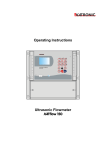
Operating Instructions
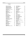
Table of Contents
Page
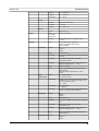
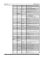
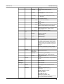
1 Safety instructions, legal requirements, warranty, return policy.................5
1.1 Symbols used in these operating instructions.............................................5
1.2 Safety instructions....................................................................................... 5
1.3 Warranty...................................................................................................... 6
1.4 Return policy............................................................................................... 6
1.5 Legislative requirements............................................................................. 6
2 Introduction...................................................................................................... 7
3 Installation........................................................................................................ 8
3.1 Unpacking and storage............................................................................... 8
3.1.1 Unpacking............................................................................................ 8
3.1.2 Storage ................................................................................................ 8
3.1.3 Identification of components................................................................. 8
3.2 Clamp-on sensor installation....................................................................... 9
3.3 Installation location...................................................................................... 9
3.4 Pipe preparation.......................................................................................... 12
3.5 Clamp-on sensor mounting configurations and separation distance...........12
3.6 Flowmeter installation.................................................................................. 13
3.6.1 Wall mounting....................................................................................... 13
3.6.2 Electrical connections........................................................................... 15
3.7 Clamp-on sensor mounting......................................................................... 16
3.7.1 Sensor pipe mounting configurations................................................... 16
3.7.2 Acoustic coupling gel............................................................................ 16
3.7.3 Correct positioning of the sensors........................................................ 17
3.7.4 Sensor mounting with tension straps.................................................... 17
4 Operation.......................................................................................................... 19
4.1 Switching On/Off......................................................................................... 19
4.2 Keypad and display..................................................................................... 19
4.2.1 Keypad key functions........................................................................... 19
4.2.2 Display functions.................................................................................. 21
4.3 Quick setup wizard...................................................................................... 22
4.4 Measurements............................................................................................. 25
4.4.1 Main process value (PV) display.......................................................... 25
4.4.2 Diagnostic displays............................................................................... 26
4.4.3 Totalisers.............................................................................................. 26
4.4.4 Datalogger............................................................................................ 26
5 Commissioning................................................................................................ 27
5.1 Menu structure............................................................................................ 27
5.2 Diagnostics.................................................................................................. 31
5.3 Display settings........................................................................................... 31
5.4 Output configuration.................................................................................... 33
5.4.1 Serial interface RS 232.........................................................................33
5.4.2 Serial interface RS 485.........................................................................33
5.4.3 HART output......................................................................................... 33
5.4.4 Analogue current output ...................................................................... 34
3