1
Installing and Operating Instructions
dIXEL
3.5
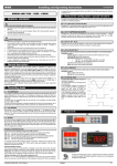
CONTROL OF CONDENSER FAN
The condenser fan relay is always activated except during defrost. During the defrost
the status of condenser fan depends on the cFE parameter:
with cFE= no the condenser fan doesn’t run during defrost
with cFE= yES the condenser fan runs during defrost
XW562K - V650 AND CX650
1
1598001822
GENERAL WARNING
4
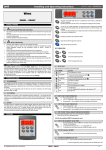
KEYBOARD
1.1
PLEASE READ BEFORE USING THIS MANUAL
•
This manual is part of the product and should be kept near the instrument for
easy and quick reference.
•
The instrument shall not be used for purposes different from those described
hereunder. It cannot be used as a safety device.
•
Check the application limits before proceeding.
1.2
•
•
•
•
•
•
•
•
2
SAFETY PRECAUTIONS
Check the supply voltage is correct before connecting the instrument.
Do not expose to water or moisture: use the controller only within the operating
limits avoiding sudden temperature changes with high atmospheric humidity to
prevent formation of condensation
Warning: disconnect all electrical connections before any kind of maintenance.
Fit the probe where it is not accessible by the End User. The instrument must not
be opened.
In case of failure or faulty operation send the instrument back to the distributor or
to “Dixell S.p.A.” (see address) with a detailed description of the fault.
Consider the maximum current which can be applied to each relay (see
Technical Data).
Ensure that the wires for probes, loads and the power supply are separated and
far enough from each other, without crossing or intertwining.
In case of applications in industrial environments, the use of mains filters (our
mod. FT1) in parallel with inductive loads could be useful.
To display and modify target set point; in programming mode it selects a
parameter or confirms an operation.
By pressing it when the current time is displayed, it allows the User to reset the current time and three holidays.
GENERAL DESCRIPTION
The XW562K series is fitted with a Real Time Clock which allows programming of up
to eight daily defrost cycles, divided into holidays and workdays.
Model XW562K, 127x123 mm format, is microprocessor based controller suitable for
applications on medium or low temperature refrigerating units. It is provided with six
relay outputs to control 2 compressors, defrost - which can be either electrical or hot
gas - the evaporator fans, the condenser fan and the alarm output. They are also
provided with 3 NTC probe inputs, one for temperature control, the other 2 to control
the defrost end temperature of the evaporators. There are 3 digital inputs (free
contact) for the door switch, the pressure switch and for safety end of defrost.
The electronic controller can work with two parameter lists, switch over by a key.
The standard TTL output allows the user to connect, by means of a TTL/RS485
external module, a ModBUS-RTU compatible monitoring system and to programme
the parameter list with the “Hot Key”.
The controller also provides an output for remote keyboard V650 or CX650.
3
In programming mode it browses the parameter codes or increases the
displayed value.
in programming mode it browses the parameter codes or decreases the
displayed value.
By holding it pressed for 3s the current time is displayed and it permits
the User to enter, Defrost and Clock parameter menu.
By holding it pressed for 3s the defrost is started. The manual defrost
overrides the minimum running time of a compressor (“on” parameter)
By pressing it when the current time is displayed, it allows the User to
set defrost times.
Prg1 Keep it pressed for 2 seconds to switch the controller from the
Program 2 to the Program 1.
CONTROLLING LOADS
3.1
THE COMPRESSORS
The regulation is performed according to the temperature measured by the thermostat
probe with a positive differential from the set point: if the temperature increases and
reaches set point plus differential the compressor is started. The compressor is turned
off when the temperature reaches the set point value again.
In case of fault in the thermostat probe the start and stop of the compressor are timed
through parameters “COn” and “COF”.
Prg2 Keep it pressed for 2 seconds to switch the controller from the
Program 1 to the Program 2.
KEY COMBINATIONS
ND
3.2
2 COMPRESSOR MANAGEMENT
The relay of the second compressor is activated in parallel with the relay of the first
compressor, with a possible delay set in the AC1 or AC2 parameters, depending on
program 1 or 2. Both the compressors are switched off at the same time.
3.3
DEFROST
2 defrost modes are available through the “tdF” parameter: defrost with electrical
heater or hot gas. The defrost interval is control by means the real time clock,
depending on the hours set in the parameters Ld1..Ld8 on workdays and in
Sd1…Sd8 in holidays for program 1, 2L1.. 2L8 on workdays and in 2S1…2S8 in
holidays for program 2.
At the end of defrost the drip time is controlled through the “Fdt” parameter.
4.1
1598001822 XW562K LND GB R3.0 10.11.2007.doc
XW562K
To lock and unlock the keyboard.
+
To enter the programming mode.
+
To exit the programming mode.
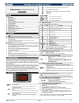
USE OF LEDS
Each LED function is described in the following table.
LED
3.4
CONTROL OF EVAPORATOR FANS
The fan control mode is selected by means of the “FnC” parameter for program 1 and
Fn2” parameter for program 2:
C-n fans will switch ON and OFF with the compressor and not run during defrost;
C-y fans will switch ON and OFF with the compressor, also during defrost
After defrost, there is a timed fan delay allowing for drip time, set by means of the
“Fnd” parameter.
O-n fans will run continuously and not run during defrost;
O-y fans will run continuously also during defrost
An additional parameter “FSt” provides the setting of temperature, detected by the
evaporator probe, above which the fans are always OFF. This can be used to make
sure circulation of air only if his temperature is lower than set in “FSt”.
+
MODE
ON
FLASHING
ON
FLASHING
ON
FLASHING
ON
ON
ON
Function
The compressor 1 is running
- Programming Phase (flashing with )
- Anti-short cycle delay enabled
The defrost is enabled
Programming Phase (flashing with
)
Drip time in progress
The evaporator fan is running
The evaporator fan delay after defrost is running
The compressor 2 is running
The second compressor delay is running
Alarm is happening
Condenser fan is running
Prg1 is running
ON
Prg2 is running
ON
FLASHING
***
*
1/6
Installing and Operating Instructions
dIXEL
3.
4.
Function of the LEDs placed on the left top side of buttons (V650):
BUTTON
Prg1
Prg2
MODE
ON
ON
To revert to the normal working push for some seconds the SET key.
6
HOW TO SEE AND MODIFY THE SET POINT
1.
Push for 2sec the SET key: the display will show the Set point
value;
2.
To change the Set value push the o or n arrows within 10s.
3.
To memorise the new set point value push the SET key again or
wait 10s.
4.3
TO START A MANUAL DEFROST
Push the DEF key for more than 2 seconds and a manual defrost will start.
Manually defrost has higher priority than min. compressor running time (onparameter).
4.4
TO ENTER IN PARAMETERS LIST
To enter the parameter list (user accessible parameters) operate as follows:
1. Enter the Programming mode by pressing the Set and
DOWN key for 5s (Pr2 appears)
2. Release the keys
and
start blinking
3. Select the required parameter.
4. Press the “SET” key to display its value .
5. Use “UP” or “DOWN” to change its value.
6. Press “SET” to store the new value and move to the following parameter.
To exit: Press SET + UP or wait 30s without pressing a key.
NOTE: the set value is stored even when the procedure is exited by waiting the timeout to expire.
4.5
HOW TO CHANGE THE PARAMETER VALUE
1. Enter the Programming mode.
2. Select the required parameter with o or n.
3. Press the “SET” key to display its value (
and
LED starts blinking).
4. Use o or n to change its value.
5. Press “SET” to store the new value and move to the following parameter.
To exit: Press SET + UP or wait 15s without pressing a key.
NOTE: the new programming is stored even when the procedure is exited by waiting
the time-out.
HOW TO LOCK THE KEYBOARD
1. Keep the o and n keys pressed together for more than 3 s the o and n
keys.
2. The “POF” message will be displayed and the keyboard is locked. At
this point it is only possible the viewing of the set point or the MAX o
Min temperature stored and to switch ON and OFF the light, the
auxiliary output and the instrument.
TO UNLOCK THE KEYBOARD
Keep the o and n keys pressed together for more than 3s.
4.7
1.
2.
3.
4.
5.
5
TO SEE THE PROBE VALUES
Enter in “Pr2” level.
Select “Prd” parameter with o or n.
Press the “SET” key to display “Pb1” label alternate with Pb1 value.
Use o and n keys to display the other probe values.
Press “SET” to move to the following parameter.
5.1
TO SEE AND SET THE CURRENT TIME AND DAY
1. Push the DOWN key for more than 3 seconds
2. The following messages are displayed in sequence:
Hur (hour) followed by the hour;
Min (Minute) followed by the minutes
dAY (day) followed by the day of the week
3. By pushing the SET key, the setting of current hour, minutes, day will
be possible
4. To exit: push SET+ UP key or wait 15 seconds
5.2
TO SET THE DEFROST TIMES
5.3
1.
2.
Td = SEt + dot + dHy
Td = (SEt + dot) + {[( Tm – SEt ) x dHy ] / Hy }
where Tm = temperature measured by room probe
Td = temperature displayed by the controller
DEFROST
MdF enabling the defrost key: yES= defrost key enabled;
no = defrost key disabled.
tdF Defrost type: rE = electrical heater (Compressor OFF)
in = hot gas (Compressor and defrost relays ON)
EdF Defrost mode:
rtc = Real Time Clock mode. Defrost time follows Ld1÷Ld8 parameters on
workdays and Sd1÷Sd8 on holidays for program 1, 2L1÷2L8 parameters on
workdays and 2S1÷2S8 on holidays for program 1
in = interval mode. The defrost starts when the time “Idf” is expired.
dtE Defrost termination temperature fro program 1: (-50,0÷110,0°C; -58÷230°F)
(Enabled only when the evaporator probe is present) sets the temperature
measured by the evaporator probe which causes the end of defrost.
dt2 Defrost termination temperature fro program 2: (-50,0÷110,0°C; -58÷230°F)
(Enabled only when the evaporator probe is present) sets the temperature
measured by the evaporator probe which causes the end of defrost.
IdF Interval between defrosts for program 1: (1÷120h) It is used as safety time in
case of RTC problem. Determines the time interval between the beginning of two
defrost cycles, when the RTC is broken.
Id2 Interval between defrosts for program 2: (1÷120h) It is used as safety time in
case of RTC problem. Determines the time interval between the beginning of two
defrost cycles, when the RTC is broken.
Mtd (Maximum) duration of defrost for program 1: (0÷255 min) When P2P = n, no
evaporator probe, it sets the defrost duration, when P2P = y, defrost end based
on temperature, it sets the maximum length for defrost.
Push the DOWN key for more than 3 seconds
The current time is displayed as written above
By pushing DEF key, the setting defrost time will be possible.
To exit, press SET + UP or wait 15s without pressing any key.
STAND BY FUNCTION
Enter the programming.
Select the onF parameter
1598001822 XW562K LND GB R3.0 10.11.2007.doc
PARAMETER LIST
REGULATION
Set1
Set point 1 (LS÷US) Is the target set point 1
Set2
Set point 2 (LS2÷US2) Is the target set point 2
Hy Differential for the set1: (0,1÷25,5°C; 1÷45°F): Intervention differential for set
point1, always positive. Compressor Cut IN is Set Point Plus Differential (Hy).
Compressor Cut OUT is when the temperature reaches the set point.
Hy2 Differential for the set2: (0,1÷25,5°C; 1÷45°F): Intervention differential for set
point2, always positive. Compressor Cut IN is Set Point Plus Differential (Hy).
Compressor Cut OUT is when the temperature reaches the set point.
LS Minimum set point 1 limit: (-50,0°C÷SET1; -58°F÷SET1) Sets the minimum
acceptable value for the set point1.
US Maximum set point 1 limit: (SET1÷110°C; SET1÷230°F) Set the maximum
acceptable value for set point1.
LS2 Minimum set point 2 limit: (-50,0°C÷SET2; -58°F÷SET2) Sets the minimum
acceptable value for the set point2.
US2 Maximum set point 2 limit: (SET2÷110°C; SET2÷230°F) Set the maximum
acceptable value for set point2.
odS Outputs activation delay at start up: (0÷255 min) This function is enabled at
the initial start up of the instrument and inhibits any output activation for the
period of time set in the parameter. (AUX and Light can work)
AC Anti-short cycle delay: (0÷30 min) interval between the compressor stop and
the following restart.
AC1 2nd compressor delay at start up, program 1 (0÷255sec) Time interval
between the switching on of the first compressor and the second one.
nd
AC2 2 compressor delay at start up, program 2 (0÷255sec) Time interval
between the switching on of the first compressor and the second one.
on minimum compressor running time (0÷30min)
Mon Maximum compressor running time (0÷120min, with 0 the function is
disabled) If this time is reached the compressor is switched off for the Ac time,
then if there are the conditions it restarts.
cP2 Second compressor enabled with program 2 (yES, no)
Con Compressor ON time with faulty probe: (0÷255 min) time during which the
compressor is active in case of faulty thermostat probe. With COn=0 compressor
is always OFF.
COF Compressor OFF time with faulty probe: (0÷255 min) time during which the
compressor is off in case of faulty thermostat probe. With COF=0 compressor is
always active.
S2E Second program enabled: no=the second set point is disabled and not
selectable; yES = the second set point can be selected.
DISPLAY
CF Temperature measurement unit: °C = Celsius; °F = Fahrenheit . When the
measurement unit is changed the SET point and the values of the regulation
parameters have to be modified
rES Resolution (for °C): (in = 1°C; de = 0,1°C) allows decimal point display.
dE = 0,1°C; in = 1 °C
dot Display offset for program 1: (0÷25.5 °C) it is used for the special visualisation
LINDE’s algorithm.
do2 Display offset for program 2: (0÷25.5 °C) it is used for the special visualisation
LINDE’s algorithm.
dHy Display histeresys: (0÷25.5 °C) it is used for the special visualisation LINDE’s
algorithm.
When the temperature measured by the room probe is less then
Setpoint + Hysteresis, the displayed temperature must be calculated by the
microprocessor according to the following formula:
if Tm > SEt + Hy ->
if Tm ≤ SEt + Hy ->
REAL TIME CLOCK FUNCTIONS
1.
2.
3.
4.
Change its value from “no” to “yES”.
Exit the programming and the instrument will be palced in stanby mode.
FUNCTION
Prg1 is running
Prg2 is running
4.2
4.6
1598001822
XW562K
2/6
Installing and Operating Instructions
Mt2 (Maximum) duration of defrost for program 2: (0÷255 min) When P2P = n, no
evaporator probe, it sets the defrost duration, when P2P = y, defrost end based
on temperature, it sets the maximum length for defrost.
dFd Display during defrost: dEF = “dEF” label;
dEG = “dEG” label;
dSd Start defrost delay:(0÷59min) This is useful when different defrost start times
are necessary to avoid overloading the plant.
Fdt Drain down time: (0÷60 min.) time interval between reaching defrost termination
temperature and the restoring of the control’s normal operation. This time allows
the evaporator to eliminate water drops that might have formed due to defrost.
dPO First defrost after start-up: y = Immediately; n = after the IdF time
cFE Condenser fan working during defrost : no = condenser fan doesn‘t run
during defrost; yES = condenser fan runs during defrost
EVAPORATOR FANS
FnC Fan operating mode for program 1:
C-n = running with the compressor, OFF during the defrost;
C-y = running with the compressor, ON during the defrost;
O-n = continuous mode, OFF during the defrost;
O-y = continuous mode, ON during the defrost;
FC2 Fan operating mode for program 2:
C-n = running with the compressor, OFF during the defrost;
C-y = running with the compressor, ON during the defrost;
O-n = continuous mode, OFF during the defrost;
O-y = continuous mode, ON during the defrost;
Fnd Fan delay after defrost: (0÷255 min) The time interval between the defrost end
and evaporator fans start.
FSt Fan stop temperature: (-50÷110°C; -58÷230°F) setting of temperature, detected
by evaporator probe, above which the fan is always OFF.
ALARMS
ALU High temperature alarm setting related to the SET1: (-50 ÷ 150°C) when this
temperature is reached and after the ALd delay time the tAL alarm is enabled.
Au2 High temperature alarm setting related to the SET2: (-50 ÷ 150°C) when this
temperature is reached and after the ALd delay time the tAL alarm is enabled.
ALd Temperature alarm delay: (0÷255 min) time interval between the detection of
an alarm condition and the corresponding alarm signalling.
dAO Exclusion of temperature alarm at start-up or after a defrost: (from 0.0 min
to 23.5h) time interval between the detection of the temperature alarm condition
after instrument power on and alarm signalling.
tbA Alarm relay muting: (no = muting disabled: the alarm relay is active till the alarm
condition lasts, yES = muting enabled: the alarm relay can be muting by pressing
a key.
oAP Alarm relay polarity: CL = contact 63-64 are closed when an alarm happens.
oP = contact 63-65 are closed when an alarm happens.
ArE Alarm relay activated by first digital input (door switch):
(no = the digital input doesn’t activate the alarm relay; yES = the digital input
activates the alarm relay)
PROBE INPUTS
Ot Thermostat probe calibration: (-12.0÷12.0°C/ -21÷21°F) allows to adjust
possible offset of the thermostat probe.
P2P Evaporator probe presence: no= not present: the defrost stops only by time;
yES= present: the defrost stops by temperature and time.
OE Evaporator probe calibration: (-12.0÷12.0°C/ -21÷21°F) allows to adjust
possible offsets of the evaporator probe.
P3P Second evaporator probe presence: no= not present: the defrost stops only by
time; yES= present: the defrost stops by temperature and time.
O3 Second Evaporator probe calibration: (-12.0÷12.0°C/ -21÷21°F) allows to
adjust possible offsets of the evaporator probe.
DIGITAL INPUTS
i1P Door switch input polarity: CL : the digital input is activated by closing the
contact; OP : the digital input is activated by opening the contact.
i2P Pressure switch digital input polarity:
CL : the digital input is activated by closing the contact;
OP : the digital input is activated by opening the contact
i3P Digital input polarity of the safety thermostat for defrost:
CL : the digital input is activated by closing the contact;
OP : the digital input is activated by opening the contact
did Time interval delay for the first digital input (door switch):(0÷255 min.) “did”
parameter defines the time delay between the detection and the successive
signalling of the alarm at first digital input.
N.B. : To disable a defrost cycle set it to “nu”(not used).
Ex. If Ld6=nu ; the sixth defrost cycle is disabled
2L1÷2L8 Workday defrost start for program 2 (0 ÷ 23h 50 min.) These parameters
set the beginning of the eight programmable defrost cycles during workdays. Ex.
When 2L2 = 12.4 the second defrost starts at 12.40 during workdays.
2S1÷2S8 Holiday defrost start for program 2 (0 ÷ 23h 50 min.) These parameters
set the beginning of the eight programmable defrost cycles on holidays. Ex.
When 2S2 = 3.4 the second defrost starts at 3.40 on holidays.
OTHER
Adr RS485 serial address (1÷247): Identifies the instrument address when
connected to a ModBUS compatible monitoring system.
onF To put in stand by the instrument: no= instrument is working. yES =
instrument is placed in standby mode.
NOTE1: changing this parameter the instrument is placed in STANDBY mode
when the programming is exited.
***NOTE: to revert the instrument from stand by the standard working press
for some seconds the SET key.****
rEL Release software: (read only) Software version of the microprocessor.
Ptb Parameter table: (read only) it shows the original code of the dIXEL parameter
map.
Prd Probes display: (read only) display the temperature values of the evaporator
probe Pb2 and the auxiliary probe Pb3.
7
1598001822 XW562K LND GB R3.0 10.11.2007.doc
XW562K
DIGITAL INPUTS
The XW562K can support 3 free contact digital inputs.
The function of each one are described below.
7.1
DOOR SWITCH (TERMINALS 69-70)
The digital input should be activated by closing the contact. The external alarm can be
delayed by means of the did parameter.
The recovery of this alarm type on the display is „EA“. By means of the ArE parameter
can be chosen, either if there is the message „EA“ on the display and the alarm relay
is activated or if there is only the message „EA“ on the display.
The alarm condition disappears as soon as the digital input is open.
The polarity of this digital input is set in the i1P parameter.
7.2
PRESSURE SWITCH INPUT (TERMINALS 68-71)
When the pressure switch is activated the compressors are immediately stopped and
the “PAL” message is displayed. The alarm relay is always activated.
Condenser fans and evaporator fans continue working.
If the pressure switch is activated during a hot gas defrost, the defrost is stopped.
Standard regulation will restart 6min after the end of High pressure switch alarm.
The polarity of this digital input is set in the i2P parameter.
7.3
SAFETY THERMOSTAT FOR DEFROST (TERMINALS 67-72)
When this digital input is activated, the controller finishes the defrost immediately and
goes to cooling operation.
The safety thermostat alarm is excluded for the dAo time when the instrument is
switched on.
The “dEA” alarm message is displayed and the alarm relay is activated.
The next defrost starts at the next programmed defrost time, if the digital input is deactivated.
The polarity of this digital input is set in the i3P parameter.
8
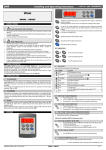
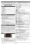
INSTALLATION AND MOUNTING
Keyboard V650 shall be mounted on vertical panel, in a 72x56 mm hole, and fixed
using screws ∅ 3 x 2mm. To obtain an IP65 protection grade use the front panel
rubber gasket (mod. RGW-V).
Keyboard CX650 shall be mounted on vertical panel, in a 29x71 mm hole, and fixed
using the special bracket supplied.
Power module XW562K shall be mounted in a panel with two or more screws and it
must be connected to the keyboard by means of a two-wire cable (∅ 1mm). The
temperature range allowed for correct operation is 0 - 60 °C. Avoid places subject to
strong vibrations, corrosive gases, excessive dirt or humidity. The same
recommendations apply to probes. Let the air circulate by the cooling holes.
8.1 V650: CUT OUT
TO SET CURRENT TIME AND WEEKLY HOLIDAYS (3SEC.
afterward
)
Hur Current hour (0 ÷ 23 h)
Min Current minute (0 ÷ 59min)
dAY Current day (Sun ÷ SAt)
Hd1 First weekly holiday (Sun ÷ nu) Set the first day of the week which follows the
holiday times.
Hd2 Second weekly holiday (Sun ÷ nu) Set the second day of the week which
follows the holiday times.
Hd3 Third weekly holiday (Sun ÷ nu) Set the third day of the week which follows
the holiday times.
N.B. Hd1,Hd2,Hd3 can be set also as “nu” value (Not Used)
afterward
)
TO SET DEFROST TIMES (3SEC.
Ld1÷Ld8 Workday defrost start for program 1 (0 ÷ 23h 50 min.) These parameters
set the beginning of the eight programmable defrost cycles during workdays. Ex.
When Ld2 = 12.4 the second defrost starts at 12.40 during workdays.
Sd1÷Sd8 Holiday defrost start for program 1 (0 ÷ 23h 50 min.) These parameters
set the beginning of the eight programmable defrost cycles on holidays. Ex.
When Sd2 = 3.4 the second defrost starts at 3.40 on holidays.
1598001822
83,5
56
72
dIXEL
40
9
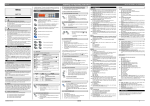
ELECTRICAL CONNECTIONS
The instruments are provided with screw terminal block to connect cables with a cross
section up to 2,5 mm2 for the digital and analogue inputs. Relays and power supply
3/6
Installing and Operating Instructions
dIXEL
have a Faston connection (6,3mm). Heat-resistant cables have to be used. Before
connecting cables make sure the power supply complies with the instrument’s
requirements. Separate the probe cables from the power supply cables, from the
outputs and the power connections. Do not exceed the maximum current allowed on
each relay, in case of heavier loads use a suitable external relay.
N.B. Maximum current allowed for all the loads is 20A.
9.1
PROBE CONNECTIONS
The probes shall be mounted with the bulb upwards to prevent damages due to
casual liquid infiltration. It is recommended to place the thermostat probe away from
air streams to correctly measure the average room temperature. Place the defrost
termination probe among the evaporator fins in the coldest place, where most ice is
formed, far from heaters or from the warmest place during defrost, to prevent
premature defrost termination.
10
TTL SERIAL LINE
The TTL connector allows, by means of the external module TTL/RS485, to connect
the unit to a network line ModBUS-RTU compatible as the dIXEL monitoring system
XJ500 (Version 3.0). The same TTL connector is used to upload and download the
parameter list of the “HOT KEY“. These instruments can be ordered with direct serial
output RS485 (Optional).
11
USE OF THE PROGRAMMING “HOT KEY “
The Wing units can UPLOAD or DOWNLOAD the parameter list from its own E2
internal memory to the “Hot Key” and vice-versa.
11.1
DOWNLOAD (FROM THE “HOT KEY” TO THE INSTRUMENT)
1.
Turn OFF the instrument by means of the ON/OFF key, remove the TTL serial
cable if present, insert the “Hot Key” and then turn the Wing ON.
2.
Automatically the parameter list of the “Hot Key” is downloaded into the Wing
memory, the “DoL” message is blinking. After 10 seconds the instrument will
restart working with the new parameters.
3.
Turn OFF the instrument remove the “Hot Key”, plug in the TTL serial cable,
then turn it ON again.
At the end of the data transfer phase the instrument displays the following messages:
“end “ for right programming. The instrument starts regularly with the new
programming.
“err” for failed programming. In this case turn the unit off and then on if you want to
restart the download again or remove the “Hot key” to abort the operation.
11.2
UPLOAD (FROM THE INSTRUMENT TO THE “HOT KEY”)
1.
Turn OFF the instrument by means of the ON/OFF key and remove the TTL
serial cable if present; then turn it ON again.
When the Wing unit is ON, insert the “Hot key” and push o key; the "uPL"
message appears.
3.
Push “SET” key to start the UPLOAD; the “uPL” message is blinking.
4.
Turn OFF the instrument remove the “Hot Key”, plug in the TTL serial cable,
then turn it ON again.
At the end of the data transfer phase the instrument displays the following messages:
“end “ for right programming.
“err” for failed programming. In this case push “SET” key if you want to restart the
programming again or remove the not programmed “Hot key”.
2.
12
ALARM SIGNALS
Message Cause
“P1”
Thermostat probe failure
“P2”
“P3”
“tAL”
“EA”
“PAL”
“dEA”
„COO“
„DEF“
„POF“*
“rtc”
Evaporator probe failure
Second evaporator probe
failure
Max. temperature alarm
Digital input 1 activated:
external alarm
Pressure switch alarm
Safety thermostat for
defrost alarm
Cooling down
Defrost is running
Keyboard locked
Real time clock alarm
Outputs
Alarm output ON; Compressor output
according to parameters “COn” and “COF”
Alarm output ON; Defrost ended by time
Alarm output ON; Defrost ended by time
Alarm output ON; Other outputs unchanged
Alarm relay depends on the ArE par.
Output unchanged.
Compressors off
Alarm relay on
Defrost stopped. Alarm relay on. Start cooling
1598001822
12.2
ALARM RECOVERY
Probe alarms : “P1” (probe1 faulty), “P2” and “P3” automatically stop 10s after the
probe restarts normal operation. Check connections before replacing the probe.
Temperature alarms “tAL” automatically stop as soon as the thermostat temperature
returns to normal values.
Temperature alarm “tAL” automatically stops as soon as the thermostat temperature
returns to normal values and when defrost is started.
Alarms “EA”, “PAL” and “dEA” recover as soon as the digital input is disabled.
13
TECHNICAL DATA
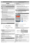
V650 keyboard
Housing: self extinguishing ABS.
Case: V650 facia 64x164 mm; depth 23mm
Mounting:
V650: panel mounting in a 56x72 mm panel cut-out with two screws. ∅ 3x2mm.
Distance between the holes 40mm
Protection: IP20; Frontal protection: IP65
Power supply: from XW562K power module
Display: 3 digits, red LED, 14,2 mm high;
Optional output: buzzer
CX650 keyboard
Housing: self extinguishing ABS.
Case: CX650 facia 35x77 mm; depth 23mm
Mounting: panel mounting in a 29x71 mm panel cut-out
Protection: IP20; Frontal protection: IP65
Power supply: from XW562K power module
Display: 3 digits, red LED, 14,2 mm high;
Optional output: buzzer
XW562K main board
Housing: self extinguishing ABS.
Mounting: by screw
Protection: IP20.
Frontal protection: IP65 with frontal gasket mod RG-L. (optional)
2
Connections: Screw terminal block ≤ 2,5 mm heat-resistant wiring and tab terminal
6,3x0,8mm for load and supply and tab terminal 6,3x0,8mm for digital inputs and
probes
Power supply: 230Vac or. 110Vac ± 10%
Rated impulsive voltage: 2500V
Overvoltage Category: II
Power absorption: 7VA max.
Inputs: 3 NTC probes
Digital inputs: 2 free voltage
Relay outputs: Total current on loads MAX. 20A
compressor 1&2 : relay SPST 20(8) A, 250Vac
evaporator fans: relay SPST 8(3) A, 250Vac
defrost: relay SPST 8A, 250Vac
alarm: SPDT relay 8(3) A, 250Vac
condenser fans: SPST relay 8(3) A, 250Vac
Serial output : TTL standard
Communication protocol: Modbus - RTU
Data storing: on the non-volatile memory (EEPROM).
Kind of action: 1B.
Pollution degree: 2
Software class: A.
Operating temperature: 0÷50 °C.
Storage temperature: -25÷60 °C.
Relative humidity: 20÷85% (no condensing)
Measuring and regulation range: NTC probe: -40÷110°C (-58÷230°F)
ADDITIONAL INFORMATION, FURNISHED BY MANUFACTURER
Frontal protection: IP65 with frontal gasket mod RGW-V. (optional)
Accuracy (ambient temp. 25°C): ±0,5 °C ±1 digit
Internal clock back-up: 5 years
Resolution: 0,1 °C or 1°C or 1 °F (selectable).
Alarm output ON; Other outputs unchanged;
Defrosts according to par. “IdF”
To erase the alarm enter the Clock setting
menu by pushing the DOWN key for few
second, see. par. 5.2
The alarm message is displayed until the alarm condition is recovery.
All the alarm messages are showed alternatively.
12.1
SILENCING BUZZER / ALARM RELAY OUTPUT
If “tbA = yES”, once the alarm signal is detected the buzzer and the relay are is
silenced by pressing any key.
If “tbA = no”, only the buzzer is silenced while the alarm relay is on until the alarm
condition recovers.
1598001822 XW562K LND GB R3.0 10.11.2007.doc
XW562K
4/6
dIXEL
14
Installing and Operating Instructions
DIMENSIONS
Label
rES
dot
do2
dHy
Name
Resolution (integer/decimal point)
Display offset, program 1
Display offset, program 2
Display histeresys
DEFROST
MdF Defrost key enabling
tdF
EdF
dtE
dt2
Defrost type
Kind of defrost
Defrost termination temperature (1°Evaporator)
Defrost termination temperature for program 2
IdF
id2
Mtd
Mt2
dFd
dSd
Fdt
dPO
15
16
Interval between defrost cycles
Interval between defrost cycles for the program 2
(Maximum) length for 1° defrost
(Maximum) length of defrost for the program 2
Display during defrost
Defrost delay
Draining time
First defrost after start up
FANS
CFE Condenser fan working during defrost
FnC Fans operating mode
Fc2 Fans operating mode with program 2
Fnd Fans delay after defrost
FSt Fans stop temperature
ALARMS
ALU MAXIMUM temperature alarm for set1
Au2 MAXIMUM temperature alarm for set2
ALd Temperature alarm delay
dAO Delay of temperature alarm at start up
tBA Alarm relay silencing
oAP Alarm relay polarity
ArE Digital input 1 actives the alarm relay
ANALOGUE INPUTS
Ot
Thermostat probe calibration
P2P Evaporator probe presence
OE Evaporator probe calibration
P3P Second evaporator probe presence
O3 Second evaporator probe calibration
DIGITAL INPUTS
I1P Door switch polarity
I2P Pressure switch digital input polarity
I3P Defrost end digital input polarity
dId Digital input alarm delay
CONNECTIONS
Label Name
TIME AND WEEKLY HOLIDAYS
Hur
Current hour
Min
Current minute
dAY
Current day
Hd1
First weekly holiday
Hd2
Second weekly holiday
Hd3
Third weekly holiday
DEFROST TIMES
st
Ld1
1 workdays defrost start
Ld2
2nd workdays defrost start
Ld3
3rd workdays defrost start
th
Ld4
4 workdays defrost start
Ld5
5th workdays defrost start
Ld6
6th workdays defrost start
Ld7
7th workdays defrost start
th
Ld8
8 workdays defrost start
Sd1
1st holiday defrost start
nd
Sd2
2 holiday defrost start
rd
Sd3
3 holiday defrost start
Sd4
4th holiday defrost start
th
Sd5
5 holiday defrost start
Sd6
6th holiday defrost start
Sd7
7th holiday defrost start
th
Sd8
8 holiday defrost start
2L1
1st workdays defrost start program 2
2L2
2nd workdays defrost start program 2
2L3
3rd workdays defrost start program 2
2L4
4th workdays defrost start program 2
2L5
5th workdays defrost start program 2
2L6
6th workdays defrost start program 2
2L7
7th workdays defrost start program 2
2L8
8th workdays defrost start program 2
2S1
1st holiday defrost start program 2
2S2
2nd holiday defrost start program 2
2S3
3rd holiday defrost start program 2
2S4
4th holiday defrost start program 2
DEFAULT SETTING VALUES
Label Name
REGULATION
Set1 Set point1
Set2 Set point2
Hy
Differential for set1
Hy2 Differential for set2
LS
Minimum set point1
US Maximum set point1
LS2 Minimum set point2
US2 Maximum set point2
OdS Outputs activation delay at start up
AC Anti-short cycle delay
AC1 Second compressor start delay
Ac2 Second compressor start delay progr.2
on
Minimum time a compressor remains on (it’s used both
for compr. 1 and 2)
Mon Maximum time compressor is continuously on
(permanent run monitoring)
cP2 Compressor 2 enabled with program 2
COn Compressor ON time with faulty probe
COF Compressor OFF time with faulty probe
S2F Second set point enabling
DISPLAY
CF Temperature measurement unit
1598001822 XW562K LND GB R3.0 10.11.2007.doc
Range
Default
LS÷US
LS2÷US2
0,1÷25,5 °C
0,1÷25,5 °C
-50,0°C÷SET1
SET1 ÷ 110°C
-50,0°C÷SET2
SET2 ÷ 110°C
0÷255 min.
0÷30 min.
0÷255s
0 ÷ 255s
0÷30 minutes
40,0
40,0
2,0
2,0
-40,0
50,0
-40,0
60,0
0
3
10
10
5
0÷120min
0
y = yES; n = no
0÷255 min.
0÷255 min.
yES÷no
yES
15
30
yES
°C ÷ °F
°C
XW562K
1598001822
Range
in ÷ dE
0÷25.5 °C
0÷25.5 °C
0÷25.5 °C
Default
dE
2.0
2.0
2.0
yES= enabled
no= disabled
rE, in
rtc, in
-50,0÷110°C
-50.0°C o –58°F ÷ 110°C o
230°F
1÷120h
1 ÷ 120 hours
0÷255 min.
0 ÷ 255 minuts
dEG; dEF
0÷255min
0÷60 min.
n÷y
YES
yES÷no
C-n, C-y, O-n, O-y
c_n / c_Y / o_n / o_Y
0÷255 min.
-50,0÷110°C
YES
o-n
o-n
0
2.0
-50,0÷110°C
-50,0÷110°C
0÷255 min.
0 ÷ 23h 50 min.
yES÷no
oP, cL
yES÷no
50.0
50.0
15
1,3
no
oP
no
-12,0÷12,0°C
no ÷ yES
-12,0÷12,0°C
no ÷ yES
-12,0÷12,0°C
0.0
yES
0.0
no
0.0
CL÷OP
CL÷OP
CL÷OP
0÷255 min.
cL
oP
oP
0
Range
Default
0 ÷ 23
0 ÷ 59
Sun ÷ SAt
Sun÷ SAt – nu
Sun÷ SAt – nu
Sun÷ SAt – nu
------nu
nu
nu
0 ÷ 23h 50 min. - nu
0 ÷ 23h 50 min. - nu
0 ÷ 23h 50 min. - nu
0 ÷ 23h 50 min. - nu
0 ÷ 23h 50 min. - nu
0 ÷ 23h 50 min. - nu
0 ÷ 23h 50 min. - nu
0 ÷ 23h 50 min. - nu
0 ÷ 23h 50 min. - nu
0 ÷ 23h 50 min. - nu
0 ÷ 23h 50 min. - nu
0 ÷ 23h 50 min. - nu
0 ÷ 23h 50 min. - nu
0 ÷ 23h 50 min. - nu
0 ÷ 23h 50 min. - nu
0 ÷ 23h 50 min. - nu
0 ÷ 23h 50 min. - nu
0 ÷ 23h 50 min. - nu
0 ÷ 23h 50 min. - nu
0 ÷ 23h 50 min. - nu
0 ÷ 23h 50 min. - nu
0 ÷ 23h 50 min. - nu
0 ÷ 23h 50 min. - nu
0 ÷ 23h 50 min. - nu
0 ÷ 23h 50 min. - nu
0 ÷ 23h 50 min. - nu
0 ÷ 23h 50 min. - nu
0 ÷ 23h 50 min. - nu
3,0
nu
nu
nu
nu
nu
nu
nu
nu
nu
nu
nu
nu
nu
nu
nu
7,0
19,0
nu
nu
nu
nu
nu
nu
nu
nu
nu
nu
rE
rtc
8,0
8,0
12
12
30
30
dEF
0
0
no
5/6
dIXEL
Label
2S5
2S6
2S7
2S8
Adr
onF
rEL
Ptb
Prd
Installing and Operating Instructions
Name
5th holiday defrost start program 2
6th holiday defrost start program 2
7th holiday defrost start program 2
8th holiday defrost start program 2
OTHER
Serial address
Switch off the controller
Software release
Map code
Probe display
1598001822
Range
Default
0 ÷ 23h 50 min. - nu
nu
0 ÷ 23h 50 min. - nu
nu
0 ÷ 23h 50 min. - nu
nu
0 ÷ 23h 50 min. - nu
nu
0÷247
no/yES
-------
1
no
6.2
1
Dixell S.p.A.. Via dell’Industria, 27 - 32010 Z.I Pieve d’Alpago (BL) ITALY
tel. +39 - 0437 - 98 33 - fax +39 - 0437 - 98 93 13
E-mail:[email protected] - http://www.dixell.com
1598001822 XW562K LND GB R3.0 10.11.2007.doc
XW562K
6/6