1
Installing and Operating Instructions
Mt2 (Maximum) duration of defrost for program 2: (0÷255 min) When P2P = n, no
evaporator probe, it sets the defrost duration, when P2P = y, defrost end based
on temperature, it sets the maximum length for defrost.
dFd Display during defrost: dEF = “dEF” label;
dEG = “dEG” label;
dSd Start defrost delay:(0÷59min) This is useful when different defrost start times
are necessary to avoid overloading the plant.
Fdt Drain down time: (0÷60 min.) time interval between reaching defrost termination
temperature and the restoring of the control’s normal operation. This time allows
the evaporator to eliminate water drops that might have formed due to defrost.
dPO First defrost after start-up: y = Immediately; n = after the IdF time
cFE Condenser fan working during defrost : no = condenser fan doesn‘t run
during defrost; yES = condenser fan runs during defrost
EVAPORATOR FANS
FnC Fan operating mode for program 1:
C-n = running with the compressor, OFF during the defrost;
C-y = running with the compressor, ON during the defrost;
O-n = continuous mode, OFF during the defrost;
O-y = continuous mode, ON during the defrost;
FC2 Fan operating mode for program 2:
C-n = running with the compressor, OFF during the defrost;
C-y = running with the compressor, ON during the defrost;
O-n = continuous mode, OFF during the defrost;
O-y = continuous mode, ON during the defrost;
Fnd Fan delay after defrost: (0÷255 min) The time interval between the defrost end
and evaporator fans start.
FSt Fan stop temperature: (-50÷110°C; -58÷230°F) setting of temperature, detected
by evaporator probe, above which the fan is always OFF.
ALARMS
ALU High temperature alarm setting related to the SET1: (-50 ÷ 150°C) when this
temperature is reached and after the ALd delay time the tAL alarm is enabled.
Au2 High temperature alarm setting related to the SET2: (-50 ÷ 150°C) when this
temperature is reached and after the ALd delay time the tAL alarm is enabled.
ALd Temperature alarm delay: (0÷255 min) time interval between the detection of
an alarm condition and the corresponding alarm signalling.
dAO Exclusion of temperature alarm at start-up or after a defrost: (from 0.0 min
to 23.5h) time interval between the detection of the temperature alarm condition
after instrument power on and alarm signalling.
tbA Alarm relay muting: (no = muting disabled: the alarm relay is active till the alarm
condition lasts, yES = muting enabled: the alarm relay can be muting by pressing
a key.
oAP Alarm relay polarity: CL = contact 63-64 are closed when an alarm happens.
oP = contact 63-65 are closed when an alarm happens.
ArE Alarm relay activated by first digital input (door switch):
(no = the digital input doesn’t activate the alarm relay; yES = the digital input
activates the alarm relay)
PROBE INPUTS
Ot Thermostat probe calibration: (-12.0÷12.0°C/ -21÷21°F) allows to adjust
possible offset of the thermostat probe.
P2P Evaporator probe presence: no= not present: the defrost stops only by time;
yES= present: the defrost stops by temperature and time.
OE Evaporator probe calibration: (-12.0÷12.0°C/ -21÷21°F) allows to adjust
possible offsets of the evaporator probe.
P3P Second evaporator probe presence: no= not present: the defrost stops only by
time; yES= present: the defrost stops by temperature and time.
O3 Second Evaporator probe calibration: (-12.0÷12.0°C/ -21÷21°F) allows to
adjust possible offsets of the evaporator probe.
DIGITAL INPUTS
i1P Door switch input polarity: CL : the digital input is activated by closing the
contact; OP : the digital input is activated by opening the contact.
i2P Pressure switch digital input polarity:
CL : the digital input is activated by closing the contact;
OP : the digital input is activated by opening the contact
i3P Digital input polarity of the safety thermostat for defrost:
CL : the digital input is activated by closing the contact;
OP : the digital input is activated by opening the contact
did Time interval delay for the first digital input (door switch):(0÷255 min.) “did”
parameter defines the time delay between the detection and the successive
signalling of the alarm at first digital input.
N.B. : To disable a defrost cycle set it to “nu”(not used).
Ex. If Ld6=nu ; the sixth defrost cycle is disabled
2L1÷2L8 Workday defrost start for program 2 (0 ÷ 23h 50 min.) These parameters
set the beginning of the eight programmable defrost cycles during workdays. Ex.
When 2L2 = 12.4 the second defrost starts at 12.40 during workdays.
2S1÷2S8 Holiday defrost start for program 2 (0 ÷ 23h 50 min.) These parameters
set the beginning of the eight programmable defrost cycles on holidays. Ex.
When 2S2 = 3.4 the second defrost starts at 3.40 on holidays.
OTHER
Adr RS485 serial address (1÷247): Identifies the instrument address when
connected to a ModBUS compatible monitoring system.
onF To put in stand by the instrument: no= instrument is working. yES =
instrument is placed in standby mode.
NOTE1: changing this parameter the instrument is placed in STANDBY mode
when the programming is exited.
***NOTE: to revert the instrument from stand by the standard working press
for some seconds the SET key.****
rEL Release software: (read only) Software version of the microprocessor.
Ptb Parameter table: (read only) it shows the original code of the dIXEL parameter
map.
Prd Probes display: (read only) display the temperature values of the evaporator
probe Pb2 and the auxiliary probe Pb3.
7
1598001822 XW562K LND GB R3.0 10.11.2007.doc
XW562K
DIGITAL INPUTS
The XW562K can support 3 free contact digital inputs.
The function of each one are described below.
7.1
DOOR SWITCH (TERMINALS 69-70)
The digital input should be activated by closing the contact. The external alarm can be
delayed by means of the did parameter.
The recovery of this alarm type on the display is „EA“. By means of the ArE parameter
can be chosen, either if there is the message „EA“ on the display and the alarm relay
is activated or if there is only the message „EA“ on the display.
The alarm condition disappears as soon as the digital input is open.
The polarity of this digital input is set in the i1P parameter.
7.2
PRESSURE SWITCH INPUT (TERMINALS 68-71)
When the pressure switch is activated the compressors are immediately stopped and
the “PAL” message is displayed. The alarm relay is always activated.
Condenser fans and evaporator fans continue working.
If the pressure switch is activated during a hot gas defrost, the defrost is stopped.
Standard regulation will restart 6min after the end of High pressure switch alarm.
The polarity of this digital input is set in the i2P parameter.
7.3
SAFETY THERMOSTAT FOR DEFROST (TERMINALS 67-72)
When this digital input is activated, the controller finishes the defrost immediately and
goes to cooling operation.
The safety thermostat alarm is excluded for the dAo time when the instrument is
switched on.
The “dEA” alarm message is displayed and the alarm relay is activated.
The next defrost starts at the next programmed defrost time, if the digital input is deactivated.
The polarity of this digital input is set in the i3P parameter.
8
INSTALLATION AND MOUNTING
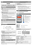
Keyboard V650 shall be mounted on vertical panel, in a 72x56 mm hole, and fixed
using screws ∅ 3 x 2mm. To obtain an IP65 protection grade use the front panel
rubber gasket (mod. RGW-V).
Keyboard CX650 shall be mounted on vertical panel, in a 29x71 mm hole, and fixed
using the special bracket supplied.
Power module XW562K shall be mounted in a panel with two or more screws and it
must be connected to the keyboard by means of a two-wire cable (∅ 1mm). The
temperature range allowed for correct operation is 0 - 60 °C. Avoid places subject to
strong vibrations, corrosive gases, excessive dirt or humidity. The same
recommendations apply to probes. Let the air circulate by the cooling holes.
8.1 V650: CUT OUT
TO SET CURRENT TIME AND WEEKLY HOLIDAYS (3SEC.
afterward
)
Hur Current hour (0 ÷ 23 h)
Min Current minute (0 ÷ 59min)
dAY Current day (Sun ÷ SAt)
Hd1 First weekly holiday (Sun ÷ nu) Set the first day of the week which follows the
holiday times.
Hd2 Second weekly holiday (Sun ÷ nu) Set the second day of the week which
follows the holiday times.
Hd3 Third weekly holiday (Sun ÷ nu) Set the third day of the week which follows
the holiday times.
N.B. Hd1,Hd2,Hd3 can be set also as “nu” value (Not Used)
afterward
)
TO SET DEFROST TIMES (3SEC.
Ld1÷Ld8 Workday defrost start for program 1 (0 ÷ 23h 50 min.) These parameters
set the beginning of the eight programmable defrost cycles during workdays. Ex.
When Ld2 = 12.4 the second defrost starts at 12.40 during workdays.
Sd1÷Sd8 Holiday defrost start for program 1 (0 ÷ 23h 50 min.) These parameters
set the beginning of the eight programmable defrost cycles on holidays. Ex.
When Sd2 = 3.4 the second defrost starts at 3.40 on holidays.
1598001822
83,5
56
72
dIXEL
40
9
ELECTRICAL CONNECTIONS
The instruments are provided with screw terminal block to connect cables with a cross
section up to 2,5 mm2 for the digital and analogue inputs. Relays and power supply
3/6