1
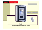
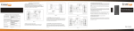
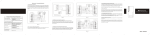
Installation Manual INTEGRATED ACCESS CONTROLLER KZ-500-U/H VERSION 1.0 Integrated Access Controller – Installation manual CONTENTS 1. Introduction …………..…………..…………..…………..…………..……………….. 3 2. Features …………..…………..…………..…………..…….…...…………..……….. 4 3. Specifications …………..…………..…………..…………..……………..………….. 5 4. Controller installation …………..…………..…………..…………..…………….. 5 5. Controller wiring diagram …………..…………….………………..……………. 6 6. Detailed Programming Guide …………..………………...………………..… AAT Holding sp. z o.o. Wszelkie prawa zastrzeżone. 8 2 Integrated Access Controller – Installation manual 1. Introduction KZ-500-U/H Integrated access controller The KZ-500-U/H is fully waterproof stand alone Proximity access Reader, which uses advanced microprocessor, equipped with large capacity Flash memory, supports up to10000 cards. It can read both 125KHZ HID card and 125KHZ EM card. It is so easy to add or delete card users by using the master card; besides, with infrared remote control programmer, the user can set the reader by themselves. The KZ-500-U/H not only has the features of low power consumption, automatic selection of lock ,anti vandal alarm and exit button, but also has the protective functions against input over voltage and outputs short-circuit. The block enrollment function makes it can enroll maximum 10,000pcs HID cards or EM cards at a time within 10 minutes. These features make the KZ-500-U/H easy in operation, safe and reliable; it is an idea choice for door access. AAT Holding sp. z o.o. Wszelkie prawa zastrzeżone. 3 Integrated Access Controller – Installation manual Features Standalone controller with built in Card Reader Waterproof, confirm to IP68 Use capacity: 10,000 Card interface: HID&EM 125KHZ card/tag Remote control for programming With Manager cards for fast add and delete users Card block enrollment Can enroll maximum 10,000pcs cards at a time within 10 minutes Wiegand 26 input/output Can be used as salve reader 2 pcs of KZ-500 can be interconnected Can be used as controller by connection Wiegand reader Anti-passback function Alarm signal output, Door open detection LED display Full of 10000 users, recognizing speed <15ms. AAT Holding sp. z o.o. Wszelkie prawa zastrzeżone. 4 Integrated Access Controller – Installation manual Specifications Supply Voltage User capacity Sleeping Current Card type Card Reading Distance DC12V±10% 10,000 <15mA HID&EM 125khz Card/Tag 4~8cm Wiegand 26 -25~60℃ Wiegand interface Operating Temperature Operating Humidity Environment Lock output load Alarm output load Adjustable Door Relay Time Adjustable Alarm Time Wiring Connections Manager card Dimensions 20%~98% Confirm to IP68 Max20A Max20A 00-99 seconds 0- 3 minutes Electric Lock, Exit Button, DOTL, External Alarm Two 103*48*23mm Installation Drill holes on the wall or prepare the cassette. Wire through the hole, and blanket the unused cable in case of short circuit. Fix the back cover firmly on the cassette or the wall. Attach the reader to the back cover. AAT Holding sp. z o.o. Wszelkie prawa zastrzeżone. 5 Integrated Access Controller – Installation manual Wiring No 1 Color Green Function Description D0 Wiegand output, input signal wire D0 2 White D1 Wiegand output, input signal wire D1 3 Grey ALARM+ connecting to the negative pole of the alarm equipment 4 Yellow OPEN To connect to one part of Exit Button 5 Brown D_IN Door Contact input, 6 Red 12V (+) 12Vdc Positive Regulated Power Input 7 Black GND (-) Negative Regulated Power Input 8 Blue VSS the negative pole of the controller, connect to the other part of Exit button and door contact L- Connect to the negative pole of the Lock 9 10 Purple Orange L+/ Alarm+ Connect to the positive pole of the lock and alarm equipment Connection Diagram Note: Do not power on until all wiring has been completed AAT Holding sp. z o.o. Wszelkie prawa zastrzeżone. 6 Integrated Access Controller – Installation manual To Reset to Factory Default Power off, use the supplied Contact Pin to short out the 2P socket on the main board, then power on, if successful, the beeper will beep twice, the LED shines in orange, remove the Short Pin, then read the Two Manager cards (Manager add card firstly, Manager delete card secondly), after that the LED turns in red, means reset to factory default setting successfully. Remarks: Reset to factory default setting, the users' information enrolled is still retained. When Re-set to Factory setting, the two Manager cards must be re-enrolled. Sound and Light indication Operation status LED Reset to factory default setting Orange Sleeping mode Red shines slow Operation successful Buzzer Two short ring Short ring Enter into programming mode Red shines Short ring Enter into setting Orange shines Short ring Exist from programming mode Red shines slow Short ring Operation failed Three short ring Open the door Green shines Short ring Alarm Red shines fast Alarm AAT Holding sp. z o.o. Wszelkie prawa zastrzeżone. 7 Integrated Access Controller – Installation manual Detailed Programming Guide User settings There are 2 ways to add and delete users: A - By manager card; B - By remote control A - By Manager card (The most convenient way) To Add user by Manager Add Card To Delete User by Manager Delete Card Manager add card Read card Manager add card Cards can be added continuously. Manager delete card Read Card Manager delete card Cards can be deleted continuously. B- By Remote control Enter into the programming mode firstly To Enter the programming mode * Manager Password # 888888 is the default factory master code Remarks: All the steps below must be done after enter into programming mode To change the master code To add a card user (Method 1) This is the faster way to enter cards using ID number auto generation. The card can be either be presented or input the 8 digit card number from the card can be manually entered To add a card user (Method 2) This is the alternative way to enter cards using User ID Allocation. In this method a User ID is allocated to a card. Only one user ID can be allocated to a single card. 0 New Password # Repeat New Password # The master code must be 6~8 digit number. 1 Read Card # or 1 Input Card number (8 digit) # Card can be added continuously without exiting programming mode. The card number is the last 8 digits of the number printing on the card. 1 ID number # Read Card # or 1 ID number # the Card number (8 digits) # To add a series cards users – Block Enrollment 8 ID number # 8 digits Card number # Card quantity # (It can enroll maximum 10,000pcs cards at a time within 10 minutes.) Card quantity is between 1-10,000. Of the 8 digits card number, for HID card, they are the 3 digits of a facility code and 5 digits of a serial number; for EM card, they are the last 8 digits on the card. 2 Read Card # or 2 Card number # To delete a card user. Note users can be deleted continuously without exiting programming mode To delete ALL users. (Note: This option will delete all users but Manager Cards. Be careful with use) 2 0000 # AAT Holding sp. z o.o. Wszelkie prawa zastrzeżone. 8 Integrated Access Controller – Installation manual Door setting Lock power setting Fail secure (Unlocked when power on) This is the factory default, 3 seconds. Fail safe (unlocked when power is off) 4 0~99 # 0-99 is to set the door relay time 0-99 seconds. 5 0~99 # 0-99 is to set the door relay time 0-99 seconds. Anti-submarine Settings Anti-submarine Disabled (Factory default) Anti-submarine Master Mode: 3 0 # Anti-submarine Auxiliary Machinery Mode 3 1 # (Note: the detailed wiring diagram and illus3 2 # trate ,please refer to “Advanced application” Door open detection Door Open Too Long (DOTL) warning. When used with an optional magnetic contact or built-in magnetic contact of the lock, if the door is opened normally, but not closed after 1 minute, the inside buzzer will beep automatically to remind people to close the door and continue for 1 minute before switching off automatically. Door Forced Open warning. When used with an optional magnetic contact or built in magnetic contact of the lock, if the door is forced open, or if the door is opened after 120 seconds of the electro-mechanical lock not closed properly, the inside buzzer and alarm output will both operate. To disable door open detection. 6 0 # (Factory default) To enable door open detection 6 1 # Security Mode Setting Reader Lockout & Alarm Output options. If there are 10 invalid cards or 10 incorrect PIN numbers in a 10 minute period either the reader will lockout for 10 minutes or the alarm will operate for 10 minutes, depending on the option selected below. Normal status (No lockout or Alarm) 7 0 # (Factory default setting) Keypad Lockout 7 1 # Alarm Output 7 2 # LED Control LED disabled 7 3 # LED enabled 7 4 # Alarm output time To set the alarm output time (0-3 minutes) Factory default is 1 minute 9 0~3 # To remove the alarm To remove the Door Forced Open warning Read valid card or Master Code# To remove the Door Open Too Long warning Close the door or Read valid card or Master Code # To Unlock the door To Unlock the door Read User card (Note that Manager Card can’t be used as User Card to unlock the door.) AAT Holding sp. z o.o. Wszelkie prawa zastrzeżone. 9 Integrated Access Controller – Installation manual Advanced Application KZ-500 operating as a Controller In this mode the KZ-500 supports a Wiegand 26 bit input so an external Wiegand device with a 26 bit output can be connected to the Wiegand input terminals. Cards are required to be added at the external reader, except where an external ID reader is used, in this case cards can be added at either reader or controller. See figure 1. KZ-500-U/H c Two KZ-500 units interconnected for a single door In this mode two KZ-500 units are used for a single door, one for entry and the other for exit. Either device acts as the controller and reader at the same time. Users can be enrolled on either of the devices. In this mode the user capacity for one door can be up to 20000. The setting of the two KZ-500 units must be the same including the master code. See figure 2. KZ-500-U/H #1 KZ-500-U/H #2 Figure 2. AAT Holding sp. z o.o. Wszelkie prawa zastrzeżone. 10 Integrated Access Controller – Installation manual Anti-passback function for single door (3 1 #) The connection diagram is as figure 1. Install one Wiegand reader (or a KZ-500 without user information as reader) outside the door, connecting to one KZ-500 Controller inside the door, which acts as the Anti-passback Master unit. Of the two devices, they build up an anti-passback system for single door. The operation and function is as below: 4.1 Set the needed function and enroll the User Cards on the inside KZ-500 Antipassback Master unit. 4.2 With the valid user card, the user can only enter the door from the outside reader, and exit from the inside KZ-500 Controller. On the other hand, without entering record from the reader, the user can’t exit from the controller inside, also, the user can’t enter in and exit twice continuously. Anti-passback function for 2 doors The connection diagram is as Figure 3. Door 1 with one KZ-500 , and Door 2 with one KZ-500, set one KZ-500 on Door 1 as the Anti-passback Auxiliary unit (3 2 #), and set the other KZ-500 on Door 2 as the Anti-passback Master unit (3 1 #). Then they build up a two doors anti-passback system, which is normally used for parking lot…etc The operation and function is as below: 5.1 Set the needed function and enroll the User Cards from KZ-500 - Antipassback Master unit on Door 2. 5.2 With the valid user card, the user can only enter in from Door 1, and exit from Door 2. On the other hand, without entering record from the Auxiliary unit, the user can’t exit from the Master unit or Auxiliary unit, also, the user can’t enter in and exit twice continuously. Controller KZ500 #2 Controller KZ500 #1 Figure 3. AAT Holding sp. z o.o. Wszelkie prawa zastrzeżone. 11 AAT Holding sp. z o.o. ul. Puławska 431, 02-801 Warszawa tel. 22 546 05 46, faks 22 546 05 01 e-mail: [email protected], www.aat.pl Warszawa