1
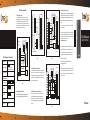
Attachment: Advanced Application 1.SR-2400 operating as a Controller In this mode the SR-2400 supports a Wiegand 26 bit input so an external Wiegand device with a 26 bit output can be connected to the Wiegand input terminals on the CFX-SR-2400 Either an ID card reader (125 KHZ) or an IC card reader (13.56MHZ) can be connected to the CrosFox. Cards are required to be added at the external reader, except where an externalEM reader is used, in this case cards can be added at either reader or controller. See figure 1 Reliable. Durable. Affordable J1 Green D0 D1 White D1 +12V GND Power SR-2400 controller J1 D0 Green D1 White ALARM- SR-2400 Quick reference Programming Guide Function description Choose from the relevant function below and input Enter the programming mode * 888888 # then you can do the programming (888888 is the default factory master code) To exit the programming mode OPEN Yellow Brown +12V Red GND Black VSS Blue L- L+ ALARM+ * wiegand reader GND +12V DC12V/3A + Em card Ic card HID card - D0 0 New code # Repeat New code # (Code must be 6-8 digit numbers.) ALARM- D1 OPEN ALARM- Brown D_IN +12V Black GND Blue VSS + Purple - Orange Green White - Grey + Delete card user OPEN D_IN Red Red +12V GND Black Black GND VSS Blue Blue VSS Purple L- Orange L+ ALARM+ Brown +12V L- L+ ALARM+ Alarm door detecting switch Exit button Purple - Orange + Lock SR-2400 controller 2 SR-2400 controller 1 figure 3 figure 2 Alarm 5.1 Set the needed function and enroll the User Cards on the inside SR-2400 Anti-submarine Master unit. 5.2 With the valid user card, the user can only enter the door from the outside reader, and exit from the inside SR-2400 Controller.Onthe other hand, without entering record from the reader,the user can't exit fromthecontroller inside, also,the user can'tenter in twice without the first exit record, and vice versa. Anti-submarine function for 2 doors SR-2400,and Door 2 with one, The connection diagram is as Figure 4. Door 1 with one SR-2400 set one SR-2400 on Door 1 as the Anti-submarine Auxiliary(3 2 unit # ), and set the other SR-2400 on Door 2 as the Anti-submarine Master unit (3 1 #). They build up a anti-submarine system, which is normally used for parking lot......etc. CFX-SR-2400 Waterproof Standalone Proximity Reader The operation and function is as below: 6.1 Set the needed function and enroll the User Cards from SR-2400 Anti-submarine Master unit on Door 2. door detecting switch Exit button Purple - Orange Lock + 3. Two CFX-SR-2400 units interconnected for a single door , In this mode two SR-2400 units are us for a single,door one for entry and the other for exit. Either device acts as the controller and reader at the same time. Users can be enrolled in either of the devices. In this mode the user capacity for one door can be up to 20000. The setting of the two SR-2400 units must be the same including the same including the master code.See figure 3 2.SR-2400 operating isa Wiegand Output Reader In this mode the SR-2400 supports a Wiegand 26 bit Output so the Wiegand data lines can be connected to any controller which supports a Wiegand 26 bit input. Seefigure 2 4. Two CFX-SR-2400 units interconnected & interlocked for 2 doors two doors I n t h i s m o d e t w o S R - 2 4 0 0 u n i t s a r e u s e d f o r t w o d o o r s which are then interconnected and interlocked.In this mode the doors canbe interlocked so that when door 1 is open,door 2 cannot be opened, and vice versaThe interlocked function is mainly prisons,and other places where a higher levelof securityis required. SR-2400 controller 2 SR-2400 controller 1 Power J1 D0 Green D1 White ALARM- OPEN Figure 1 To Unlock the door To Unlock the door ALARM- Reliable. Durable. Affordable + ( Can add card continuously) 2 Read Card # Grey - 1 Read Card # ( Can delete card continuously) D0 D1 Brown Yellow DC12V/3A Door 1 Grey Brown +12V Red - + - + + Yellow D_IN Door 2 - Alarm 2 Alarm 1 door detecting switch 1 Add card user Green White Yellow OPEN D_IN L- L+ ALARM+ Controller with wiegand 26 input reader p lug Note: that to undertake the following programming the master user must enter into the programming mode Change the master code Grey J1 - + D1 Grey D_IN Powerful supply D0 outdoor DC12V/3A J1 Yellow Red Controller Power Indoor D0 5. Anti-submarine function for single door (3 1 #) The connection diagram is as figure 1. Install one Wiegand reader (or a SR-2400 without user information as reader) outside the door,connecting to one SR-24000 Controller , inside the door,which acts as the Anti-submarine Master unit. of the two devices, they build up an anti-submarine system for single door.The operation and function is as below: Exit button 2 Exit button 1 J1 Green D0 White D1 Grey ALARM- Yellow OPEN Brown D_IN Red +12V door detecting switch 2 GND Black Black GND VSS Blue Blue VSS - Purple L- + Orange L+ ALARM+ L- L+ ALARM+ Purple - Orange + Lock 1 Lock 2 6.2 With the valid user card, the user can only enter in from Door 1, and exit from Door 2. On the other hand, without entering record from the Auxiliary unit, the user can't exit from the Master unit or Auxiliary unit , also, the user can't enter in twice without the first exit record, and vice versa. User manual See figure 4 Read user card figure 4 .6. .7. .8. .9. .10. 1. Packing List Name Specification Quantity SR-2400 1 Standalone Proximity Reader Infrared remote control 1 Manager card One for add, one for delete Short Pin Used for factory default setting 1 SR-2400 1 Self Tapping Screws 3.5*27mm 4/2 ALARM- A C Please ensure that all the above contents are correct. If any are missing, please notify the supplier of the SR-2400. The SR-2400 is fully waterproof standalone Proximity access Reader which uses advanced , microprocessor, equipped with large capacity Flash memory,supports up to 10,000 cards. It is so easy to add or delete card users by using the master card, besides, with Infrared remote control programmerthe user can set the features by themselves, including Alarm, Self-protection, , interlock and Anti-submarine back Function. In additional, with infrared remotecontrol interlock and Anti-submarine back Function. In additional, with infrared remote. 61mm 95.5mm 2. Description Shielded cables The SR-2400 not only has the features of low power consumption, automatic selection of lock anti vandal alarm and exit button, ut also has the protective functionsagainst input over voltage and outputs short-circuit.These features make the SR-2400,reliablend easy in operation. It is an ideal choice for door access. D 6. Wiring No Color Function Description D0 White D1 Wiegand output, input signal wire D1 3 Grey ALARM+ connecting to the negative pole of the alarm equipment 4 Yellow OPEN To connect to one part of Exit Button Brown D_IN Door Contact input 6 Red 12V (+) 12Vdc Positive Regulated Power Input <15mA Humidity 20% 98% 7 Black GND (-) Negative Regulated Power Input 125KHZ EM card Lock output load Max20A 8 Blue VSS Alarm output load Max20A the negative pole of the controller, connect to the other part of Exit button and door contact 10cm Wiegand interface Wiegand 26 Manager card Two User capacity 10,000 Dimensions 103 x 48 x 23mm .1. Red I/O Q6 R8 Q2 To Delete User by Manager Card R20 R19 Figure 1 Black Purple - Orange To Enter the programming mode NOTE:The above diagrams show the output interface circuits. Unlike most lock and alarm outputs which use a relay that can be shocked or magnetized,the SR-2400 uses MOS outputs for both the Lock Output on the left and the Alarm Output on theright. Blue 9 Purple L- 10 Orange L+/Alarm+ D0 Green Lock + D1 White ALARM- Power off, use the supplied Contact Pin to short out the 2P socket on the mainboard, then power on, if successful, the beeper will beep twice, the LED shines in orange, remove the Short Pin, then read any two EM cards, after that the LED turns in red, means reset to factory default setting successfully. of the two EM cards read, the first one is Manager add card, the second one is Manager delete card. Yellow D_IN Brown +12V Red GND Black VSS Blue L+ ALARM+ Alarm + - Orange Special Power Supply Connect to the negative pole of the Lock Connect to the positive pole of the lock and alarm equipment .2. PUSH NC COM NO Remarks: Reset to factory default setting, the users' information enrolled is still retained. When reset to Factory default setting, the two Manager cards must be re-enrolled. To change the master code To add a card user (Method 1) To add a card user(Method 2) Do not power on until all wiring has been completed .3. To delete a card user To delete ALL users. ( Note: This option will delete all users but 9. Sound and Light indication door detecting switch Purple Manager add card Read user card Manager add card Cards can be added continuously. Manager delete card Read user card Manager Delete ca rd Cards can be deleted continuously. * Manager Password # 888888 is the default factory master code Remarks: All the steps below must be done after entering into programming mode DC12V/3A Grey OPEN L- Exit button To Add user by Manager Card B- By Remote control Fail-securelock Green 2 5 Card Reading Distance 5 L- R7 Fail-safe lock 1 Wiegand output, input signal wire D0 60 Card type A - By Manager card(The most convenient way) ALARM- door detecting switch 40mm -20 Sleeping Current - J1 Can be used as salve reader 2 pcsW can be interconnected/ interlocked Can be used as controller by connecting slave reader Anti-submarine back Function Alarm signal output,Door open detection Full of 10,000 users, recognizing speed <15ms. 10% + + There are 2 ways to add and delete users: A - By manager card;; B - By remote control L+ D6 8.To Reset to Factory Default and Manager Card setting Temperature DC12V L+ ALARM+ 3. Features 4. Specifications Supply Voltage Brown L- 4-low level 5-high level DC12V/3A when alarm, the I/O outputs high level. +12V I/O D_IN VSS B By programme setting, I/O switch between low level and high level. Grey Yellow GND Alarm - White OPEN +12V Exit button Green 10.1 User settings Alarm Interface Principle: Lock Interface Principle: Common Power Supply J1 D1 10. SR-2400 Detailed Programming Guide 7. Interface Circuits SR-2400 D0 2 User manual Standalone Card Reader User capacity: 10,000 Card interface: 125KHZ EM Card Remote control for programming With Manager cards for fast add and delete users Wiegand 26 input/output Connection Diagram 5. Installation Drill holes on the wall or prepare the cassette. Wire through the hole,and blanket the unused cable in case of short circuit. Fix the back cover firmly on the cassette or the wall. Attach the reader to the back cover. 0 New Password # Repeat New Password # The master code must be 6 8 digit number. 1 Read Card # Card can be added continuously without exiting programming mode. LED Buzzer Reset to factory default setting Orange Two short ring Sleeping mode Red shines slow Short ring Operation successful 2 Read Card # or 2 Card number (8 digit) # 2 0000 # Exist from programming mode Red shines slow Short ring 4 0 99 # 0-99 is to set the door relay time 0-99 seconds. Fail safe (unlocked when power is off) 5 0 99 # 0-99 is to set the door relay time 0-99 seconds. .4. 6 1 # Security Mode Setting Reader Lockout & Alarm Output options. If there are 10 invalid cards within 1 0 mi nut es, the Reader will lockout for 10 minutes or the alarm will operate for 10 minutes, depending on the option selected below. Normal status (No lockout or alarm) 7 0 # (Factory default setting) Door Interlock. Door interlock disabled 8 0 # Door interlock enabled 8 1 # Alarm output time To remove the door forced open warning Fail secure (Unlocked when power on) This is the factory default, 3 seconds: Alarm To enable door open detection 9 0~3 # To remove the alarm 10.2 Door setting Short ring Red shines fast 6 0 # To set the alarm output time (0-3 minutes) Factory default is 1 minute Orange shines Alarm To disable door open detection. (Factory default) 7 2 # Enter into setting Short ring Door open detection Door Open Too Long (DOTL) warning. When used with an optional magnetic contact or built-in magnetic contact of the lock, if the door is opened normally, but not closed after 1 minute, the inside buzzer will beep automatically to remind people to close the door and continue for 1 minute before switching off automatically. Door Forced Open warning. When used with an optional magnetic contact or built in magnetic contact of the lock, if the door is forced open, or if the door is opened after 120 seconds of the electro-mechanical lock not closed properly, the inside buzzer and alarm output will both operate. Alarm Output Lock Power Setting Three short ring 3 2 # The card number is the last 8 digits of the number printing on the card. Short ring Green shines Antisubmarine A uxiliary M ode (Factory default) ( Note: the detailed wiring diagram and illustration, please refer to the Advanced application ) . 7 1 # Red shines Open the door 3 1 # Reader Lockout Enter into programming mode Operation failed 3 0 # Anti-submarine Master Mode 1 Input Card number (8 digit) # Manager Cards. Be careful with use) Operation status Anti-submarine Disabled Anti-submarine Settings .5. To remove the door open too long warning Read valid card or Master Code # Close the door or Read valid card or Master Code # To Unlock the door To Unlock the door Read user card Note:that Manager Card can't be used to unlock the door. .6.