1
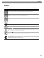
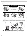
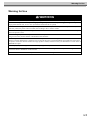
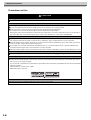
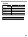
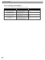
COLOR INKJET PRINTER JV5-320S OPTION DOUBLE SIDED PRINTING OPERATION MANUAL MIMAKI ENGINEERING CO., LTD. TKB Gotenyama Building, 5-9-41, Kitashinagawa, Shinagawa-ku, Tokyo 141-0001, Japan Phone : +81-3-5420-8671 Fax : +81-3-5420-8687 URL : http://www.mimaki.co.jp/ D201828-11 Foreword Congratulations on your purchase of MIMAKI color ink jet printer, JV5-320S with double sided printing function. With this optional function of JV5-320S, double sided printing with solvent ink (4-color and 6-color) is available. CAUTION DISCLAIMER OF WARRANTY THIS LIMITED WARRANTY OF MIMAKI SHALL BE THE SOLE AND EXCLUSIVE WARRANTY AND IS IN LIEU OF ALL OTHER WARRANTIES, EXPRESS OR IMPLIED, INCLUDING, BUT NOT LIMITED TO, ANY IMPLIED WARRANTY OF MERCHANTABILITY OR FITNESS, AND MIMAKI NEITHER ASSUMES NOR AUTHORIZES DEALER TO ASSUME FOR IT ANY OTHER OBLIGATION OR LIABILITY OR MAKE ANY OTHER WARRANTY OR MAKE ANY OTHER WARRANTY IN CONNECTION WITH ANY PRODUCT WITHOUT MIMAKI’S PRIOR WRITTEN CONSENT. IN NO EVENT SHALL MIMAKI BE LIABLE FOR SPECIAL, INCIDENTAL OR CONSEQUENTIAL DAMAGES OR FOR LOSS OF PROFITS OF DEALER OR CUSTOMERS OF ANY PRODUCT. Requests This Operation manual has been carefully prepared for your easy understanding. However, please do not hesitate to contact a distributor in your district or our office if you have any inquiry. Description contained in this Operation manual are subject to change without notice for improvement. It is also necessary to keep this Operation manual on hand. In the case where this Operation manual should be illegible due to destruction or lost by fire or breakage, purchase another copy of the Operation manual from our office. Generally, names and designations referred to in this Operation manual are trade marks or registered trade marks of the manufacturers or suppliers. Reproduction of this manual is strictly prohibited. All Rights Reserved. Copyright © 2008 MIMAKI ENGINEERING Co., Ltd. Not for use in a computer room as defined in the Standard for Protection Of Electronic Computer/Data Processing Equipment, ANSI/NFPA 75 National Devision. FCC Statement (USA) This equipment has been tested and found to comply with the limits for a Class A digital device, pursuant to Part 15 of the FCC Rules. These limits are designed to provide reasonable protection against harmful interference when the equipment is operated in a commercial environment. This equipment generates, uses and can radiate radio frequency energy and, if not installed and used in accordance with the Operation manual, may cause harmful interference to radio communications. Operation of this equipment in a residential area is likely to cause harmful interference in which case the user will be required to correct the interference at his own expense. In the case where MIMAKI-recommended cable is not used for connection of this device, limits provided by FCC rules can be exceeded. To prevent this, use of MIMAKI-recommended cable is essential for the connection of this printer. Interference to televisions and radios The product described in this manual generates high frequency when operating. The product can interfere with radios and televisions if set up or commissioned under improper conditions. The product is not guaranteed against any damage to specific-purpose radio and televisions. The product’s interference with your radio or television will be checked by turning on/off the power switch of the product. In the event that the product is the cause of interference, try to eliminate it by taking one of the following corrective measures or taking some of them in combination. Change the orientation of the antenna of the television set or radio to find a position without reception difficulty. Separate the television set or radio from this product. Plug the power cord of this product into an outlet which is isolated from power circuits connected to the television set or radio. About media Please follow the local regulations to dispose of roll sheets or other media. ii TABLE OF CONTENTS CAUTION FCC Statement (USA)........................................................................................ ii Interference to televisions and radios ......................................................... ii About media................................................................................................ ii CHAPTER 1 Safety Precautions Checking the accessories .............................................................................1-2 Features...........................................................................................................1-3 Part names and functions..............................................................................1-4 Symbols...........................................................................................................1-5 Notes on Location ....................................................................................1-6 Warning for Use..............................................................................................1-7 Precautions in Use...................................................................................1-8 CAUTIONS and NOTES ..........................................................................1-9 Specifications ...............................................................................................1-11 Specifications of LED light unit ..................................................................1-11 CHAPTER 2 How to print on double side Workflow of double sided printing ...............................................................2-2 Printing area....................................................................................................2-3 Print image data..............................................................................................2-5 Print on front side.....................................................................................2-5 Print on back side ....................................................................................2-9 CHAPTER 3 In Case of Trouble Error messages and solutions ......................................................................3-2 iii iv CHAPTER 1 Safety Precautions This chapter describes the precautions to be taken for safe use of this unit. Checking the accessories ......................................................1-2 Features .................................................................................1-3 Part names and functions ......................................................1-4 Symbols .................................................................................1-5 Warning for Use .....................................................................1-7 Specifications .......................................................................1-11 Specifications of LED light unit ............................................1-11 1 Safety Precautions Checking the accessories The following items are supplied with this unit as accessories. Check them for correct quantities and appearance. If you find any problems, please contact your distributor. Media Guide Rail small (1) LED light unit ASSY for double sided printing Screw: P3x10SMW (1) (1 each for the left and right) 1-2 On JV5-320S-OP model, it is attached in advance. Clamp Manual CKN-07 (6) CKN-10 (2) Operation Manual (This manual) CKN-07 CKN-10 Features Features The feature of double sided printing is described below. Understanding them together with the operating instructions given in this manual will help you print properly. Printing on both faces of transparent media Once LED light unit is installed, the printer can print on both faces of transparent media for electric spectaculars. Start double sided printing from Raster Link Pro III, the software provided with JV5-320S. 1-3 1 Safety Precautions Part names and functions This page shows the parts for double sided printing. 2. Sensor for double sided printing (on the back of the platen) 1. LED light unit Name 1-4 Function 1 LED Light Unit Illuminates the light from the back of media to check the print position of the front and the back side. 2 DoubleSide sensor Reads the printed mark on the front to align the print position of the front and the back side. Symbols Symbols Pictorial signs are used in this Operation Manual for safe operation and for prevention of damage to the printer. Pictorial signs and their meanings are given below. Read and fully understand before reading the text. Icon Meaning Failure to observe the instructions given with this symbol will pose an imminent danger of death or serious injury to personnel. Be sure to read and observe the instructions for proper operation. Failure to observe the instructions given with this symbol can result in death or serious injuries to personnel. Be sure to read and observe the instructions for proper operation. Failure to observe the instructions given with this symbol can result in injuries to personnel or damage to property. This symbol indicates that it is important to know of the information on proper operation of the printer. This symbol indicates that the information is helpful in proper operation of the printer. (See 1-8) Indicates the reference page for related contents. The symbol “ ” indicates that the instructions must be observed as strictly as the CAUTION instructions (including DANGER and WARNING instructions). A sign representing a precaution (the sign shown at left warns of hazardous voltage) is shown in the triangle. The symbol “ ” indicates that the action shown is prohibited. A sign representing a prohibited action (the sign shown at left prohibits disassembly) is shown in or around the circle. The symbol “ ” indicates that the action shown must be taken without fail or the instructions must be observed without fail. A sign representing a particular instruction (the sign shown at left instructs to unplug the cable from the wall outlet) is shown in the circle. 1-5 1 Safety Precautions Notes on Location Do not locate the printer in any of the places listed below. A place exposed to direct sunlight A place where temperature or humidity varies significantly A place exposed to direct air flow from an air conditioner or the like. Use the printer under the following environmental conditions: Operating environment: 68 to 95°F (20 to 35°C) 35 to 65% (Rh) On an inclined surface A place that vibrates Around a place where flame is used Locking the casters and fixing the printer with leveling feet Each of the casters on the stand is provided with a stopper and leveling foot. Before turning the power ON, make sure that the casters are locked and the printer body is fixed with the leveling feet. The printer body may start moving during operation if it is not fixed with the leveling feet. Fix the printer body with the leveling feet Lock position Put the supplied iron base plate (black) between each leveling foot and the floor. To hold the weight of the printer, using plate is recommended. 1-6 Warning for Use Warning for Use WARNING Be sure to install a ventilator, if necessary, to ensure good ventilation in the room where the printer is to be operated. Be sure to use the printer with the power supply meeting the specifications. The power supply voltage of this printer is single phase 200-240 Vac, 30 A or less. (It cannot be used with 100 V system) Take care not to damage, break or work upon the power cable. If a heavy material is placed on the power cable, or if it is heated or pulled, the power cable can break, thus resulting in fire or electric shocks. The ink used for this printer contains organic solvent. Since the ink is flammable, never use flame in or around the place where the printer is used. Avoid locating the printer in a damp environment. Do not splash water onto the machine. Use in such an environment can give rise to fire, electric shocks or breakdown of the machine. Use of the printer under an abnormal condition where it produces smoke or strange smell can result in fire or electric shocks. If such an abnormality is found, be sure to turn off the power switch immediately and unplug the socket from the printer. Check first that the machine no longer produces smoke, and then contact your distributor or a sales office of MIMAKI for repair. Never repair your printer by yourself since it is very dangerous for you to do so. Never disassemble or remodel the main unit of the printer or the ink cartridge. Disassembly or remodeling can result in an electric shock or breakdown of the machine. Take care that no dust or dirt sticks to platen heaters. Dust and dirt sticking heaters can cause fire. 1-7 1 Safety Precautions Precautions in Use CAUTION Power supply Do not turn OFF the main power switch on the side face. Heater Do not spill liquid on the platen as this may cause failure of the heater or firing. Do not touch platen heaters with bare hand while it is hot; otherwise, you can get burned. When the printer is to be moved, wait until the heater temperature drops adequately. As a criterion, wait at least 30 minutes after you turn off the power to the heater. Moving the printer must be limited to on the same floor where there is no steps. When the printer is to be moved to any place other than on the same step-free floor, contact your distributor or a sales office of MIMAKI. Handling of ink If you get ink in your eyes, immediately wash your eyes with a lot of clean water for at least 15 minutes. In doing so, also wash the backside of eyelids to rinse ink away completely. Then, consult a doctor as soon as possible. If anyone drinks ink by mistake, keep him or her quiet and see a doctor immediately. Do not allow him or her drink vomit. After that, contact the Poison Control Center. If you inhale a lot of vapor and feel bad, immediately move to a location where fresh air is present and then keep yourself warm and quiet. Then, consult a doctor as soon as possible. The ink contains organic solvent. If ink settles on the skin or clothes, immediately wash it off with detergent or water. Note on maintenance When cleaning the ink-station or the heads, make sure to wear the attached goggles and gloves. Laser sensor The printer incorporates a laser sensor. The laser sensor is equivalent to the laser product of IEC CLASS 1. Do not look at the laser beam through an observation optical system such as lens, since looking at a laser beam can cause a pain in your eye or impair eyesight. Use of controls or adjustments or performance of procedures other than those specified herein may result in hazardous radiation exposure. Laser Diode 645 - 660nm, max. 10mW Maximum output : 0.86 nW LED light Do not look directly at lighting LED light. It may impair your eyesight. 1-8 Warning for Use CAUTIONS and NOTES CAUTIONS and NOTES Handling of ink cartridges Use the JV5 genuine ink. Remember that the user shall be charged for a repair to correct any damage resulting from the use of ink other than the exclusive type. The printer does not operate with any ink other than the JV5 genuine ink. Do not use the JV5 genuine ink with other printers, as doing so may cause damage to such printers. Never refill the ink cartridge with ink. Refilling the ink cartridge can cause a trouble. Remember that MIMAKI assumes no responsibility for any damage caused by the use of the ink cartridge replenished with ink. If the ink cartridge is moved from a cold place to a warm place, leave it in the room temperature for three hours or more before using it. Open the ink cartridge just before installing it in the printer. If it is opened and left for an extended period of time, normal printing performance of the printer may not be ensured. Make sure to store ink cartridges in a cold and dark place. Store ink cartridges and waste ink tank in a place that is out of the reach of children. Be sure to thoroughly consume the ink in the ink cartridge, once it is opened, within three months. If an extended period of time has passed away after opening the cartridge tank, printing quality would be poor. Neither pound the ink cartridge nor shake it violently, as doing so can cause leakage of ink. Do not touch or stain the contacts of the ink cartridge, as doing so may cause damage to the print circuit board. Waste ink is equivalent to waste oil of industrial waste. Request an industrial waste disposal company for disposal of waste ink. Front cover and lever Never open the front cover or raise the lever during printing. Opening the cover or raising the lever will abort printing. Handling of media Use media recommended by MIMAKI to ensure reliable, high-quality printing. Set the heater temperature to meet the characteristics of the media. Set the temperature of the preheater, print heater and post-heater according to the type and characteristics of the media used. Automatic temperature setting can be made on the operation panel by setting the profile on the dedicated RIP. For setting on the RIP, refer to the instruction manual for your RIP. Pay attention to the expansion and contraction of the media. Do not use media immediately after unpacking. The media can be affected by the room temperature and humidity, and thus it may expand and contract. The media have to be left in the atmosphere in which they are to be used for 30 minutes or more after unpacked. Do not use curled media. The use of curled media can not only cause a media jam but also affect print quality. Straighten the sheet of media, if significantly curled, before using it for printing. If a regular-sized coated sheet of media is rolled and stored, the coated side has to face outside. Protection of media from dust Store media in a bag. Wiping off dust accumulated on media will adversely affect the media due to static electricity. When leaving the workshop after the working hours, do not leave any media on the roll hanger. If any media is left on the roll hanger, it can get dusty. 1-9 1 Safety Precautions CAUTIONS and NOTES Notes on maintenance It is strongly recommended to use the printer in a room that is not dusty. Set the Refresh level 2 or 3 when the printer is to be used in an unfavorable environment. (Refer to the operation manual of JV5-320S main unit) Keep the front cover closed even when the printer is not printing. If not, dust can accumulate on the nozzles in the heads. Dust in the heads can also cause drops of ink to fall suddenly down on the media during printing. In such a case, be sure to clean up the heads. (Refer to the operation manual of JV5-320S main unit) Perform wiping (removal of dust and paper powder) of the capping station and wiper frequently. Regularly replaced parts Some parts of this printer must be replaced with a new one periodically by service personnel. Be sure to make a contract with your distributor or dealer for after-sale service to ensure a long life of your printer. 1-10 Specifications Specifications Item Print head Method, Specifications Drop-on-demand piezoelectric print heads, 4-head model, 4-head staggered placement Head Ink Dedicated solvent ink. Media type Dedicated solvent ink 4 heads ES3 ink, HS ink, or Eco-HS1 ink Tarpaulin (without light shielding), FF Maximum printing width Roll Media size Tarpaulin, FF (Flexible Face), PVC 3290 mm Maximum width 3300 mm Minimum width 297 mm Minimum length 1500 mm Thickness 1.0 mm or less φ 250 mm or less Roll outside diameter Roll weight Roll inside diameter Leaf media size Main unit specifications (Without options) With Mesh Printing Unit 130 kg or less 2 or 3 inches (Only 3 inch for take-up side) Maximum width 3300 mm Minimum width 297 mm Minimum length 1500 mm Specifications of LED light unit Item Specifications Weight approx. 1.0 kg per unit Outside dimensions 510 mm (W) x 200mm (D) x 65mm (H) Package Cardboard 1-11 1 Safety Precautions 1-12 CHAPTER 2 How to print on double side This chapter describes the procedures and setting for double sided printing. Workflow of double sided printing ..........................................2-2 Printing area ...........................................................................2-3 Print image data .....................................................................2-5 2 How to print on double side Workflow of double sided printing Print on double side with the following workflow. Print on front side p. 2-5 When printing on double side, print on front side first, not on back side. After printing on front side, the printer controls the stretch of media to print on back side. Dry the media well When front side is printed, dry the printed media well (Drying time is about 1 day as a guide). If printing on back side before drying well, the media may not be properly fed. Print on back side p. 2-9 When printing on back side, do not use the heavy-duty take-up device. If the heavy-duty take-up device is used, feeding direction is not correctly positioned. To take-up media during printing on back side, use the front roll holder. 2-2 Printing area Printing area The following is the effective printing area for double sided printing with this unit. Data is printed on the effective area. In the area enclosed in dotted line, several lines are printed to align the printing position of the front and the back. When printing on double side, media stretch detection lines (50mm) and a mar- gin (20mm) are automatically added. Therefore, the printable width of data is the area less the sum of the width above (70mm). To print on back side, a length of 1500 mm or more is necessary from the front edge to the cutting line of the media. Be careful to use a cut sheet media. (For a necessary length to cut off the media after printing on front side, see p. 28.) Roll: 0 mm Leaf: 200 mm Area where lines are printed (area in dotted line) Effective print area 25 mm Feed direction Cutting line 320 mm F 25 mm 1500 mm or more 20 mm 150 mm Common for Roll/Leaf media Media stretch detection line (50 mm) 2-3 2 How to print on double side Print start position For feed direction (X), it is positioned approximately 140 mm on the back from the cutting line. For scan direction (Y), it is positioned on 25 mm from the right corner of media. With double sided printing function, the position of scan direction (Y) cannot be changed. 25 mm (Y) cutting line approx. 140 mm (X) 2-4 Print image data Print image data For operations and setting before printing, see “Chapter 3 Printing” of JV5-320S Operation Manual. Before printing on roll media, check the media is not slack on the back of the printer. If bowed, rewind the roll media manually to take up the slack. With a slack, it may cause defective printing. Print on front side 1 Set media. For the setting procedure in detail, see JV5-320S Operation Manual. 2 Check the heater temperature. Check CONSTANT lamp on the heater panel is lighting in green. 3 Press [REMOTE] key. Printes switches to REMOTE mode. You can check the selected type (print condition). R. ∗ > [JV5-01] ∗∗.∗∗ mm 4 Start Raster Link Pro III, and select data to print. Double-click the data to open. If the data is not in the list, click [File] - [Open] and select the file. 2-5 2 How to print on double side 5 Set the print condition. 1. Select [Front side] in Double sided printing. 2. Click [OK]. With double sided printing function, paneling or tiling cannot be used. 1 2 6 Start printing. Right-click the image to print, select [RIP and Print] or others, and start printing. When printing on front side, the following settings are fixed. Setting Right and left margin (in the effective print area) Color pattern Setting of crosswise origin by jog key Stamp 2-6 Fixed value 0 mm OFF invalid OFF Print image data 7 Check the print. The following lines are automatically printed with images on the front side. Line name Cutting line Misalignment check line for scan direction Set position check line Origin line for double sided printing Media stretch detection line Description When printing on back side, align this line printed on media with the cutting line of the printer (platen). Check misalignment of scan direction with this line. When printing on back side, check the setting position of media with this line. This line is the origin of feed direction for printing on back side. Printer automatically detects this line. When printing on back side, media stretch created at printing on front side is detected with this line. Printer automatically detects the stretch. Media stretch is created by solvent. Cutting line Misalignment check line for scan direction F Set position check line Origin line for double sided printing Media stretch detection line Scan direction Feed direction 2-7 2 How to print on double side 8 Cut several places of media along the cutting line. Along the printed cutting line, cut several places of media with a cutter. Do not cut the edge of the media. The edge may lift and rub the head. Media Cutting line Cut 9 Cut off the media. When using the front roll holder at printing on back side, cut off the media at a position of approximately 1200mm from the cutting line. When not using the front roll holder, cut off the media at a position of approximately 300mm from the cutting line. Cut off here When using the front roll holder: approx. 1200mm When not using the front roll holder: approx. 300mm Cutting line 2-8 Print image data Print on back side Dry the media well. When front side is printed, dry the printed media well (Drying time is about 1 day as a guide). If printing on back side before drying well, the media may not be properly fed. When printing on back side, do not use the heavy-duty take-up device. If the heavy-duty take-up device is used, feeding direction is not correctly positioned. To take-up media during printing on back side, use the front roll holder. STEPS: 1 Activate back side printing. 1. Press [FUNCTION] key, select [MACHINE SETUP], then press [ENTER] key. FUNCTION MACHINE SETUP <ENT> 2. Press [] [] key, select [DoubleSide Mode], then press [ENTER] key. MACHINE SETUP DoubleSide Mode :ent 3. Press [] [] key, select [DoubleSide Mode], then press [ENTER] key. DoubleSide Mode Print Of BackSide :ent 4. Press [] [] key, select [ON], then press [ENTER] key. When printing on back side, set [Print Of BackSide] to ON. If OFF is set, it cannot print with the specified size. (When it is OFF, the printer starts printing by Raster Link Pro III, then JV5-320S displays parameter error, and it prints the rest by fixed mode (720x720, 8pass).) DoubleSide Mode Print Of BackSide : ON 5. Press [END] key to return to the upper menu. 2-9 2 How to print on double side 2 Set the number of ink layers. While printing on back side, the printer follows the setting below. The settings on [SETUP] function or on Raster Link Pro III are invalid. 1. Press [] [] key, select [INK LAYERS], then press [ENTER] key. DoubleSide Mode INK LAYERS <ENT> 3. Press [] [] key, select the number of ink layers for printing on back side, then press [ENTER] key. DoubleSide Mode INK LAYERS :2 1 to 9 When [1] is set above, it may not print well such as unusual lines appear on printed images. 3 Set the re-detection interval of media. When the printing media reaches the specified length, media is detected again to adjust the media misaligned position by skewor others. 1. Press [] [] key, select [MEDIA DETECT], then press [ENTER] key. DoubleSide Mode MEDIA DETECT <ENT> 2. Press [] [] key, and select the re-detection interval of media. DoubleSide Mode Detect INTVL :10000mm OFF/10 to10000 2-10 Print image data 4 Turn over the media and set on the printer. Be careful of followings. For the detail of usual media setting, see JV5-320S Operation Manual. Before printing on roll media, check the media is not slack on the back of the printer. If bowed, rewind the roll media manually to take up the slack. With a slack, it may cause defective printing. When using take-up device, check the front is parallel to the back with the following way, then set the media to the take-up device. If media is set to the takeup device before checking, setting the media again may be hard. 1. Open the front cover and raise the clamp lever. 2. Insert media between the pinch roller and the platen. 3. Set the media so that the cuts on the cutting line become parallel to the line of the platen. Media Cut Line of the platen 4. After detecting media, Set position check line (See 2-7) is automatically printed, and the lines are fed up to the LED light unit. Check the lines of both sides to check the media is set parallel to the image printed on the front side. After checking, press [ENTER]. During the media set COMPLETED :ent If Set position check lines on both sides are not parallel, raise the clamp lever and set the media again. The check line can be printed up to 6 times. Set position check line Front Back Good: parallel Not good: not parallel 2-11 2 How to print on double side 5 Start Raster Link Pro III, and select an image to print. From the list, double-click the image that was printed on the front side. 6 Set the print condition. 1. Select [Back side] in Double sided printing. Image is automatically displayed inverted. 2. Click [OK]. 1 2 2-12 Print image data 7 Start printing. Right-click the image to print, select [RIP and Print] or others, and start printing. When printing on back side, the following settings are fixed. Setting Right and left margin (in the effective print area) Color pattern Setting of crosswise origin by jog key Stamp Setting of media feed Pre-feed Fixed value 0 mm OFF invalid OFF Normal OFF Back side is printed by the following mode. (You can check this setting at [Print condition] of Raster Link Pro III.) 4-color ink set: 360 x 360, 1 pass 6-color ink set: 360 x 360, 2 pass If other modes are set, JV5-320S displays parameter error, and it does not print with specified size. (When it is OFF, this printer prints by fixed mode (720x720, 8pass) if printing from Raster Link Pro III.) 2-13 2 How to print on double side 8 Adjust misalignment of scan direction on both sides. 1. When the printer receives the data for back side printing, it prints Misalignment check line for scan direction (See 2-7). 2. Check Misalignment check lines for scan direction on both sides are completely overlap. If misaligned, press [] [] key and adjust the position. Decrease the number to adjust the back side printing position to the right, and increase the number to adjust to the left. Misalignment check line for scan direction Front No misalignment (No need to adjust) Back Adjust to minus direction. If 1 mm misaligned, press [] key to adjust -1mm. Adjust to plus direction. If 1 mm misaligned, press [] key to adjust +1mm. After printing “Misalignment check line for scan direction”, the media stops without being fed to LED light unit. Depending on media types, you cannot check the misalignment visually since the front line cannot be seen from the back. In this case, measure the length from “Misalignment check line for scan direction” to the edge of media in advance, and input the difference with jog key. If the front line cannot be seen from the back: Input the difference (-2mm for the case below) Front Edge of media 23mm Back Edge of media 25mm 3. Press [ENTER] key to start printing on back side. BackPrint POS. COMP +1.3mm You can use this function even while printing on back side, with [][] key. Use when misaligned while printing. The adjustment value is valid only in one file. 2-14 CHAPTER 3 In Case of Trouble This chapter describes the actions to be taken when the printer develops any trouble. Error messages and solutions ...............................................3-2 3 In Case of Trouble Error messages and solutions Error messages and solutions for printing on both sides are as follows. Error message 3-2 Occurrence time Causes and solutions ∗∗∗∗∗ ERROR 11 ∗∗∗∗∗ PARAMETER ERROR Occurs when printing on back side with a wrong setting or data. ∗∗∗∗∗ ERROR 217 ∗∗∗∗∗ DBL-SIDE ORG. MARK Occurs when double side printing ori- Set media so that the origin passes on the sensor for double sided printgin cannot be detected. ing. ∗∗∗∗∗ ERROR 10 ∗∗∗∗∗ CMD (DBL.Side:FRONT) Occurs when JV5 main unit is unable to print on front side. Check the condition of JV5 main unit. ∗∗∗∗∗ ERROR 10 ∗∗∗∗∗ CMD (DBL.Side:BACK) Occurs when the printer receives the data other than the back side when Back sided printing mode is ON. Check the setting of the printing data. Check RIP or the setting of the main unit. D201828-11-16062008 Printed in Japan © MIMAKI ENGINEERING CO., LTD. 2008 EM FW:3.00