1
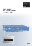
tel
TELCO User Manual SG 10 Series
Technical Data
Sensing range
2.5 - 10 m
Supply voltage
11 - 36 V dc
Voltage ripple
15% (within supply range)
Reverse polarity protected
Yes
Short circuit protection
Yes
Inductive load protection
Yes
Receiver (one): 50 mA
Transmitter (one): max. 100 mA.
Power consumption
Maximum output load
200 mA, 36 V dc
> 100.000 lux @ 5º
Light immunity
-20 to + 65 º C.
Temperature, operation
Output
Model
Output type
SGR 10-XXX-0XX-A1-X-M-07-X
SGR 10-XXX-0XX-A1-X-S-07-X
OPTO RELAY
OPTO RELAY
Output mode
Object
Output switch
Yellow LED
Light operated (NC)
Absent
Closed
On
Light operated (NC)
Present
Open
Off
Light operated (NC)
Absent
Closed
On
Light operated (NC)
Present
Open
Off
Wiring diagram
MASTER TX
SGT 10-XXX-0XX-A1-X-M-X
BROWN
Extension
cable
Extension
cable
COMMON 0V
BROWN
WHITE
WHITE
BLUE
BLUE
BLACK
BLACK
+ SUPPLY
+ SUPPLY
OPTOISOLATED
RELAY OUTPUT
MASTER RX
SGR 10-XXX-0XX-A1-X-M-07-X
BROWN
BROWN
BLACK
BLACK
BLACK
BLACK
BLUE
BLUE
WHITE
WHITE
N.C.
SLAVE RX
SGR 10-XXX-0XX-A1-X-S-07-X
SLAVE TX
SGT 10-XXX-0XX-A1-X-S-X
+ SUPPLY
BROWN
BROWN
WHITE
WHITE
BLUE
BLUE
BLACK
BLACK
Fig. 1
*
Extension
cable
BROWN
BROWN
BLACK
BLACK
BLACK
BLACK
BLUE
BLUE
WHITE
WHITE
+ SUPPLY
OPTOISOLATED
RELAY OUTPUT
N.C.
COMMON SYNCRONIZATION
*
Extension
cable
* Relay type: Normally Open
0666220608
Page 1 of 2
tel
TELCO User Manual SG 10 Series
Installation
MASTER RX
MASTER TX
WALL
WALL
SLAVE TX
SLAVE RX
Fig. 2
- Mount the detectors in correct position and correctly aligned according to Fig. 2 (Note *)
TX
RX
- It is recommended that the detectors are placed at least 5mm from edges for mechanical protection.
- Wire the detectors according to the wiring diagram. Make sure the load does not exceed 200 mA.
Alarm indicator
Output indicator
Power on indicator
- Check for correct wiring before turning power on (Fig. 1).
- When the Power on indicators (green LEDs) are on, the system is operating.
- Make sure that the Output indicator (yellow LED) changes when beams are blocked.
- If the Alarm indicator (red LED) is constant on the RX is not connected to master TX.
Fig. 3
* The master TX and master RX can run seperatly if required.
Troubleshooting
Symptom
Probable Reason
Corrective Action
1. Alarm indicator on RX is constant on.
- Master TX is disabled
Check supply and cable to the master TX
- No syncronization signal
Connect RX to master TX
2. Output indicator is flashing.
- Severe electrical interference
Remove RX and TX supply cable from high voltage cables
3. Yellow LED on RX is constant off.
0666220608
- Severe ambient light
Change position of TX and RX
- RX cannot see TX
Remove obstruction
Page 2 of 2