1
A
RE
F
S
E
-FRIEND
Y
R
E
IG
RA N
T
G
AIR COOLED WATER CHILLERS
AND HEAT PUMPS WITH AXIAL FANS
O
L
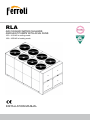
RLA
C
162 ÷ 413 kW in cooling mode
168 ÷ 435 kW in heating mode
INSTALLATION MANUAL
1
Dear Customer,
Thank you for having purchased a FERROLI Idustrial coolers. It is the result of many years experience, particular research and has
been made with top quality materials and higlly advanced technologies.The CE mark guaranteed thats the appliances meets European Machine Directive requirements regarding safety.
The qualitative level is kept under constant surveillance. FERROLI products therefore offer SAFETY, QUALITY and RELIABILITY.
'XHWRWKHFRQWLQXRXVLPSURYHPHQWVLQWHFKQRORJLHVDQGPDWHULDOVWKHSURGXFWVSHFL¿FDWLRQDVZHOODVSHUIRUPDQFHVDUHVXEMHFWWR
variations without prior notice.
Thank you once again for your preference.
FERROLI S.p.A
The manufacturer declines all responsibility for any inaccuracies in this manual due to printing or typing errors.
The manufacturer reserves the right to modify the products contents in this catalogue without previous notice.
2
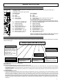
TABLE OF CONTENTS
THIS MANUAL IS DIVIDED INTO SECTIONS. THEIR NAMES APPEAR IN THE HEADING OF EACH PAGE.
GENERAL SPECIFICATIONS. . . . . . . . . . . . . . . . . . . . . . . . . . . . . . . 4
Presentation of the unit . . . . . . . . . . . . . . . . . . . . . . . . . . . . . . . . . 4
General specifications . . . . . . . . . . . . . . . . . . . . . . . . . . . . . . . . . . 4
European Directives. . . . . . . . . . . . . . . . . . . . . . . . . . . . . . . . . . . . 4
Identification plate of the Unit. . . . . . . . . . . . . . . . . . . . . . . . . . . . . 5
Identification code of the unit . . . . . . . . . . . . . . . . . . . . . . . . . . . . . 5
Description of the components. . . . . . . . . . . . . . . . . . . . . . . . . . . . 6
Version with Desuperheater VD
(available for both IR units and IP units) . . . . . . . . . . . . . . . . . . . . 8
ACCESSORIES AND OPTIONAL EQUIPMENT. . . . . . . . . . . . . . . . . 9
Mechanical accessories . . . . . . . . . . . . . . . . . . . . . . . . . . . . . . . . . 9
Electrical accessories. . . . . . . . . . . . . . . . . . . . . . . . . . . . . . . . . . . 11
Mechanical options . . . . . . . . . . . . . . . . . . . . . . . . . . . . . . . . . . . . 11
Electrical options . . . . . . . . . . . . . . . . . . . . . . . . . . . . . . . . . . . . . . 11
GENERAL TECHNICAL SPECIFICATION . . . . . . . . . . . . . . . . . . . . . 12
General technical specifications. . . . . . . . . . . . . . . . . . . . . . . . . . . 12
NOMINAL PERFORMANCES . . . . . . . . . . . . . . . . . . . . . . . . . . . . . . . 13
Standard unit AB - medium temperature plant . . . . . . . . . . . . . . . . 13
Standard unit AB - low temperature plant . . . . . . . . . . . . . . . . . . . 13
Low noise unit AS - medium temperature plant . . . . . . . . . . . . . . 14
Low noise unit AS - low temperature plant. . . . . . . . . . . . . . . . . . . 14
Extra low noise unit AX - medium temperature plant . . . . . . . . . . 15
Extra low noise unit AX - low temperature plant. . . . . . . . . . . . . . . 15
STANDARD PERFORMANCES - IR COOLING UNIT ONLY. . . . . . . 16
Performance - Standard unit AB . . . . . . . . . . . . . . . . . . . . . . . . . . 16
Performance - Low noise unit AS. . . . . . . . . . . . . . . . . . . . . . . . . . 17
Performance - Extra low noise unit AX. . . . . . . . . . . . . . . . . . . . . . 18
STANDARD PERFORMANCES - IP HEAT PUMP UNITS . . . . . . . . . 19
Performances in cooling mode - Standard Unit AB . . . . . . . . . . . . 19
Performances in heating mode - Standard Unit AB . . . . . . . . . . . . 20
Performances in cooling mode - Low noise Unit AS . . . . . . . . . . . 21
Performances in heating mode - Low noise Unit AS . . . . . . . . . . . 22
Performances in cooling mode - Extra low noise Unit AX . . . . . . . 23
Performances in heating mode - Extra low noise Unit AX . . . . . . . 24
CORRECTION FACTOR FOR THE USE OF GLYCOL . . . . . . . . . . . 25
Correction factor for the use of glycol IN HEATING MODE . . . . . . 25
Correction factor for the use of glycol IN COOLING MODE . . . . . 25
GENERAL SPECIFICATIONS - BRINE UNIT BR - BP. . . . . . . . . . . . 26
Brine Unit BR - BP . . . . . . . . . . . . . . . . . . . . . . . . . . . . . . . . . . . . . 26
GENERAL SPECIFICATIONS - VERSION WITH DESUPERHEATER (VD) 27
IR COOLING UNIT ONLY . . . . . . . . . . . . . . . . . . . . . . . . . . . . . . . . . . 27
Acoustic Version: AB (Standard Unit) . . . . . . . . . . . . . . . . . . . . . . 27
Acoustic Version: AS (Low noise Unit) . . . . . . . . . . . . . . . . . . . . . 27
Acoustic Version: AX (Extra low noise Unit) . . . . . . . . . . . . . . . . . 27
Performans Version with Desuperheater (VD) . . . . . . . . . . . . . . . 28
GENERAL SPECIFICATIONS - VERSION WITH DESUPERHEATER (VD) 29
IP HEAT PUMP UNIT. . . . . . . . . . . . . . . . . . . . . . . . . . . . . . . . . . . . . . 29
Acoustic Version: AB (Standard Unit) . . . . . . . . . . . . . . . . . . . . . . 29
Acoustic Version: AS (Low noise Unit) . . . . . . . . . . . . . . . . . . . . . 29
Acoustic Version: AX (Extra low noise Unit) . . . . . . . . . . . . . . . . . 29
Performans Version with Desuperheater (VD) . . . . . . . . . . . . . . . 30
GENERAL SPECIFICATIONS FULL HEAT RECOVERY UNIT (VR) - IP HEAT PUMP UNIT . . . . . . 31
Acoustic Version: AB (Basic Unit) . . . . . . . . . . . . . . . . . . . . . . . . . 31
Acoustic Version: AS (Low noise Unit) . . . . . . . . . . . . . . . . . . . . . 31
Acoustic Version: AX (Extra Low noise Unit) . . . . . . . . . . . . . . . . . 31
Full Heat recovery unit performans (VR) . . . . . . . . . . . . . . . . . . . . 32
NOISE LEVELS . . . . . . . . . . . . . . . . . . . . . . . . . . . . . . . . . . . . . . . . . . 33
Standard Unit AB . . . . . . . . . . . . . . . . . . . . . . . . . . . . . . . . . . . . . . 33
Low noise unit AS. . . . . . . . . . . . . . . . . . . . . . . . . . . . . . . . . . . . . . 33
Extra low moise unit AX . . . . . . . . . . . . . . . . . . . . . . . . . . . . . . . . . 33
OPERATING RANGE . . . . . . . . . . . . . . . . . . . . . . . . . . . . . . . . . . . . . 34
Operating range . . . . . . . . . . . . . . . . . . . . . . . . . . . . . . . . . . . . . . . 34
WATER PRESSURE DROP EVAPORATOR . . . . . . . . . . . . . . . . . . . 35
Operating range . . . . . . . . . . . . . . . . . . . . . . . . . . . . . . . . . . . . . . . 35
WATER PRESSURE DROP DESUPERHEATER . . . . . . . . . . . . . . . . 36
Operating range . . . . . . . . . . . . . . . . . . . . . . . . . . . . . . . . . . . . . . . 36
WORKING HEAD OF THE PUMPING MODULE
MP AM STD AND MP SS STD . . . . . . . . . . . . . . . . . . . . . . . . . . . . . . 37
Operating range . . . . . . . . . . . . . . . . . . . . . . . . . . . . . . . . . . . . . . . 37
HIGH WORKING HEAD OF THE PUMPING MODULE
MP AM HP1 AND MP SS HP1. . . . . . . . . . . . . . . . . . . . . . . . . . . . . . . 38
Operating range . . . . . . . . . . . . . . . . . . . . . . . . . . . . . . . . . . . . . . . 38
RECEPTION AND POSITIONING . . . . . . . . . . . . . . . . . . . . . . . . . . . . 39
Inspections on arrival . . . . . . . . . . . . . . . . . . . . . . . . . . . . . . . . . . . 39
Safety prescriptions . . . . . . . . . . . . . . . . . . . . . . . . . . . . . . . . . . . . 39
Handling . . . . . . . . . . . . . . . . . . . . . . . . . . . . . . . . . . . . . . . . . . . . . 39
Stoccaggio . . . . . . . . . . . . . . . . . . . . . . . . . . . . . . . . . . . . . . . . . . . 39
DIMENSIONAL DATA . . . . . . . . . . . . . . . . . . . . . . . . . . . . . . . . . . . . . 40
Overall dimensions. . . . . . . . . . . . . . . . . . . . . . . . . . . . . . . . . . . . . 40
Description of the components. . . . . . . . . . . . . . . . . . . . . . . . . . . . 40
Minimum space required for operation. . . . . . . . . . . . . . . . . . . . . . 40
Position of condensate drain . . . . . . . . . . . . . . . . . . . . . . . . . . . . . 41
Vibration-damper installation . . . . . . . . . . . . . . . . . . . . . . . . . . . . . 41
Area of support. . . . . . . . . . . . . . . . . . . . . . . . . . . . . . . . . . . . . . . . 41
Weight during transport . . . . . . . . . . . . . . . . . . . . . . . . . . . . . . . . . 42
Weight during operation . . . . . . . . . . . . . . . . . . . . . . . . . . . . . . . . . 43
HYDRAULIC CONNECTIONS. . . . . . . . . . . . . . . . . . . . . . . . . . . . . . . 45
General rules . . . . . . . . . . . . . . . . . . . . . . . . . . . . . . . . . . . . . . . . . 45
Hydraulic layout of the system . . . . . . . . . . . . . . . . . . . . . . . . . . . . 45
Precautions for the Winter . . . . . . . . . . . . . . . . . . . . . . . . . . . . . . . 45
Basic diagram Standard Unit VB [COLD WATER CIRCUIT] . . . . . 46
Basic diagram for units with Desuperheater [HOT WATER CIRCUIT]46
Air vent and water drain . . . . . . . . . . . . . . . . . . . . . . . . . . . . . . . . . 47
Plumbing connection with Victaulic couplings and Water flow switch 47
Valve regulating diagram valve . . . . . . . . . . . . . . . . . . . . . . . . . . . 47
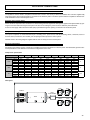
ELECTRICAL CONNECTIONS . . . . . . . . . . . . . . . . . . . . . . . . . . . . . . 49
General rules . . . . . . . . . . . . . . . . . . . . . . . . . . . . . . . . . . . . . . . . . 49
Structure of the electric panel . . . . . . . . . . . . . . . . . . . . . . . . . . . . 49
Composition of the system. . . . . . . . . . . . . . . . . . . . . . . . . . . . . . . 49
Electrical connections . . . . . . . . . . . . . . . . . . . . . . . . . . . . . . . . . . 49
R410A PROTECTION DEVICES . . . . . . . . . . . . . . . . . . . . . . . . . . . . . 52
SERIAL INTERFACE: RS485 MODBUS® RTU . . . . . . . . . . . . . . . . . 53
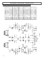
REFRIGERANT FLOW DIAGRAM - STANDARD UNIT VB . . . . . . . . 56
Refrigerant flow diagram in cooling mode IR . . . . . . . . . . . . . . . . . 56
Refrigerant flow diagram in heating mode IP . . . . . . . . . . . . . . . . . 57
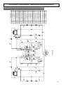
REFRIGERANT FLOW DIAGRAM VERSION WITH DESUPERHEATERS VD . . . . . . . . . . . . . . . . . . . . . 58
Refrigerant flow diagram in cooling mode IR . . . . . . . . . . . . . . . . . 58
Refrigerant flow diagram in heating mode IP . . . . . . . . . . . . . . . . . 59
START-UP . . . . . . . . . . . . . . . . . . . . . . . . . . . . . . . . . . . . . . . . . . . . . . 60
General Rules . . . . . . . . . . . . . . . . . . . . . . . . . . . . . . . . . . . . . . . . 60
MAINTENANCE . . . . . . . . . . . . . . . . . . . . . . . . . . . . . . . . . . . . . . . . . . 60
General Rules . . . . . . . . . . . . . . . . . . . . . . . . . . . . . . . . . . . . . . . . 60
Routine maintenance . . . . . . . . . . . . . . . . . . . . . . . . . . . . . . . . . . . 60
General considerations . . . . . . . . . . . . . . . . . . . . . . . . . . . . . . . . . 61
SAFETY AND POLLUTION. . . . . . . . . . . . . . . . . . . . . . . . . . . . . . . . . 62
General recommendations about the R410A refrigerant used. . . . 62
First aid . . . . . . . . . . . . . . . . . . . . . . . . . . . . . . . . . . . . . . . . . . . . . 64
3
GENERAL SPECIFICATIONS
Presentation of the unit
This new series of industrial chillers and heat pumps has been designed to meet the demands of global markets in the small-medium
power industrial and commercial plants. Units are compact and highly configurable, built to fit different types of plants so to meet the
needs of highly qualified engineers.
Units are water chillers and heat pumps condensed in air with axial fans suitable for outdoor installation: the structure and panels are
UREXVWPDGHRIJDOYDQL]HGDQGSDLQWHGVWHHODOOIDVWHQHUVDUHPDGHRIVWDLQOHVVVWHHORUJDOYDQL]HGVWHHOWKHIUDPHFRQWDLQLQJWKH
electrical equipment and all the components exposed to weather have a minimum IP54 degree of protection.
7KLVVHULHVLVFRPSRVHGRIVHYHQPRGHOVGLYLGHGLQVL]HVZLWKQRPLQDOFRROLQJFDSDFLW\IURPWRN: and thermal capacity
IURPWRN:
The units product cold water from 5 to 25°C (in summer) and hot water from 30 to 55°C (in winter) and as optional they are equipped
ZLWKFRQWLQXRXVDGMXVWPHQWRID[LDOIDQVURWDWLQJVSHHGLQRUGHUWRDOORZWKHXQLWVWRRSHUDWHERWKZLWKORZRXWGRRUWHPSHUDWXUHLQ
cooling mode and with high outdoor temperature in heating mode as well as to reduce noise emissions.
All the units are equipped with 4 scroll compressors arranged in pairs (tandem) on 2 circuits operating with environmental friendly
R410AJDVEUD]HGSODWHKHDWH[FKDQJHUFRPSOHWHO\LQVXODWHGDQGSURWHFWHGE\ZDWHUVLGHZLWKDGLIIHUHQWLDOSUHVVXUHFRQWURODQG
ZLWKDQDQWLIUHH]HHOHFWULFDOKHDWHUHOHFWURQLFH[SDQVLRQYDOYHFRLOKHDWH[FKDQJHUPDGHRIORXYHUDOXPLQXPILQVDQGFRSSHUWXEHV
axial fans with profiled blades to contain noise and with thermal protection built-in, on-board electrical control panel equipped with
control system to manage the main functions.
Hydronic group (MP) composed of fittings and connections is available as an accessory with 1 or 2 pumps and also with high
DYDLODEOHKHDGSXPSVWKHDFFHVVRU\:DWHU6WRUDJH7DQN6$$LVFRPSOHWHO\LQVXODWHGDQGDYDLODEOHRQGHOLYHU\VLGHRUIRUSULPDU\
secondary hydraulic circuit (Victaulic connections already in place) depending on the kind of plants to serve.
A variety of other accessories are available to extend the capabilities of the units.
During the design of the units particular attention has been given to achieve high system efficiency, to reduce overall energy
consumptions and sound levels in order to meet the increasingly restrictive laws in terms of noise. Upon request, you can choose for
a Standard Unit (AB) a Low Noise Unit (AS) which provides sound attenuation thanks to sound absorbing insulation in compressors
DUHDVRXQGMDFNHWVRQFRPSUHVVRUVDKHDGSUHVVXUHFRQWUROWRUHGXFHD[LDOIDQVVSHHGRUDQ([WUD/RZ1RLVH8QLW$;ZKLFK
provides in addition slower axial fans, more powerful finned coils and activation logic of the compressors in saturation.
All units are accurately build in compliance with the existing standards and are individually tested in factory. Only electrical and
hydraulic connections are required for installation.
General specifications
7KLVPDQXDODQGWKHZLULQJGLDJUDPVXSSOLHGZLWKWKHXQLWPXVWEHNHSWLQDGU\SODFHDQGUHDG\WRKDQGIRUIXWXUHFRQVXOWDWLRQ
when required.
7KLVPDQXDOKDVEHHQFRPSLOHGWRHQVXUHWKDWWKHXQLWLVLQVWDOOHGLQWKHFRUUHFWZD\DQGWRVXSSO\FRPSUHKHQVLYHLQIRUPDWLRQ
about how to correctly use and service the appliance. Before proceeding with the installation phase, please carefully read
all the information in this manual, which describes the procedures required to correctly install and use the unit.
6WULFWO\FRPSO\ZLWKWKHLQVWUXFWLRQVLQWKLVPDQXDODQGFRQIRUPWRWKHFXUUHQWVDIHW\VWDQGDUGV
7KHDSSOLDQFHPXVWEHLQVWDOOHGLQDFFRUGDQFHZLWKWKHODZVLQIRUFHLQWKHFRXQWU\LQZKLFKWKHXQLWLVLQVWDOOHG
8QDXWKRUL]HGWDPSHULQJZLWKWKHHOHFWULFDODQGPHFKDQLFDOHTXLSPHQWZLOOVOID THE WARRANTY.
&KHFNWKHHOHFWULFDOVSHFL¿FDWLRQVRQWKHLGHQWL¿FDWLRQSODWHEHIRUHPDNLQJWKHHOHFWULFDOFRQQHFWLRQV5HDGWKHLQVWUXFWLRQVLQ
WKHVSHFL¿FVHFWLRQZKHUHWKHHOHFWULFDOFRQQHFWLRQVDUHGHVFULEHG
,IWKHXQLWPXVWEHUHSDLUHGIRUDQ\UHDVRQWKLVPXVWRQO\EHGRQHE\DVSHFLDOL]HGDVVLVWDQFHFHQWHUUHFRJQL]HGE\WKH
manufacturer and using geuine spare parts.
7KHPDQXIDFWXUHUDOVRGHFOLQHVDOOOLDELOLW\IRUDQ\GDPDJHWRSHUVRQVRUSURSHUW\GHULYLQJIURPIDLOXUHRIWKHLQIRUPDWLRQLQWKLV
manual to correspond to the actual machine in your possession.
3URSHUXVHVWKLVVHULHVRIFKLOOHUVLVGHVLJQHGWRSURGXFHFROGRUKRWZDWHUIRUXVHLQK\GURQLFV\VWHPVIRU
conditioning/heating purposes. The units are not suitable for the production of domestic hot water.
Any use differing from this proper use or beyond the operating limits indicated in this manual is forbidden unless
previously agreed with the manufacturer.
7KHSUHYHQWLRQRIWKHULVNRI¿UHDWWKHLQVWDOODWLRQVLWHLVWKHUHVSRQVLEOLW\RIWKHHQGXVHU
European Directives
The company hereby declares that the machine in question complies with the matters prescribed by the following Directives:
0DFKLQH'LUHFWLYH
/RZYROWDJH'LUHFWLYH
(OHFWURPDJQHWLFFRPSDWLELOLW\'LUHFWLYH
'LUHFWLYHJRYHUQLQJSUHVVXUL]HGYHVVHOV
Any other Directives have to be considered not applicable.
4
98/37 EEC
73/23 EEC
EMC 89/336 EEC;
97/23 EEC
GENERAL SPECIFICATIONS
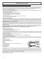
Identification plate of the Unit
The figure on the left depicts the identification plate of the unit, affixed to the outer left-hand side of
the Electric Panel.
A description of the data is given below:
Codice
Code
B1
Rev
Standard versions
A - Trademark
B - Model
B1- Code
C - Serial number
D - Cooling Capacity
E - Heating Capacity
F GHI L MNOPQRS-
Power input in COOLING mode
Power input in HEATING mode
Reference standard
Electric power supply
Maximum load current
Type of refrigerant and charge
Shipping weight of the unit
Sound pressure level at 1m
IP Level Protection
Maximum pressure - High Side
Maximum pressure - Low Side
PED certification authority
Ferroli Spa
Via Ritonda 78/A
Special versions
A - Trademark
B - Model
B1- Code
C - Serial number
D - Cooling Capacity (same as Standard Version of the unit)
E - Heating Capacity
for IR unit, VD version, Recovered Heating Capacity
for IP unit, VD version, Heating Capacity / Recovered Heating Capacity
F - Power input in COOLING mode (same as Standard version of the unit)
G - Power input in HEATING mode
H - Reference standard
I - Electric power supply
L - Maximum load current
M - Type of refrigerant and charge
N - Shipping weight of the unit
O - Sound pressure level at 1m
P - IP Level Protection
Q - Maximum pressure - High Side
R - Maximum pressure - Low Side
S - PED certification authority
NOTE: The identification plate of the Brine Unit (BR - BP) is filled out as
shown in the diagram for the Basic Version of the unit (VB).
(VR) Italy
Identification code of the unit
The codes that identify the units are listed below and include the sequences of letters that determine the meanings for the various
versions and set-ups.
RLA IP - 200.4 - VB - AB - 0 - M - 5
Unit type
IR- units suitable for hydronic plant
installation operating as chillers.
IP- units suitable for hydronic plant
installation operating as heat pumps.
BR- units suitable for hydronic plant
installation with Brine solutions
operating as chillers.
BP- units suitable for hydronic plant
installation with Brine solutions
operating as heat pumps.
Power Supply
5 - 400V-3ph~50Hz
Type of Refrigerant
0 - R410A
Operating range
Unit model
N° Compressor
Unit version
VB - Standard unit
VD- Desuperheater unit
VR- Full heat recovery unit
Acoustic Version
AB - Standard unit
AS - Low noise unit
AX - Extra low noise unit
M - Medium temperature. Units are
suitable to be installed in temperate
climate sites.
A - High temperature. Units are suitable
to be installed in tropical climate sites.
The available special versions are described below:
VB: Standard unit.
VD: Version with Desuperheater (available forboth IR units and IP units)
Produces cold water in the same way as the standard version plus hot water from 30 to 70°C at the same time. This is achieved by installing a
water-refrigerant gas heat exchanger between the compressor and coils in order to recover 20 to 25% of the heating capacity that would otherwise
be dispersed in the air.
It helps to remind that hot water production is possible only in combination with cold-hot water production in the main heat exchanger and it is
subordinated by it.
VR: Total Heat Recovery version
Produces cold water as in the standard version plus hot water at a temperature of 35 to 55°C at the same time. This is achieved thanks to a waterrefrigerant gas heat exchanger that totally recovers the heating capacity that would otherwise be dispersed in the air. The total heat recovery
function is enabled and disabled by means of a valve on the compressor delivery of each circuit: when the temperature of the water that enters
the recuperator drops, the valve switches the hot gas flow from the condensing coils to the recovery heat exchanger. On the other hand, when the
temperature of the water reaches the set-point, the valve shuts off the heat recuperator and switches the hot gas flow to the condensing coils.
It helps to remind that hot water production is possible only in combination with cold water production in the main heat exchanger and it is subordinated by it.
5
GENERAL SPECIFICATIONS
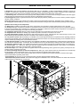
Description of the components
1. Fans. These are the helical type with scythe-shaped blades to increase the efficiency and reduce the noise level. The fans are
directly coupled to the single-phase motor by means of an external rotor. Thermal protection against operating faults is installed insiGHWKHZLQGLQJ$VVWDQGDUGWKH\DUHHTXLSSHGZLWKFRQWLQXRXVDGMXVWPHQWRID[LDOIDQVURWDWLQJVSHHGLQRUGHUWRDOORZWKHXQLWVWR
operate both with low outdoor temperature in cooling mode and with high outdoor temperature in heating mode.
2. Electric control and monitoring panel.
It is housed in a cabinet made of adequately thick painted sheet metal suitable for outdoor installation (protection degree IP 54). The
panel comprises the following main components:
- Main door-locking circuit-breaker.
- Fuse holders with protection fuses for each compressor.
)XVHKROGHUVZLWKSURWHFWLRQIXVHVIRUWKHDQWLIUHH]HKHDWHU
- Fuse holders and protection fuses for the fans (accessories).
- Fan control contactors.
- Insulating and safety transformer to power the auxiliaries, protected with fuses.
- Basic monitoring board with microprocessor
Control system main functions:
temperature control of the water produced by the unit, compressor and pump operating hour counter, timing and cycling of start-ups,
input parameters by keyboard, alarms management, smart defrosting control and operating mode change (only IP unit), dynamic setpoint (climatic control), scheduling and integrative heaters control ATC. If you installed the hydronic kit these functions are enabled:
DQWLIUHH]HZLWKSXPSVWDUWXSF\FOHDIWHUSURORQJHGLQDFWLYLW\DQWLVWLFNLQJLIWKHK\GURQLFNLWLQVWDOOHGKDVSXPSVWKHUHLVDF\FOLQJ
between each pump to ensure an equivalent lifetime.
Digital input functions: low pressure, high pressure, high temperature on compressor supply, phase presence and sequence monitoring device on power supply, differential water pressure control, compressors thermal protection, fans thermal protection, pumps
thermal protection (only if installed MP accessory), remote ON/OFF and remote operating mode change E/I (only IP unit), demand
limit, double Set-point.
Digital output functions: compressor start-up, pump start-up (only with MP accessory), plate heat exchanger electrical heater,
remote general alarm, 4-way valve (only IP unit), additional heating management, available digital contact on compressors running.
Analogic input functions: in and out water temperature, coil temperature probe, external air temperature probe.
Analogic output functions: FRQWLQXRXVDGMXVWPHQWRID[LDOIDQVURWDWLQJVSHHGLILQVWDOOHG
Moreover the controller allows:
- Alarm history (max 50m alarms managed with FIFO logic)
- Time scheduling (daily and weekly)
- Precise control of the water leaving temperature
- ATC (Advanced Temperature Control) prevention of the block of the unit: In case of critical conditions the machine does not stop
but is able to regulate itself and provide the maximum power that can be generated in those conditions with the compressors working
inside the admissible limits.
-Demand Limit by Digital Input and/or by Analog Input (4-20mA)
-Double Set Point by Digital Input
-Connection to BMS (supervision systems) through serial port RS 485 and MODBUS protocol
3. User interfacing terminal with display.
&RQWUROSDQHOFRPSRVHGRIWKHLQVWUXPHQW¶VIURQWSDQHOHTXLSSHGZLWKDQ/&'GLVSOD\WKUHHLQGLFDWRU/('VDQGRQHMR\VWLFNEXWWRQV
and three function button, it enables viewing and/or checking the operating mode and parameters, resources and complete alarm
diagnostics.
In particular, it enables:
1
2
3
4
· Managing alarm situations
· Checking the status of resources.
KEY
1.Display
2. Alarms LED
3. LED for communication between the motherboard governing
6
5
the unit and the keypad
4. Power supply LED
5. Joystick Menu Button
6. Function Button
4. Compressors. They are the SCROLL type with orbiting coil equipped with built-in thermal protection and oil heater. The version
XQLW$6DQG$;LQFOXGHVDVRXQGSURRILQJMDFNHWIRUWKHFRPSUHVVRUVDFRXVWLFFODGGLQJIRUWKHHQWLUHFRPSUHVVRUFRPSDUWPHQWWR
UHGXFHWKHQRLVHOHYHODQGFRQWLQXRXVDGMXVWPHQWRID[LDOIDQVURWDWLQJVSHHG$OOXQLWVDUHHTXLSSHGZLWKIRXUFRPSUHVVRUVFRQQHFted in parallel (2 cooling circuits) which can operate at the same time (100% cooling power) or individually (75-50-25% of the cooling
power), thus adapting to the different thermal loads of the system supplied.
5. Frame structure PDGHRIJDOYDQL]HGVKHHWPHWDOSDQHOVFRDWHGZLWKSRO\XUHWKDQHSRZGHUSDLQWWRHQVXUHPD[LPXQSURWHFWLRQ
against adverse weather conditions.
6
GENERAL SPECIFICATIONS
6. Evaporator PDGHRIEUD]HGVWDLQOHVVVWHHOSODWHV$,6,,WLVLQVWDOOHGLQDVKHOORIKHDWLQVXODWLQJPDWHULDOWRSUHYHQWWKH
IRUPDWLRQRIFRQGHQVDWLRQDQGKHDWH[FKDQJHVWRZDUGVWKHRXWVLGH6WDQGDUGVXSSO\DOVRLQFOXGHVDQWLIUHH]HKHDWHUDGLIIHUHQWLDO
SUHVVXUHVZLWFKRQWKHZDWHUFLUFXLWWRDYRLGWKHULVNRIIUHH]LQJLIWKHZDWHUIORZLVVKXWRIIIRUVRPHUHDVRQ
7. Condensing coils, the aluminium finned pack type with shaped profile to increase the heat exchange coefficient and with copper
pipes arranged in staggered rows. A sub-cooling section is integrated into the lower part.
8. Covering panels, PDGHRIJDOYDQL]HGVKHHWPHWDOFRDWHGZLWKSRO\XUHWKDQHSRZGHUSDLQWWRHQVXUHPD[LPXQSURWHFWLRQDJDLQVW
adverse weather conditions
9.One-way valves (IP unit only), allowing the coolant to pass into the appropriate exchangers, depending on the operating cycle.
10. 4-way cycle reversal valve (IP unit only), reverses the flow direction of the gas as the summer/winter operating mode is changed.
Hydraulic and cooling circuit components
11. Safety valve. Installed on the delivery pipe of the compressors, this operates if extreme faults should occur in the plant.
12. Fluid tap. Ball type, this allows the gas flow on the fluid line to be turned on and off. Along with the tap on the compressor delivery,
LWDOORZVWKHFRPSRQHQWVRIWKHIOXLGOLQHWREHVXEMHFWHGWRH[WUDRUGLQDU\PDLQWHQDQFHZRUNDQGWKHFRPSUHVVRUVWREHUHSODFHGLI
necessary (without discharging the coolant from the unit): pump down.
13. Compressor delivery tap. Ball type, allows the gas delivered to the compressors to be turned on and off.
14. Dehydrator filter. Mechanical cartridge type. Retains impurities and traces of moisture in the circuit.
15. Fluid and humidity indicator. Signals when fluid passes through the circuit, indicating that the coolant charge is correct. The
fluid indicator light also indicates the amount of moisture in the coolant by changing colour.
16. Low pressure switch. With fixed setting. It is installed on the suction pipe and blocks the compressors if the operating pressures
drop below the tolerated values. Automatically resets as the pressure increases. If it activates frequently, the unit will block and can
only be restarted by resetting via the user interface terminal.
17. High pressure switch (n°2). With fixed setting. Are is installed on the delivery pipe and blocks the compressors if the operating pressures exceed the tolerated values. If it activates, the unit will block and can only be restarted by resetting via the user interface terminal.
18. Electronic expansion valve. This supplies the evaporator correctly, keeping the selected overheating degree at a steady level.
19. Pressure taps: 1/4 “ SAE (7/16” UNF) type with flow regulator. Allow the operating pressure of the system to be measured:
compressor delivery, lamination component inlet, compressor intake.
20. Pressure taps: 5/16 “ SAE type with flow regulator. Allow the charge/discharge of the gas from the system, precisely from compressor outlet an expansion valve inlet.
21. Electrical heating elements to heat the compressor oil. “Belt” type. These activate when the compressor turns off and keep
the temperature of the oil sufficiently high so as to prevent coolant from migrating during these pauses.
- Fluid receiver (IP unit only), this is a plenum tank that accounts for variations to the coolant charge the machine must supply
as the summer/winter operating mode varies.
- Fluid separator (IP unit only), on the compressor intake to protect against possible fluid back-flows.
- Water differential pressure switch. This is standard supply and is installed on the connections between the water inlet and outlet
of the exchanger. It stops the unit if it activates.
7
GENERAL SPECIFICATIONS
Version with Desuperheater VD (available for both IR units and IP units)
Hydraulic and chilling circuit components:
1. Desuperheater. Specially designed for the specific version. Plate type, made of stainless steel (AISI 316).
It is installed within a shell of thermal barrier insulating material to prevent heat exchanges towards the outside. Standard supply also
LQFOXGHVDQHOHFWULFDQWLIUHH]HKHDWHUWRSUHYHQWWKHSDUWVIURPIUHH]LQJGXULQJWKHZLQWHUZKHQWKHV\VWHPUHPDLQVDWDVWDQGVWLOOLI
not drained).
2. Water safety valve.On the heat recovery inlet pipe. It acts whenever faulty service leads to an operating pressure in the plumbing
system that exceeds the valve opening value (Fig.1).
3. Water drain cock for emptying the exchangers and pipes of the machine dedicated to heat recovery (Fig. 1).
4. Air vent. Accessed by removing the front panels. It consists of a manually operated valve installed in the highest part of the water
SLSHV7RXVHLQFRQMXQFWLRQZLWKWKHZDWHUGUDLQFRFNVVLWXDWHGLQWKHUHDUSDUWRIWKHXQLWIRUHPSW\LQJWKHH[FKDQJHUVDQGSLSHV
dedicated to heat recovery.
4
3
2
3
1
8
ACCESSORIES AND OPTIONAL EQUIPMENT
Mechanical accessories
NOTE: The accessories can be of the following type:
(M): only installed in the factory.
(F): supplied for installation by the customer.
MP. Hydronic Kit (M). Consists of:
1 On-off ball valves. Turn components such as the water filter, surge chamber and pump on and off when they require routine or extraordinary
maintenance.
2 Metal gauze water filter. Can be turned on and off and inspected. It is installed on the pump delivery side. Prevents machining residues (dust,
swarf, etc.) in the water pipes from entering the plate-type heat exchanger.
3 Hydraulic pump&LUFXODWHVZDWHUDURXQGWKHV\VWHP7KHSXPSVKDYHDORZKLJKKHDGDQGVXLWWKHPDMRULW\RILQVWDOODWLRQUHTXLUHPHQWV7KH
pumps are safeguarded by a magnetothermics installed in the chiller’s electric panel.
4 Surge chamber. This is a closed, diaphragm type chamber. It absorbs the variations in the volumes of water in the system caused by temperature
variations.
5 Water filling. Manual function with control positioned on the side of the unit opposite the electric panel and turned on and off by a cock that can
be accessed by removing the rear panel.
6 Water pressure gauge. Connected to the water fill pipe. Displays the pressure of the water in the system.
7 Water safety valve.
8 Water outlet.
9 Air vent.
10 Antifreeze heater connection (RAG accessory).
7R HQVXUH D FRQWLQXRXV RSHUDWLRQ DQ DQWLIUHH]H ZLWK SXPS IXQFWLRQ EDVHG RQ D UHDGLQJ IURP WKH RXWSXW ZDWHU SUREH DQG VWDUWLQJ F\FOLF DQWL
VWLFNLQJDIWHUSURORQJHGLQDFWLYLW\DUHHQDEOHGLIWKHK\GURQLFNLWKDVSXPSVWKHVHFRQGPRXQWHGLQSDUDOOHOWRWKHILUVWFDQEHDFWLYDWHGLQFDVH
of failure of the first and will also include a cycling period to guarantee to each pump an equivalent operating time.
MP. Hydronic Kit.
MP : Hydronic Kit with 1 (M1P) o 2 (M2P) Pumps: (The second pump, mounted in parallel to the first, allows to have a spare pump to be activated
in case of failure of the first). Besides the pumps, this accessory is equipped with all the hydraulic components (water filter, expansion tank, on-off
valves, water pressure gauge, air vent, water outlet) required for complete installation and easy maintenance.
Different water accumulation tank configurations are therefore available in combination with the Hydronic Kit accessory:
MP AM 2P STD: Accumulation on the Plant Delivery side (Standard)(A): The pump draws water from the system, sends it to the plate exchanger
and from thence to the inertial accumulation tank. During normal operating conditions, the pump in this configuration is able to provide a residue
head from 86 to 150 kPa (from 9 to 15 m.w.c.) for the circulating water.
MP AM 2P HP1: Accumulation on the Plant Delivery side (High)(B).: The pump draws water from the system, sends it to the plate exchanger and
from thence to the inertial accumulation tank. During normal operating conditions, the pump in this configuration is able to provide a residue head
from 198 to 255 kPa (from 20 to 25 m.w.c.) for the circulating water.
MP PS 2P STD: Accumulation pre-engineered for the primary and secondary circuit : The sole function of the pump is to circulate the water
around the primary circuit: this circuit includes the accumulation tank and plate exchanger (chiller water circuit). The installer must mount the pumping section relative to the secondary circuit formed by the accumulation tank (with the pre-engineered wet connections) and the system served.
No high working head version available.
MP SS 2P STD+\GURQLF.LWZLWKRXW:DWHU6WRUDJH7DQN6WDQGDUG (A). The pump draws water from the system, sends it to the plate heat exchanger and returns it to the system. During normal operating conditions, the pump in this configurations can provide a residue head from 86 to
150 kPa (from 9 to 15 m w.c.).
MP SS 2P HP1+\GURQLF.LWZLWKRXW:DWHU6WRUDJH7DQN+LJK:RUNLQJ+HDG(B). The pump draws water from the system, sends it to the plate
heat exchanger and returns it to the system. During normal operating conditions, the pump in this configurations can provide a residue head from
198 to 255 kPa (from 20 to 25 m w.c.).
Notes:
(A): For the working head values depending on the water flow rate, consult the Standard Working Head MP AM STD graph.
(B): For the working head values depending on the water flow rate, consult the High Working Head MP AM HP1 graph.
6$$:DWHU6WRUDJHWDQN0Painted steel water storage tank reduces compressor startup frequency and temperature fluctuation on water side. It
is coated with thermo insulated material to avoid air condensing and losses due to heat transfer. It is available on delivery side and also for primarysecondary hydraulic circuit interface.
:DWHUVWRUDJHWDQN,WFRQVLVWVRI
Water draining. On-off action by means of a cock that can be accessed by removing the rear panel, positioned on the side of the unit opposite
to the electric panel.
Air vent. Accessed by removing the rear panel positioned on the side of the unit opposite to the electric panel. It consists of a manually operated
valve installed on the highest part of the wet pipes.
Antifreeze heater connection.´IHPDOHWKUHDGHGFRQQHFWLRQSUHHQJLQHHUHGIRULQVWDOODWLRQRIWKHDQWLIUHH]HKHDWHU5$*DFFHVVRU\
Water safety valve, on the rear part of the tank. It acts whenever faulty service leads to an operating pressure in the hydraulic circuit that exceeds
the valve opening value.
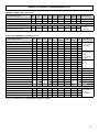
KT - the following kits are available (this accessory is mandatory if the Hydronic Kit is not installed).
9LFWDXOLFFRQQHFWLRQNLWThis accessory consists of steel pipes insulated with thermal barrier material and allows the water inlet/outlet to be
connected straight inside the unit.
&RPSOHWHSLSHNLW This accessory consists of steel pipes insulated with thermal barrier material and allows the water inlet/outlet connection to
be routed to the machine.
:DWHUVWRUDJHWDQNSLSHNLW This accessory consists of steel pipes insulated with thermal barrier material and allows the water inlet/outlet connection to be routed to the machine.
NB: YOU CAN CHOOSE ONLY ONE KIT.
BCN- Drain Pan Kit (M). Provides a pan under the coil to drain the condensing water, fitted with 1/2” outlet connection positioned opposite to the
electric control panel.
GP- Coil protection grid (M). Protects external surface of the finned coils.
*03UHVVXUHJDXJHVNLW0SUHVVXUHJDXJHVDOORZYLVXDOL]DWLRQRIKLJKDQGORZUHIULJHUDQWJDVSUHVVXUH
AVG- Rubber vibration dampers (F). Reduce vibrations transmitted to the floor by compressors and fans during normal operating conditions (until 85%).
AVM- Spring vibration dampers (F).Reduce vibrations transmitted to the floor by compressors and fans during normal operating conditions (until 90%).
9
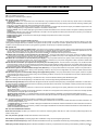
ACCESSORIES AND OPTIONAL EQUIPMENT
10
VICTAULIC CONNECTION KIT
COMPLETE PIPE KIT
WATER STORAGE TANK PIPE KIT
M1P AM 2P STD
M1P AM 2P HP1
M1P PS 2P STD
M2P AM 2P STD
M2P AM 2P HP1
M2P PS 2P STD
M1P SS 2P STD
M1P SS 2P HP1
M2P SS 2P STD
M2P SS 2P HP1
ACCESSORIES AND OPTIONAL EQUIPMENT
Electrical accessories
TP - Low and High pressure transducers (M). Allow the display of the suction and discharge pressures of compressors. Their presence
activates an advanced defrost and condensation control logic and the ATC (Advanced Temperature Control) to prevent high pressure alarm
due to high external air temperature.
5$*6WRUDJHWDQNHOHFWULFDOKHDWHU).HHSVZDWHULQVWRUDJHWDQNDERYHIUHH]LQJSRLQWWRDYRLGULVNRILFLQJGXULQJZLQWHUVWRSVLWLV
activated together with plate heat exchanger electrical heater.
TAT- High Temperature Thermostat (M). Two thermostats in series on compressors outlet pipes preserve operation not allowing temperaWXUHWRULVHXSWKDQDVSHFLILHGQRQDGMXVWDEOHYDOXH
CR- Remote control panel (F)5HSOLHVHYHU\FRQWURODQGYLVXDOL]DWLRQRIWKHRQERDUGFRQWUROSDQHO
INT- Serial interface (M). Allows serial communication on RS485 by MODBUS protocol.
MTC - Magnetothermic switch (M). Magnetothermic switch on all loads place of fuses.
SS - Soft Starter (M). Soft starter on compressors allow to reduce to about a 60% nominal inrush current.
FLS - Flow switch (F).3DGGOHIORZVZLWFKRQWKHZDWHUFLUFXLWWRDYRLGWKHULVNRIIUHH]LQJLIWKHZDWHUIORZLVVKXWRIIIRUVRPHUHDVRQ
RIF - Capacitors for power factor corrections (M). &DSDFLWRUVIRUSRZHUIDFWRUFRUUHFWLRQVLQFUHDVHSRZHUIDFWRUFRVij (> 0.91) and reduce power input.
CSF - Voltage monitor and sequence meter (M). The device enables control of the correct sequence of power phases and the lack of any
phases.
.233URJUDPPHUFORFN0Allows the unit to be turned on and off depending on the programmed time setting (up to 14 switching actions
can be programmed as required throughout the 7 days of the week).
DCC - Head pressure control (M). (as standard for Low Noise unit AS and for eXtra Low Noise unit AX).
The device is made by 2 electrical drivers that, by means of phase cutting, control the fans speed rotation, with the scope of mantaining the
condensation pressure inside the correct operating limits.
Mechanical options
Special finned heat exchangers
&RLOVZLWKFRSSHUILQV
&RLOVZLWKWLQFRDWHGFRSSHUILQV
&RLOVZLWKDOXPLQLXPILQVZLWKDFU\OLFHSR[\RUK\GURILOLFFRDWLQJ.
Electrical options
Other power source voltage rating (contact our technical department).
11
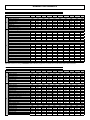
GENERAL TECHNICAL SPECIFICATION
General technical specifications
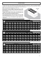
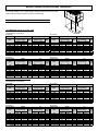
MODELS
Power supply
Refrigerant type
Refrigeration circuits
&RPSUHVVRUVSHFL¿FDWLRQV
Type
Quantity
Oil charge CP1
Oil charge CP2
Oil charge CP3
Oil charge CP4
Load steps
Heat Exchanger
Type
Quantity
Total water capacity
&RLOVVSHFL¿FDWLRQV
Type
Quantity
Total area
)DQVSHFL¿FDWLRQV
Type
Quantity
Maximum rotation speed
Total air flow rate
Power input
:DWHU6WRUDJH7DQN6$$DFFHVVRU\
Water volume
Surge chamber volume
Safety valve setting
Surge chamber default pressure
Max. operating pressure
(OHFWULFDOVSHFL¿FDWLRQV
Units without pumping module
MODELS
Total maximum load current [ FLA ]
Total maximum power input [ FLI ]
160.4
3.25
3.25
3.25
3.25
7.3
180.4
3.25
4.7
3.25
4.7
8.3
200.4
230.4
4.7
4.7
4.7
4.7
4.7
6.8
4.7
6.8
9.5
%UD]HGSODWHV
1
10.8
12.0
14.2
$OXPLQXP¿QVDQGFRSSHUWXEHV
2
5.54
5.54
5.54
5.54
5.54
4
4
4
4
82920
69100
55280
7.2
82920
69100
55280
7.2
79760
66467
53173
7.2
12
Axial
6
900
750
600
124380
103650
82920
10.8
6.8
6.3
6.8
6.3
330.4
6.3
6.3
6.3
6.3
23.0
375.4
6.3
6.3
6.3
6.3
25.7
420.4
6.3
6.3
6.3
6.3
UM
9SK+]
N°
N°
l
l
l
l
%
29.3
N°
l
N°
m2
7.41
7.41
7.41
6
6
8
8
119640
99700
79760
10.8
130599
108833
87066
10.8
165840
138200
110560
14.4
159520
132933
106347
14.4
325
160.4
180.4
200.4
141
152
163
76.8
88
98.4
Total maximum starting current [ MIC ]
284
340
352
Units with pumping module MP PS STD (1 or 2 pumps)
Total maximum load current [ FLA ]
147
158
169
Total maximum power input [ FLI ]
80
91
102
Total maximum starting current [ MIC ]
290
347
358
Units with pumping module MP AM STD and MP SS STD (1 or 2 pumps)
Total maximum load current [ FLA ]
147
158
172
Total maximum power input [ FLI ]
80
91
103
Total maximum starting current [ MIC ]
290
347
360
Units with pumping module MP AM HP1 and MP SS HP1 (1 or 2 pumps)
Total maximum load current [ FLA ]
150
161
175
Total maximum power input [ FLI ]
82
93
105
Total maximum starting current [ MIC ]
293
349
363
Data referred to standard operating condition.
(SAA): with storage tank
290.4
scroll
4
6.8
6.8
6.8
6.8
0-25-50-75-100
5.54
AB
AS
AX
AB 84350
AS 70292
AX 56233
7.2
260.4
400-3-50
R410A
2
710
N°
rpm
rpm
rpm
m3/h
m3/h
m3/h
kW
l
l
kPa
kPa
kPa
24
600
150
800
230.4
179
108
407
260.4
204
122
432
290.4
234
139
484
330.4
263
156
514
375.4
301
182
621
420.4
330
203
650
UM
186
112
413
210
126
438
245
146
496
275
163
525
312
188
633
341
210
662
A
kW
A
188
113
416
213
127
441
245
146
496
275
163
525
312
188
633
345
212
665
A
kW
A
191
115
418
216
129
443
249
148
499
278
165
529
316
188
636
352
216
672
A
kW
A
A
kW
A
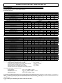
NOMINAL PERFORMANCES
230.4
260.4
290.4
330.4
375.4
420.4
UM
IR
Cooling mode A35W7 (source: air 35°C d.b. / system: water in 12°C out 7°C)
Cooling capacity (E)
162
179
201
230
Compressor power input
47.7
54.0
61.9
71.1
54.9
61.2
69.1
78.3
Total power input
2.95
2.92
2.91
2.94
EER (E)
ESEER (E)
4.13
4.09
4.07
4.11
:DWHUÀRZUDWH
7.74
8.55
9.60
11.0
Water pressure drop (E)
55
54
62
65
257
77.4
88.2
2.91
4.08
12.3
67
292
89.7
100
2.92
4.09
14.0
71
326
101
112
2.91
4.08
15.6
59
371
112
127
2.92
4.09
17.7
61
413
128
142
2.91
4.07
19.7
62
kW
kW
kW
l/s
kPa
Cooling mode A35W7 (source: air 35°C d.b. / system: water in 12°C out 7°C)
Cooling capacity (E)
155
172
194
217
246
Compressor power input
47.0
53.3
60.7
69.5
76.9
54.2
60.5
67.9
76.7
87.7
Total power input
2.86
2.84
2.86
2.83
2.81
EER (E)
ESEER (E)
4.00
3.98
4.00
3.96
3.93
:DWHUÀRZUDWH
7.41
8.22
9.27
10.4
11.8
Water pressure drop (E)
50
50
58
58
62
Heating mode A7W45 (source: air 7°C d.b. 6°C w.b. / system: water in 40°C out 45°C)
Heating capacity (E)
168
189
213
238
270
Compressor power input
48.1
55.1
62.9
71.7
79.0
55.3
62.3
70.1
78.9
89.8
Total power input
COP (E)
3.04
3.03
3.04
3.02
3.01
:DWHUÀRZUDWH
8.03
9.03
10.2
11.4
12.9
Water pressure drop (E)
59
60
70
69
74
Heating mode A2W45 (source: air 2°C d.b. 1°C w.b. / system: water in 40°C out 45°C)
Heating capacity
153
172
194
217
246
Compressor power input
47.4
54.3
62.0
70.6
77.8
Total power input
54.6
61.5
69.2
77.8
88.6
COP
2.80
2.80
2.80
2.79
2.78
:DWHUÀRZUDWH
7.30
8.22
9.26
10.3
11.7
Water pressure drop
49
50
58
57
61
278
88.4
99.2
2.80
3.92
13.3
64
312
100
111
2.81
3.94
14.9
54
360
111
126
2.86
4.00
17.2
58
401
125
140
2.86
4.01
19.2
59
kW
kW
kW
l/s
kPa
IP
Standard unit AB - MEDIUM TEMPERATURE PLANT
MOD.
160.4
180.4
200.4
305
90.4
101
3.02
14.6
77
342
102
113
3.03
16.3
65
391
114
128
3.05
18.7
68
435
129
143
3.04
20.8
69
kW
kW
kW
l/s
kPa
278
89.0
99.8
2.79
13.3
64
311
100
111
2.80
14.9
54
356
112
127
2.80
17.0
57
396
127
141
2.81
18.9
57
kW
kW
kW
l/s
kPa
(E): Data declared according to EUROVENT LCP certification programme. The values are for units without options and accessories.
230.4
260.4
290.4
330.4
375.4
420.4
UM
IR
Cooling mode A35W18 (source: air 35°C d.b. / system: water in 23°C out 18°C)
Cooling capacity
207
229
257
294
Compressor power input
50.6
57.2
65.6
75.4
Total power input
57.8
64.4
72.8
82.6
EER
3.58
3.56
3.53
3.56
:DWHUÀRZUDWH
9.91
10.9
12.3
14.1
Water pressure drop
90
87
102
106
329
82.0
92.8
3.55
15.7
110
374
95.1
106
3.53
17.9
116
417
107
118
3.53
19.9
97
475
119
133
3.57
22.7
101
529
136
150
3.53
25.3
102
kW
kW
kW
l/s
kPa
Cooling mode A35W18 (source: air 35°C d.b. / system: water in 23°C out 18°C)
Cooling capacity
198
220
248
278
315
Compressor power input
49.8
56.5
64.3
73.7
81.5
57.0
63.7
71.5
80.9
92.3
Total power input
EER
3.47
3.45
3.47
3.44
3.41
:DWHUÀRZUDWH
9.48
10.5
11.9
13.3
15.0
Water pressure drop
82
81
95
95
100
Heating mode A7W35 (source: air 7°C d.b. 6°C w.b. / system: water in 30°C out 35°C)
Heating capacity
178
200
226
252
286
Compressor power input
40.9
46.8
53.5
60.9
67.2
Total power input
48.1
54.0
60.7
68.1
78.0
COP
3.70
3.70
3.72
3.70
3.67
:DWHUÀRZUDWH
8.51
9.57
10.8
12.1
13.7
Water pressure drop
66
67
79
78
84
Heating mode A2W35 (source: air 2°C d.b. 1°C w.b. / system: water in 30°C out 35°C)
Heating capacity
159
179
202
225
256
Compressor power input
38.6
44.2
50.5
57.6
63.4
Total power input
45.8
51.4
57.7
64.8
74.2
COP
3.47
3.48
3.50
3.47
3.45
:DWHUÀRZUDWH
7.60
8.55
9.63
10.8
12.2
Water pressure drop
53
54
62
62
66
356
93.7
105
3.39
17.0
105
399
106
117
3.41
19.1
89
461
118
132
3.49
22.0
95
513
133
147
3.49
24.5
96
kW
kW
kW
l/s
kPa
IP
Standard unit AB - LOW TEMPERATURE PLANT
MOD.
160.4
180.4
200.4
323
76.8
87.6
3.69
15.4
86
363
86.7
97.5
3.72
17.3
73
414
96.9
111
3.73
19.8
77
461
110
124
3.72
22.0
77
kW
kW
kW
l/s
kPa
289
72.6
83.4
3.47
13.8
69
324
81.9
92.7
3.50
15.5
59
370
91.5
106
3.49
17.7
61
412
104
118
3.49
19.7
62
kW
kW
kW
l/s
kPa
13
NOMINAL PERFORMANCES
230.4
260.4
290.4
330.4
375.4
420.4
UM
IR
Cooling mode A35W7 (source: air 35°C d.b. / system: water in 12°C out 7°C)
Cooling capacity (E)
156
172
193
221
Compressor power input
51.5
58.3
66.9
76.8
58.7
65.5
74.1
84.0
Total power input
2.66
2.63
2.60
2.63
EER (E)
ESEER (E)
3.72
3.68
3.65
3.68
:DWHUÀRZUDWH
7.45
8.22
9.22
10.6
51
50
57
60
Water pressure drop (E)
247
83.6
94.4
2.62
3.66
11.8
62
280
96.9
108
2.59
3.63
13.4
65
313
109
120
2.61
3.65
15.0
55
356
121
135
2.64
3.69
17.0
57
396
138
152
2.61
3.65
18.9
57
kW
kW
kW
l/s
kPa
Cooling mode A35W7 (source: air 35°C d.b. / system: water in 12°C out 7°C)
149
165
186
208
236
Cooling capacity (E)
Compressor power input
50.8
57.6
65.6
75.1
83.1
Total power input
58.0
64.8
72.8
82.3
93.9
2.57
2.55
2.55
2.53
2.51
EER (E)
ESEER (E)
3.60
3.56
3.58
3.54
3.52
:DWHUÀRZUDWH
7.12
7.88
8.89
9.94
11.3
Water pressure drop (E)
46
46
53
53
57
Heating mode A7W45 (source: air 7°C d.b. 6°C w.b. / system: water in 40°C out 45°C)
Heating capacity (E)
161
181
204
228
259
Compressor power input
45.7
52.3
59.8
68.1
75.1
52.9
59.5
67.0
75.3
85.9
Total power input
COP (E)
3.04
3.04
3.04
3.03
3.02
:DWHUÀRZUDWH
7.69
8.65
9.8
10.9
12.4
Water pressure drop (E)
54
55
64
63
69
Heating mode A2W45 (source: air 2°C d.b. 1°C w.b. / system: water in 40°C out 45°C)
Heating capacity
147
165
186
207
236
Compressor power input
45.0
51.5
58.9
67.1
74.0
Total power input
52.2
58.7
66.1
74.3
84.8
COP
2.82
2.81
2.81
2.79
2.78
:DWHUÀRZUDWH
7.00
7.87
8.87
9.91
11.3
Water pressure drop
45
46
53
52
57
267
95.5
106
2.52
3.53
12.8
59
300
108
119
2.52
3.53
14.3
50
346
120
134
2.58
3.61
16.5
53
385
135
149
2.58
3.62
18.4
54
kW
kW
kW
l/s
kPa
IP
Low noise unit AS - MEDIUM TEMPERATURE PLANT
MODELLO
160.4
180.4
200.4
293
85.9
96.7
3.03
14.0
71
328
97.0
108
3.04
15.7
60
375
108
122
3.07
17.9
63
418
123
137
3.05
20.0
64
kW
kW
kW
l/s
kPa
267
84.6
95.4
2.81
12.7
58
298
95.5
106
2.81
14.3
50
341
106
121
2.82
16.3
52
380
121
136
2.79
18.2
53
kW
kW
kW
l/s
kPa
(E): Data declared according to EUROVENT LCP certification programme. The values are for units without options and accessories.
230.4
260.4
290.4
330.4
375.4
420.4
UM
IR
Cooling mode A35W18 (source: air 35°C d.b. / system: water in 23°C out 18°C)
Cooling capacity
200
220
247
283
Compressor power input
54.6
61.8
70.9
81.4
Total power input
61.8
69.0
78.1
88.6
EER
3.24
3.19
3.16
3.19
:DWHUÀRZUDWH
9.54
10.5
11.8
13.5
Water pressure drop
83
81
94
97
316
88.6
99.4
3.18
15.1
102
358
103
114
3.14
17.1
106
401
116
126
3.18
19.1
89
456
128
143
3.19
21.8
93
507
146
161
3.15
24.2
94
kW
kW
kW
l/s
kPa
Cooling mode A35W18 (source: air 35°C d.b. / system: water in 23°C out 18°C)
Cooling capacity
191
211
238
266
302
Compressor power input
53.8
61.1
69.5
79.6
88.1
61.0
68.3
76.7
86.8
98.9
Total power input
EER
3.13
3.09
3.10
3.06
3.05
:DWHUÀRZUDWH
9.11
10.1
11.4
12.7
14.4
Water pressure drop
76
75
88
86
92
Heating mode A7W35 (source: air 7°C d.b. 6°C w.b. / system: water in 30°C out 35°C)
Heating capacity
171
192
216
242
275
Compressor power input
38.8
44.5
50.8
57.9
63.8
Total power input
46.0
51.7
58.0
65.1
74.6
COP
3.72
3.71
3.72
3.72
3.69
:DWHUÀRZUDWH
8.15
9.17
10.3
11.5
13.1
Water pressure drop
61
62
71
71
76
Heating mode A2W35 (source: air 2°C d.b. 1°C w.b. / system: water in 30°C out 35°C)
Heating capacity
152
171
193
216
245
Compressor power input
36.7
42.0
48.0
54.7
60.3
Total power input
43.9
49.2
55.2
61.9
71.1
COP
3.46
3.48
3.50
3.49
3.45
:DWHUÀRZUDWH
7.28
8.18
9.22
10.3
11.7
Water pressure drop
48
49
57
57
61
342
101
112
3.05
16.3
96
384
114
125
3.07
18.3
82
443
127
142
3.12
21.2
88
493
143
158
3.12
23.5
88
kW
kW
kW
l/s
kPa
IP
Low noise unit AS - LOW TEMPERATURE PLANT
MODELLO
311
73.0
83.8
3.71
14.8
79
348
82.5
93.3
3.73
16.6
67
398
91.8
106
3.75
19.0
71
443
105
119
3.72
21.2
72
kW
kW
kW
l/s
kPa
277
69.0
79.8
3.47
13.2
63
310
77.9
88.7
3.49
14.8
53
355
86.7
101
3.51
17.0
57
396
98.7
113
3.50
18.9
57
kW
kW
kW
l/s
kPa
14
160.4
180.4
200.4
NOMINAL PERFORMANCES
230.4
260.4
290.4
330.4
375.4
420.4
UM
IR
Cooling mode A35W7 (source: air 35°C d.b. / system: water in 12°C out 7°C)
Cooling capacity (E)
152
168
189
216
Compressor power input
52.9
59.9
68.7
78.9
60.1
67.1
75.9
86.1
Total power input
2.53
2.50
2.49
2.51
EER (E)
ESEER (E)
3.54
3.51
3.49
3.51
:DWHUÀRZUDWH
7.26
8.03
9.03
10.3
Water pressure drop (E)
48
47
55
57
242
85.9
96.7
2.50
3.50
11.6
60
274
99.6
110
2.49
3.49
13.1
62
306
112
123
2.49
3.48
14.6
52
349
124
138
2.53
3.54
16.7
55
388
142
156
2.49
3.48
18.5
55
kW
kW
kW
l/s
kPa
Cooling mode A35W7 (source: air 35°C d.b. / system: water in 12°C out 7°C)
Cooling capacity (E)
146
162
182
204
231
Compressor power input
52.2
59.2
67.4
77.1
85.4
59.4
66.4
74.6
84.3
96.2
Total power input
2.46
2.44
2.44
2.42
2.40
EER (E)
ESEER (E)
3.44
3.42
3.42
3.39
3.36
:DWHUÀRZUDWH
6.98
7.74
8.70
9.75
11.0
Water pressure drop (E)
44
44
51
51
54
Heating mode A7W45 (source: air 7°C d.b. 6°C w.b. / system: water in 40°C out 45°C)
Heating capacity (E)
160
180
202
226
257
Compressor power input
44.7
51.2
58.5
66.7
73.5
51.9
58.4
65.7
73.9
84.3
Total power input
COP (E)
3.08
3.08
3.07
3.06
3.05
:DWHUÀRZUDWH
7.64
8.60
9.65
10.8
12.3
Water pressure drop (E)
53
54
63
62
67
Heating mode A2W45 (source: air 2°C d.b. 1°C w.b. / system: water in 40°C out 45°C)
Heating capacity (E)
146
164
184
206
234
Compressor power input
44.0
50.4
57.6
65.7
72.4
Total power input
51.2
57.6
64.8
72.9
83.2
COP (E)
2.85
2.85
2.84
2.83
2.81
:DWHUÀRZUDWH
6.96
7.83
8.78
9.83
11.2
Water pressure drop (E)
44
45
52
52
56
261
98.1
109
2.39
3.35
12.5
57
293
111
122
2.40
3.36
14.0
48
338
123
137
2.47
3.45
16.1
51
377
139
153
2.46
3.45
18.0
52
kW
kW
kW
l/s
kPa
IP
Extra low noise unit AX - MEDIUM TEMPERATURE PLANT
MODELLO
160.4
180.4
200.4
290
84.1
94.9
3.06
13.9
70
325
94.9
106
3.07
15.5
59
371
106
120
3.09
17.7
61
413
120
134
3.08
19.7
62
kW
kW
kW
l/s
kPa
264
82.8
93.6
2.82
12.6
57
296
93.5
104
2.85
14.1
48
338
104
119
2.84
16.1
51
376
118
133
2.83
18.0
52
kW
kW
kW
l/s
kPa
(E): Data declared according to EUROVENT LCP certification programme. The values are for units without options and accessories.
Extra low noise unit AX - LOW TEMPERATURE PLANT
180.4
200.4
230.4
260.4
290.4
330.4
375.4
420.4
UM
310
91.1
102
3.04
14.8
98
351
106
116
3.03
16.8
102
392
119
130
3.02
18.7
85
447
131
146
3.06
21.3
89
497
151
165
3.01
23.7
90
kW
kW
kW
l/s
kPa
334
104
115
2.90
16.0
93
375
118
128
2.93
17.9
78
433
130
145
2.99
20.7
84
483
147
162
2.98
23.1
85
kW
kW
kW
l/s
kPa
307
71.5
82.3
3.73
14.7
78
345
80.7
91.5
3.77
16.5
66
393
90.1
105
3.74
18.8
69
438
102
116
3.78
20.9
70
kW
kW
kW
l/s
kPa
274
67.5
78.3
3.50
13.1
62
308
76.2
87.0
3.54
14.7
53
351
85.1
99.5
3.53
16.8
55
391
96.3
111
3.52
18.7
56
kW
kW
kW
l/s
kPa
IR
160.4
IP
MODELLO
Cooling mode A35W18 (source: air 35°C d.b. / system: water in 23°C out 18°C)
Cooling capacity
195
215
242
276
Compressor power input
56.1
63.5
72.8
83.6
63.3
70.7
80.0
90.8
Total power input
EER
3.08
3.04
3.03
3.04
:DWHUÀRZUDWH
9.30
10.3
11.6
13.2
Water pressure drop
79
78
91
93
Cooling mode A35W18 (source: air 35°C d.b. / system: water in 23°C out 18°C)
Cooling capacity
187
207
233
261
296
Compressor power input
55.3
62.8
71.4
81.7
90.5
62.5
70.0
78.6
88.9
101
Total power input
EER
2.99
2.96
2.96
2.94
2.93
:DWHUÀRZUDWH
8.93
9.91
11.1
12.5
14.1
Water pressure drop
73
72
83
83
89
Heating mode A7W35 (source: air 7°C d.b. 6°C w.b. / system: water in 30°C out 35°C)
Heating capacity
170
191
214
240
272
Compressor power input
38.0
43.5
49.7
56.7
62.5
Total power input
45.2
50.7
56.9
63.9
73.3
COP
3.76
3.77
3.76
3.76
3.71
:DWHUÀRZUDWH
8.10
9.12
10.2
11.4
13.0
Water pressure drop
60
61
70
69
75
Heating mode A2W35 (source: air 2°C d.b. 1°C w.b. / system: water in 30°C out 35°C)
Heating capacity
151
170
191
214
243
Compressor power input
35.9
41.1
47.0
53.5
59.0
Total power input
43.1
48.3
54.2
60.7
69.8
COP
3.50
3.52
3.52
3.53
3.48
:DWHUÀRZUDWH
7.23
8.14
9.13
10.2
11.6
Water pressure drop
48
49
56
56
60
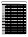
15
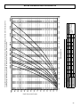
STANDARD PERFORMANCES - IR COOLING UNIT ONLY
Performance - Standard unit AB
MOD.
160.4
180.4
200.4
230.4
260.4
290.4
330.4
375.4
420.4
N:I
N:D
N:I
N:D
OUTDOOR AIR TEMPERATURE (°C D.B.)
30
35
40
N:I
N:D
N:I
N:D
N:I
N:D
185
190
196
201
207
212
218
223
204
210
216
222
228
234
240
247
229
236
243
250
256
263
270
277
263
270
278
286
293
301
309
317
293
301
310
319
328
337
345
355
333
343
353
363
372
382
392
403
372
382
394
405
416
427
438
450
423
435
448
461
473
486
498
512
471
484
499
513
527
541
555
570
33.5
33.8
34.1
34.5
34.9
35.2
35.5
35.9
37.9
38.2
38.6
39.1
39.5
39.8
40.2
40.6
43.4
43.8
44.3
44.8
45.2
45.7
46.1
46.6
49.9
50.4
50.9
51.4
51.9
52.5
53.0
53.5
54.3
54.8
55.4
56.0
56.6
57.1
57.7
58.2
62.9
63.5
64.2
64.9
65.5
66.2
66.8
67.5
70.9
71.5
72.3
73.1
73.8
74.5
75.3
76.0
78.6
79.3
80.1
81.0
81.8
82.6
83.5
84.3
89.8
90.7
91.6
92.6
93.5
94.4
95.4
96.3
173
177
183
188
193
198
203
209
191
196
202
207
213
219
224
230
214
220
227
233
239
246
252
259
245
252
259
267
274
281
288
296
274
281
290
298
306
314
322
331
311
320
329
338
348
357
366
376
347
357
367
378
388
398
409
420
395
406
418
430
442
453
465
478
440
452
465
479
492
505
518
532
38.5
38.9
39.3
39.7
40.1
40.5
40.9
41.3
43.6
44.0
44.5
44.9
45.4
45.8
46.3
46.7
50.0
50.4
51.0
51.5
52.0
52.6
53.1
53.6
57.4
57.9
58.5
59.2
59.8
60.4
61.0
61.5
62.5
63.1
63.7
64.4
65.1
65.7
66.4
67.0
72.4
73.1
73.8
74.7
75.4
76.2
76.9
77.6
81.5
82.3
83.1
84.1
84.9
85.7
86.6
87.4
90.4
91.3
92.2
93.2
94.2
95.1
96.0
97.0
103
104
105
107
108
109
110
111
163
168
173
178
182
187
192
197
180
185
191
196
202
207
212
218
203
208
214
220
226
232
238
245
232
238
245
252
259
266
273
280
259
266
274
282
289
297
305
313
294
302
311
320
329
338
346
356
328
338
347
357
367
377
386
397
374
384
395
407
418
429
440
452
416
428
440
453
465
477
490
503
TW
5
6
7
8
9
10
11
12
5
6
7
8
9
10
11
12
5
6
7
8
9
10
11
12
5
6
7
8
9
10
11
12
5
6
7
8
9
10
11
12
5
6
7
8
9
10
11
12
5
6
7
8
9
10
11
12
5
6
7
8
9
10
11
12
5
6
7
8
9
10
11
12
20
25
42.4
42.8
43.3
43.7
44.2
44.6
45.1
45.5
48.0
48.5
49.0
49.5
50.0
50.5
51.0
51.5
55.1
55.6
56.1
56.8
57.3
57.9
58.5
59.0
63.2
63.8
64.5
65.2
65.9
66.5
67.2
67.8
68.8
69.5
70.2
71.0
71.7
72.4
73.1
73.8
79.8
80.5
81.4
82.3
83.1
83.9
84.7
85.6
89.8
90.7
91.6
92.6
93.5
94.5
95.4
96.3
99.6
100.6
101.6
102.7
104
105
106
107
114
115
116
117
119
120
121
122
153
157
162
167
171
176
180
185
169
174
179
184
189
194
199
205
190
195
201
207
212
218
224
230
217
223
230
237
243
249
256
263
243
250
257
264
272
279
286
294
276
284
292
300
309
317
325
334
308
317
326
335
344
354
363
372
351
360
371
382
392
402
413
424
390
401
413
425
436
448
459
472
46.8
47.2
47.7
48.2
48.7
49.2
49.7
50.2
53.0
53.5
54.0
54.6
55.1
55.7
56.2
56.8
60.7
61.3
61.9
62.6
63.2
63.8
64.5
65.1
69.7
70.4
71.1
71.9
72.6
73.3
74.0
74.8
75.9
76.6
77.4
78.3
79.0
79.8
80.6
81.4
88.0
88.8
89.7
90.7
91.6
92.5
93.4
94.3
99.0
100.0
101.0
102.1
103.1
104
105
106
110
111
112
113
114
116
117
118
126
127
128
129
131
132
133
135
143
146
151
155
159
163
168
172
157
162
167
171
176
181
185
190
177
182
187
192
198
203
208
214
202
208
214
220
226
232
238
245
226
232
239
246
253
259
266
273
257
264
272
279
287
295
302
310
287
295
303
312
320
329
337
347
326
335
345
355
365
374
384
394
363
373
384
395
406
417
427
439
51.6
52.0
52.6
53.2
53.7
54.2
54.8
55.3
58.4
58.9
59.5
60.2
60.8
61.4
62.0
62.6
66.9
67.5
68.2
69.0
69.7
70.4
71.1
71.7
76.9
77.6
78.4
79.2
80.0
80.8
81.6
82.4
83.7
84.4
85.3
86.3
87.1
88.0
88.8
89.7
97.0
97.9
98.9
100.0
101.0
102.0
103
104
109
110
111
113
114
115
116
117
121
122
123
125
126
127
129
130
138
140
141
143
144
145
147
148
45
50
N:I
N:D
N:I
N:D
132
136
140
144
148
151
155
160
146
150
154
159
163
167
172
176
164
168
173
178
183
188
193
198
187
193
198
204
209
215
220
226
209
215
221
228
234
240
246
253
238
244
252
259
266
273
280
288
266
273
281
289
297
305
312
321
302
311
320
329
338
347
356
365
336
346
356
366
376
386
396
407
56.2
56.7
57.3
58.0
58.5
59.1
59.7
60.3
63.6
64.2
64.9
65.6
66.3
66.9
67.6
68.2
72.9
73.6
74.4
75.2
76.0
76.7
77.5
78.2
83.8
84.6
85.4
86.4
87.2
88.1
89.0
89.8
91.2
92.1
93.0
94.0
95.0
95.9
96.9
97.8
106
107
108
109
110
111
112
113
119
120
121
123
124
125
126
128
132
133
135
136
137
139
140
142
151
152
154
156
157
159
160
162
121
125
128
134
138
142
150
155
159
172
177
182
192
198
203
219
225
231
244
251
258
278
285
294
309
318
327
-
60.8
61.3
62.0
68.8
69.4
70.2
78.9
79.6
80.4
90.6
91.4
92.4
98.6
99.5
100.6
114
115
117
129
130
131
143
144
146
163
165
166
-
Tw= Outlet water temperature °C
N:I= Cooling capacity (kW).
N:D = Compressor power input (kW)
The standard performances refer to a 5°C temperature difference between the water entering and leaving the heat exchanger and to operation of the unit with all fans at
nominal or maximum speed. A 0.44 x 10⁻⁴ m2.:IRXOLQJIDFWRUKDVDOVREHHQFRQVLGHUHGZLWKWKHXQLWLQVWDOOHGDW]HURPHWHUVDERYHVHDOHYHO3E PEDU
16
STANDARD PERFORMANCES - IR COOLING UNIT ONLY
Performance - Low noise unit AS
MOD.
160.4
180.4
200.4
230.4
260.4
290.4
330.4
375.4
420.4
N:I
N:D
N:I
N:D
OUTDOOR AIR TEMPERATURE (°C D.B.)
30
35
40
N:I
N:D
N:I
N:D
N:I
N:D
178
183
188
194
199
204
210
215
196
202
208
214
219
225
231
237
220
226
233
240
246
253
259
266
252
259
267
274
282
289
297
305
282
290
298
307
315
323
332
341
320
328
338
348
357
367
376
386
357
367
378
389
399
410
420
432
406
418
430
442
454
466
478
491
452
465
478
492
505
519
532
546
36.1
36.5
36.8
37.3
37.6
38.0
38.4
38.7
40.9
41.3
41.7
42.2
42.6
43.0
43.4
43.9
46.9
47.4
47.9
48.4
48.9
49.4
49.8
50.3
53.9
54.4
54.9
55.6
56.1
56.7
57.2
57.8
58.7
59.2
59.8
60.5
61.1
61.7
62.3
62.9
68.0
68.6
69.3
70.1
70.8
71.5
72.2
72.9
76.5
77.2
78.0
78.8
79.6
80.4
81.2
82.0
84.9
85.7
86.6
87.5
88.4
89.3
90.2
91.0
96.8
97.7
98.7
99.8
101
102
103
104
166
171
176
181
186
191
196
201
183
188
194
199
205
210
216
221
206
211
217
224
230
236
242
249
235
242
249
256
263
270
277
285
263
270
278
286
294
302
310
318
298
307
316
324
333
342
351
361
333
343
353
363
373
383
392
403
379
390
401
413
424
435
446
458
422
434
446
459
472
484
496
510
41.6
42.0
42.4
42.9
43.3
43.7
44.2
44.6
47.1
47.5
48.0
48.5
49.0
49.5
50.0
50.5
54.0
54.5
55.1
55.7
56.2
56.8
57.4
57.9
62.0
62.6
63.2
63.9
64.6
65.2
65.8
66.5
67.5
68.1
68.8
69.6
70.3
71.0
71.7
72.4
78.2
79.0
79.8
80.6
81.5
82.3
83.1
83.9
88.0
88.8
89.7
90.7
91.6
92.5
93.4
94.4
97.7
98.6
99.6
101
102
103
104
105
111
112
114
115
116
117
118
119
157
162
166
171
176
180
185
190
173
178
183
188
194
199
204
209
194
200
206
211
217
223
229
235
223
229
235
242
249
255
262
269
249
256
263
271
278
285
293
301
282
290
298
307
315
324
332
341
315
324
334
343
352
362
371
381
359
369
379
390
401
411
422
433
399
410
422
434
446
458
469
482
TW
5
6
7
8
9
10
11
12
5
6
7
8
9
10
11
12
5
6
7
8
9
10
11
12
5
6
7
8
9
10
11
12
5
6
7
8
9
10
11
12
5
6
7
8
9
10
11
12
5
6
7
8
9
10
11
12
5
6
7
8
9
10
11
12
5
6
7
8
9
10
11
12
20
25
45.8
46.2
46.7
47.2
47.7
48.2
48.6
49.1
51.9
52.3
52.9
53.5
54.0
54.5
55.1
55.6
59.5
60.1
60.7
61.3
62.0
62.6
63.2
63.8
68.3
69.0
69.7
70.4
71.1
71.8
72.5
73.2
74.4
75.1
75.8
76.7
77.4
78.2
79.0
79.7
86.2
87.0
87.9
88.9
89.7
90.6
91.5
92.4
97.0
97.9
98.9
100
101
102
103
104
108
109
110
111
112
113
114
115
123
124
125
127
128
129
130
132
147
152
156
160
165
169
174
178
163
167
172
177
182
187
191
197
182
188
193
198
204
209
215
221
209
215
221
227
234
240
246
253
234
240
247
254
261
268
275
282
265
272
280
288
296
304
311
320
296
304
313
322
331
340
348
358
337
346
356
366
376
386
396
407
374
385
396
407
418
430
441
452
50.5
51.0
51.5
52.1
52.6
53.1
53.6
54.2
57.2
57.7
58.3
58.9
59.5
60.1
60.7
61.3
65.6
66.2
66.9
67.6
68.3
69.0
69.7
70.3
75.3
76.0
76.8
77.6
78.4
79.2
80.0
80.8
82.0
82.8
83.6
84.5
85.4
86.2
87.1
87.9
95.0
95.9
96.9
98.0
99.0
99.9
101
102
107
108
109
110
111
112
114
115
119
120
121
122
124
125
126
127
135
137
138
140
141
142
144
145
137
141
145
149
153
157
161
166
151
155
160
165
169
174
178
183
170
174
180
185
190
195
200
205
194
200
206
211
217
223
229
235
217
223
230
236
243
249
256
263
246
253
261
268
275
283
290
298
275
283
291
299
308
316
324
333
313
322
331
341
350
359
368
378
348
358
368
379
389
400
410
421
55.7
56.2
56.8
57.4
58.0
58.5
59.1
59.7
63.0
63.6
64.3
65.0
65.6
66.3
66.9
67.6
72.3
73.0
73.7
74.6
75.3
76.0
76.8
77.5
83.0
83.8
84.6
85.6
86.4
87.3
88.2
89.0
90.4
91.2
92.1
93.2
94.1
95.0
96.0
96.9
105
106
107
108
109
110
111
112
118
119
120
121
123
124
125
126
131
132
133
135
136
138
139
140
149
151
152
154
155
157
158
160
45
50
N:I
N:D
N:I
N:D
127
131
134
138
142
146
150
154
140
144
148
152
157
161
165
169
157
162
166
171
176
180
185
190
180
185
190
196
201
207
212
218
201
207
213
219
225
231
237
243
228
234
241
248
255
262
268
276
255
262
270
277
285
293
300
308
290
298
307
315
324
333
341
351
323
332
341
351
361
370
380
390
60.7
61.3
61.9
62.6
63.2
63.8
64.4
65.1
68.7
69.3
70.1
70.8
71.5
72.2
73.0
73.7
78.8
79.6
80.4
81.3
82.1
82.9
83.7
84.5
90.5
91.4
92.3
93.3
94.2
95.2
96.1
97.0
98.5
99.4
100.5
101.6
102.6
103.6
104.6
105.6
114
115
116
118
119
120
121
122
128
130
131
132
134
135
136
138
143
144
145
147
148
150
151
153
163
164
166
168
169
171
173
174
117
120
123
129
132
136
144
148
153
165
170
175
185
190
196
210
215
222
234
241
248
266
274
282
296
305
313
-
65.6
66.2
66.9
74.3
75.0
75.7
85.2
86.0
86.9
97.9
98.8
99.8
107
108
109
123
125
126
139
140
142
154
156
157
176
177
179
-
Tw= Outlet water temperature °C
N:I= Cooling capacity (kW).
N:D = Compressor power input (kW)
The standard performances refer to a 5°C temperature difference between the water entering and leaving the heat exchanger and to operation of the unit with all fans at
nominal or maximum speed. A 0.44 x 10⁻⁴ m2.:IRXOLQJIDFWRUKDVDOVREHHQFRQVLGHUHGZLWKWKHXQLWLQVWDOOHGDW]HURPHWHUVDERYHVHDOHYHO3E PEDU
17
STANDARD PERFORMANCES - IR COOLING UNIT ONLY
Performance - Extra low noise unit AX
MOD.
TW
20
N:I
25
N:D
N:I
N:D
OUTDOOR AIR TEMPERATURE (°C D.B.)
30
35
40
N:I
N:D
N:I
N:D
N:I
N:D
45
N:I
50
N:D
N:I
N:D
5
174
37.1
162
42.7
153
47.1
144
51.9
134
57.2
124
62.3
114
67.4
6
178
37.5
166
43.1
157
47.5
148
52.4
137
57.7
127
62.9
117
68.0
7
184
37.8
171
43.5
162
48.0
152
52.9
141
58.3
131
63.6
120
68.7
8
189
38.3
176
44.0
167
48.5
156
53.5
145
59.0
135
64.3
9
194
38.6
181
44.5
171
49.0
161
54.0
149
59.5
138
64.9
10
199
39.0
186
44.9
176
49.5
165
54.6
153
60.1
142
65.6
11
204
39.4
191
45.4
180
50.0
169
55.1
157
60.7
146
66.2
12
210
39.8
196
45.8
185
50.5
174
55.6
162
61.3
150
66.8
5
192
42.0
179
48.4
169
53.3
159
58.7
148
64.7
137
70.6
126
76.3
6
197
42.4
184
48.8
174
53.8
163
59.3
152
65.4
141
71.3
129
77.0
7
203
42.9
189
49.3
179
54.3
168
59.9
156
66.0
145
72.0
133
77.8
8
209
43.3
195
49.9
184
54.9
173
60.6
161
66.8
149
72.8
9
214
43.8
200
50.4
189
55.5
178
61.2
165
67.4
153
73.5
10
220
44.2
205
50.9
194
56.0
182
61.8
170
68.1
157
74.2
11
226
44.6
211
51.4
199
56.6
187
62.4
174
68.8
161
75.0
12
232
45.1
216
51.9
205
57.1
192
63.0
179
69.4
165
75.7
5
216
48.2
201
55.5
190
61.1
179
67.4
166
74.3
154
81.0
141
87.5
6
222
48.7
207
56.0
196
61.7
184
68.0
171
75.0
158
81.7
145
88.4
7
228
49.2
213
56.6
201
62.3
189
68.7
176
75.7
163
82.6
150
89.3
8
235
49.7
219
57.2
207
63.0
194
69.5
181
76.6
167
83.5
9
241
50.2
225
57.8
213
63.6
200
70.2
186
77.3
172
84.3
10
247
50.7
231
58.3
218
64.3
205
70.9
191
78.1
177
85.1
11
254
51.2
237
58.9
224
64.9
210
71.5
196
78.9
181
86.0
12
261
51.7
243
59.5
230
65.5
216
72.2
201
79.6
186
86.8
5
247
55.4
230
63.7
218
70.2
204
77.4
190
85.3
176
93.0
162
101
6
253
55.9
237
64.3
224
70.8
210
78.1
195
86.1
181
93.9
166
101
7
261
56.5
243
65.0
230
71.6
216
78.9
201
87.0
186
94.8
171
103
8
268
57.1
250
65.7
237
72.4
222
79.8
207
87.9
191
95.9
9
276
57.6
257
66.3
243
73.1
228
80.6
212
88.8
197
96.8
10
283
58.2
264
67.0
250
73.8
234
81.4
218
89.7
202
97.8
11
290
58.8
271
67.6
256
74.5
240
82.2
224
90.6
207
98.7
12
298
59.4
278
68.3
263
75.3
247
83.0
230
91.4
213
99.7
5
276
60.3
258
69.3
244
76.4
229
84.2
213
92.8
197
101
181
109
6
284
60.8
265
70.0
251
77.1
235
85.0
219
93.7
203
102
186
110
7
292
61.5
273
70.7
258
77.9
242
85.9
225
94.7
209
103
192
112
8
300
62.1
280
71.5
265
78.8
249
86.8
232
95.7
214
104
9
309
62.8
288
72.2
272
79.6
256
87.7
238
96.7
220
105
10
317
63.4
296
72.9
280
80.4
262
88.6
244
97.6
226
106
11
325
64.0
303
73.6
287
81.1
269
89.5
250
98.6
232
107
12
334
64.6
312
74.4
295
81.9
277
90.3
257
99.6
238
109
5
313
69.9
292
80.4
276
88.6
259
97.7
241
108
223
117
205
127
6
321
70.5
300
81.2
284
89.4
266
98.6
248
109
229
118
211
128
7
331
71.3
309
82.0
292
90.3
274
99.6
255
110
236
120
217
129
8
340
72.0
318
82.9
300
91.3
282
101
262
111
243
121
9
350
72.8
326
83.7
309
92.3
290
102
269
112
249
122
10
359
73.5
335
84.6
317
93.2
297
103
277
113
256
123
11
368
74.2
343
85.4
325
94.1
305
104
284
114
263
125
12
378
74.9
353
86.2
334
95.0
313
105
291
115
270
126
5
349
78.6
326
90.4
308
99.6
289
110
269
121
249
132
229
143
6
359
79.3
335
91.3
317
101
297
111
277
122
256
133
235
144
7
369
80.1
345
92.2
326
102
306
112
285
123
264
135
242
146
8
380
81.0
355
93.2
335
103
315
113
293
125
271
136
9
390
81.8
364
94.2
345
104
323
114
301
126
279
137
10
401
82.6
374
95.1
354
105
332
116
309
127
286
139
11
411
83.5
384
96.0
363
106
340
117
317
129
293
140
12
422
84.3
394
97.0
373
107
350
118
325
130
301
142
5
398
87.0
372
100
352
110
330
122
307
134
284
146
261
158
6
409
87.8
382
101
361
111
339
123
316
135
292
147
268
159
7
421
88.7
393
102
372
112
349
124
325
137
301
149
276
161
8
433
89.7
404
103
382
114
359
125
334
138
309
151
9
445
90.6
416
104
393
115
369
127
343
140
318
152
10
457
91.5
427
105
403
116
379
128
352
141
326
154
11
469
92.4
437
106
414
117
388
129
361
142
335
155
12
481
93.3
449
107
425
118
399
130
371
144
344
157
5
443
99.6
413
115
391
126
367
139
341
153
316
167
290
181
6
455
101
425
116
402
127
377
141
351
155
325
169
298
183
7
468
102
437
117
413
129
388
142
361
157
334
171
307
184
8
482
103
450
118
425
130
399
144
371
158
344
173
9
495
104
462
119
437
132
410
145
381
160
353
174
10
508
105
474
121
448
133
421
146
392
161
363
176
11
521
106
486
122
460
134
432
148
402
163
372
178
12
535
107
500
123
472
135
443
149
412
165
382
179
Tw= Outlet water temperature °C
N:I= Cooling capacity (kW).
N:D = Compressor power input (kW)
The standard performances refer to a 5°C temperature difference between the water entering and leaving the heat exchanger and to operation of the unit with all fans at
nominal or maximum speed. A 0.44 x 10 -4 m2.:IRXOLQJIDFWRUKDVDOVREHHQFRQVLGHUHGZLWKWKHXQLWLQVWDOOHGDW]HURPHWHUVDERYHVHDOHYHO3E PEDU
160.4
180.4
200.4
230.4
260.4
290.4
330.4
375.4
420.4
18
STANDARD PERFORMANCES - IP HEAT PUMP UNITS
Performances in cooling mode - Standard Unit AB
MOD.
160.4
180.4
200.4
230.4
260.4
290.4
330.4
375.4
420.4
N:I
N:D
N:I
N:D
OUTDOOR AIR TEMPERATURE (°C D.B.)
30
35
40
N:I
N:D
N:I
N:D
N:I
N:D
177
182
187
192
198
203
208
214
196
202
208
214
219
225
231
237
221
228
234
241
247
254
261
268
248
255
262
269
277
284
291
299
281
289
297
305
314
322
330
339
317
326
336
345
355
364
373
383
356
366
377
387
398
409
419
430
411
422
435
447
459
471
483
497
458
470
484
498
512
525
539
553
33.0
33.3
33.6
34.0
34.3
34.7
35.0
35.4
37.4
37.7
38.1
38.6
38.9
39.3
39.7
40.1
42.6
43.0
43.4
43.9
44.3
44.8
45.2
45.7
48.8
49.2
49.7
50.3
50.8
51.3
51.8
52.3
54.0
54.5
55.0
55.6
56.2
56.7
57.3
57.9
62.0
62.6
63.2
63.9
64.6
65.2
65.9
66.5
70.2
70.8
71.5
72.3
73.1
73.8
74.5
75.2
77.9
78.6
79.4
80.3
81.1
81.9
82.7
83.5
87.7
88.5
89.4
90.4
91.3
92.2
93.1
94.0
165
170
175
180
185
189
194
200
183
188
194
199
205
210
216
221
207
212
219
225
231
237
243
250
231
238
245
251
258
265
272
279
262
269
277
285
293
301
308
317
296
304
313
322
331
340
348
358
332
342
352
362
372
381
391
402
384
394
406
417
429
440
451
464
427
439
452
465
477
490
503
516
37.9
38.3
38.7
39.1
39.5
39.9
40.3
40.7
43.0
43.4
43.9
44.4
44.8
45.3
45.7
46.1
49.0
49.5
50.0
50.5
51.0
51.5
52.0
52.5
56.1
56.6
57.2
57.8
58.4
59.0
59.6
60.2
62.1
62.7
63.3
64.0
64.6
65.3
65.9
66.6
71.4
72.0
72.8
73.6
74.3
75.0
75.8
76.5
80.7
81.5
82.3
83.2
84.1
84.9
85.7
86.6
89.6
90.5
91.4
92.4
93.3
94.2
95.2
96.1
101
102
103
104
105
106
107
108
156
160
165
170
175
179
184
189
173
178
183
188
194
199
204
209
195
201
207
213
218
224
230
236
219
225
231
238
244
251
257
264
248
255
262
270
277
284
292
300
280
288
296
305
313
321
330
338
314
323
332
342
351
361
370
380
363
373
384
394
405
416
427
438
404
415
427
439
452
463
475
488
TW
5
6
7
8
9
10
11
12
5
6
7
8
9
10
11
12
5
6
7
8
9
10
11
12
5
6
7
8
9
10
11
12
5
6
7
8
9
10
11
12
5
6
7
8
9
10
11
12
5
6
7
8
9
10
11
12
5
6
7
8
9
10
11
12
5
6
7
8
9
10
11
12
20
25
41.8
42.2
42.6
43.1
43.5
44.0
44.4
44.8
47.4
47.9
48.3
48.9
49.4
49.9
50.3
50.8
54.0
54.5
55.1
55.7
56.2
56.8
57.3
57.9
61.8
62.4
63.0
63.7
64.4
65.0
65.6
66.3
68.4
69.0
69.7
70.5
71.2
71.9
72.6
73.3
78.6
79.4
80.2
81.1
81.9
82.7
83.5
84.3
88.9
89.8
90.7
91.7
92.6
93.5
94.5
95.4
98.7
99.7
101
102
103
104
105
106
111
112
113
115
116
117
118
119
147
151
155
159
164
168
172
177
163
167
172
177
182
187
191
197
183
189
194
199
205
210
216
222
205
211
217
223
229
235
241
248
233
239
246
253
260
267
274
281
263
270
278
286
294
302
309
318
295
303
312
321
330
338
347
356
340
350
360
370
380
390
400
411
379
390
401
412
424
435
446
458
46.1
46.5
47.0
47.5
48.0
48.5
48.9
49.4
52.3
52.8
53.3
53.9
54.4
55.0
55.5
56.0
59.5
60.1
60.7
61.4
62.0
62.6
63.2
63.8
68.2
68.8
69.5
70.3
71.0
71.7
72.4
73.1
75.4
76.1
76.9
77.7
78.5
79.3
80.1
80.9
86.7
87.5
88.4
89.4
90.3
91.2
92.1
93.0
98.1
99.0
100
101
102
103
104
105
109
110
111
112
113
114
116
117
123
124
125
126
128
129
130
131
136
140
144
148
152
156
160
165
151
155
160
165
169
174
178
183
171
175
180
186
191
196
201
206
191
196
202
208
213
219
225
231
216
222
229
235
242
248
255
262
245
251
259
266
273
281
288
296
274
282
290
299
307
315
323
332
317
325
335
344
354
363
373
383
353
363
373
384
394
405
415
426
50.8
51.3
51.8
52.4
52.9
53.4
54.0
54.5
57.6
58.2
58.7
59.4
60.0
60.6
61.2
61.8
65.6
66.2
66.9
67.6
68.3
69.0
69.7
70.4
75.1
75.8
76.6
77.5
78.2
79.0
79.8
80.6
83.1
83.9
84.8
85.7
86.6
87.4
88.3
89.1
95.6
96.4
97.4
98.5
99.5
100
101
102
108
109
110
111
113
114
115
116
120
121
122
124
125
126
127
129
135
136
138
139
141
142
143
145
45
50
N:I
N:D
N:I
N:D
126
130
134
137
141
145
149
153
140
144
148
152
157
161
165
169
158
162
167
172
177
181
186
191
177
182
187
192
198
203
208
214
200
206
212
218
224
230
236
242
226
233
240
246
253
260
266
274
254
261
269
276
284
292
299
307
293
301
310
319
328
336
345
354
327
336
346
355
365
375
384
395
55.4
55.9
56.5
57.1
57.7
58.2
58.8
59.4
62.8
63.4
64.0
64.8
65.4
66.1
66.7
67.4
71.5
72.2
72.9
73.7
74.5
75.2
76.0
76.7
81.9
82.7
83.5
84.4
85.3
86.1
87.0
87.8
90.6
91.5
92.4
93.4
94.4
95.3
96.2
97.2
104
105
106
107
108
110
111
112
118
119
120
121
123
124
125
126
131
132
133
135
136
138
139
140
147
149
150
152
153
155
156
158
116
119
123
129
132
136
145
149
154
162
167
172
184
189
195
208
214
220
233
240
247
269
277
285
300
308
317
-
59.9
60.4
61.1
67.9
68.5
69.3
77.3
78.1
78.9
88.6
89.4
90.3
98.0
98.9
99.9
113
114
115
127
129
130
141
143
144
159
161
162
-
Tw= Outlet water temperature °C
N:I= Cooling capacity (kW).
N:D = Compressor power input (kW)
The standard performances refer to a 5°C temperature difference between the water entering and leaving the heat exchanger and to operation of the unit with all fans at
-4
2
nominal or maximum speed. A 0.44 x 10 m .:IRXOLQJIDFWRUKDVDOVREHHQFRQVLGHUHGZLWKWKHXQLWLQVWDOOHGDW]HURPHWHUVDERYHVHDOHYHO3E PEDU
19
STANDARD PERFORMANCES - IP HEAT PUMP UNITS
Performances in heating mode - Standard Unit AB
MOD.
160.4
180.4
200.4
230.4
260.4
290.4
330.4
375.4
420.4
N:W
N:D
N:W
N:D
OUTDOOR AIR TEMPERATURE (°C D.B.)
2
6
9
N:W
N:D
N:W
N:D
N:W
N:D
128
34.2
147
34.4
161
34.9
171
35.1
183
35.5
196
35.9
210
36.3
128
37.9
146
38.2
160
38.7
170
38.9
182
39.4
195
39.8
209
40.3
127
42.2
145
42.4
159
43.0
169
43.3
181
43.8
194
44.3
208
44.8
126
46.9
144
47.2
158
47.8
168
48.1
180
48.7
193
49.2
206
49.8
125
52.1
143
52.4
157
53.2
167
53.5
179
54.1
191
54.7
205
55.3
144
39.2
165
39.5
181
40.0
192
40.2
206
40.7
221
41.2
236
41.6
144
43.5
165
43.7
180
44.3
191
44.6
205
45.1
219
45.6
235
46.1
143
48.3
164
48.6
179
49.3
190
49.6
204
50.2
218
50.7
233
51.3
142
53.7
162
54.0
178
54.8
189
55.1
203
55.7
217
56.4
232
57.0
141
59.7
161
60.1
176
60.9
188
61.3
201
62.0
215
62.7
230
63.4
163
44.8
186
45.0
204
45.7
217
45.9
233
46.5
249
47.0
266
47.5
162
49.6
185
49.9
203
50.6
216
50.9
231
51.5
247
52.1
265
52.7
161
55.2
184
55.5
202
56.3
214
56.6
230
57.3
246
57.9
263
58.6
160
61.3
183
61.7
200
62.5
213
62.9
228
63.6
244
64.4
261
65.1
159
68.2
182
68.6
199
69.5
212
69.9
227
70.7
243
71.5
259
72.4
182
51.0
208
51.4
228
52.1
242
52.4
260
53.0
278
53.6
297
54.2
181
56.6
207
56.9
227
57.7
241
58.0
259
58.7
276
59.4
296
60.0
180
62.9
206
63.3
225
64.1
240
64.5
257
65.3
275
66.0
294
66.8
179
69.9
205
70.3
224
71.3
238
71.7
255
72.5
273
73.4
292
74.2
177
77.7
203
78.2
222
79.3
236
79.7
253
80.6
271
81.6
290
82.5
206
56.2
236
56.6
258
57.4
275
57.7
295
58.4
315
59.0
337
59.7
205
62.3
235
62.7
257
63.6
273
63.9
293
64.7
314
65.4
335
66.1
204
69.3
234
69.7
256
70.7
272
71.1
292
71.9
312
72.7
334
73.6
203
77.0
232
77.5
254
78.5
270
79.0
290
79.9
310
80.8
331
81.7
201
85.6
231
86.1
252
87.3
268
87.8
288
88.8
307
89.9
329
90.9
233
64.4
267
64.7
292
65.6
310
66.0
333
66.8
356
67.5
381
68.3
232
71.3
266
71.7
290
72.7
309
73.2
331
74.0
354
74.8
379
75.7
230
79.3
264
79.8
289
80.9
307
81.3
329
82.3
352
83.2
377
84.2
229
88.1
262
88.7
287
89.9
305
90.4
327
91.4
350
92.5
374
93.5
227
98.0
260
98.6
285
99.9
303
101
325
102
347
103
372
104
261
72.6
299
73.1
327
74.1
348
74.5
373
75.3
399
76.2
427
77.1
260
80.5
298
81.0
326
82.1
346
82.5
371
83.5
397
84.5
425
85.4
258
89.5
296
90.0
324
91.2
344
91.8
369
92.8
395
93.9
422
95.0
257
99.4
294
100
322
101
342
102
367
103
392
104
420
106
255
111
292
111
319
113
340
113
364
115
389
116
417
117
299
81.2
342
81.6
374
82.8
398
83.2
427
84.2
456
85.2
488
86.1
297
295
293
89.9
100
111
340
338
336
90.5
101
112
372
370
368
91.7
102
113
396
394
391
92.3
103
114
425
422
419
93.3
104
115
454
451
448
94.4
105
117
486
483
480
95.5
106
118
291
124
334
124
365
126
388
127
416
128
445
130
476
131
332
91.8
381
92.4
416
93.7
443
94.2
475
95.3
508
96.4
543
97.5
330
102
379
102
414
104
441
104
472
106
505
107
540
108
329
113
377
114
412
115
438
116
470
117
502
119
537
120
326
126
374
127
409
128
435
129
467
130
499
132
534
133
324
140
371
141
406
143
432
143
463
145
495
147
530
148
TW
30
35
40
45
50
30
35
40
45
50
30
35
40
45
50
30
35
40
45
50
30
35
40
45
50
30
35
40
45
50
30
35
40
45
50
30
35
40
45
50
30
35
40
45
50
-6
-2
12
15
N:W
N:D
N:W
N:D
Tw= Outlet water temperature °C
N:W= Heating capacity (kW).
N:D = Compressor power input (kW)
The standard performances refer to a 5°C temperature difference between the water entering and leaving the plate-type heat exchanger, outdoor air with 87% relative
humidity and to operation of the unit with all the fans to top speed. A 0.44 x 10⁻⁴ m2.:IRXOLQJIDFWRUKDVDOVREHHQFRQVLGHUHGZLWKWKHXQLWLQVWDOOHGDW]HURPHWHUVDERYH
sea level (Pb = 1013mbar).
NOTE
For air temperatures of less than 7°C, the heating capacity is declared without considering the effect of the defrosting, strictly correlated with the humidity in the outdoor air.
20
STANDARD PERFORMANCES - IP HEAT PUMP UNITS
Performances in cooling mode - Low noise Unit AS
MOD.
TW
20
N:I
25
N:D
N:I
N:D
OUTDOOR AIR TEMPERATURE (°C D.B.)
30
35
40
N:I
N:D
N:I
N:D
N:I
N:D
45
N:I
50
N:D
N:I
N:D
5
170
35.6
159
41.0
150
45.2
141
49.8
131
54.9
121
59.9
112
64.7
6
175
36.0
163
41.4
154
45.6
145
50.3
135
55.4
125
60.4
115
65.3
7
180
36.3
168
41.8
159
46.1
149
50.8
139
56.0
128
61.0
118
66.0
8
185
36.7
173
42.3
163
46.6
153
51.4
143
56.6
132
61.7
9
190
37.1
177
42.7
168
47.1
157
51.9
146
57.2
136
62.3
10
195
37.5
182
43.1
172
47.5
162
52.4
150
57.7
139
63.0
11
200
37.9
187
43.6
177
48.0
166
52.9
154
58.3
143
63.6
12
206
38.2
192
44.0
181
48.5
170
53.4
158
58.9
147
64.2
5
188
40.4
176
46.5
166
51.2
156
56.5
145
62.3
134
67.9
123
73.4
6
194
40.8
181
46.9
171
51.7
160
57.0
149
62.8
138
68.5
127
74.1
7
199
41.2
186
47.4
176
52.2
165
57.6
154
63.5
142
69.2
131
74.8
8
205
41.7
191
47.9
181
52.8
170
58.2
158
64.2
146
70.0
9
210
42.1
196
48.4
186
53.3
174
58.8
162
64.8
150
70.7
10
216
42.5
202
48.9
191
53.9
179
59.4
167
65.5
154
71.4
11
222
42.9
207
49.4
196
54.4
184
60.0
171
66.1
158
72.1
12
228
43.3
212
49.9
201
54.9
189
60.6
175
66.8
162
72.8
5
212
46.0
198
53.0
187
58.3
176
64.3
164
70.9
152
77.3
139
83.6
6
218
46.5
204
53.5
193
58.9
181
64.9
168
71.6
156
78.0
143
84.4
7
225
46.9
210
54.0
198
59.5
186
65.6
173
72.3
160
78.8
147
85.2
8
231
47.5
216
54.6
204
60.2
191
66.3
178
73.1
165
79.7
9
237
47.9
221
55.1
209
60.8
197
67.0
183
73.8
169
80.5
10
244
48.4
227
55.7
215
61.4
202
67.7
188
74.6
174
81.3
11
250
48.9
233
56.2
220
62.0
207
68.3
193
75.3
178
82.1
12
257
49.4
239
56.8
226
62.6
213
69.0
198
76.0
183
82.9
5
237
52.7
222
60.6
210
66.8
197
73.6
183
81.2
169
88.5
156
95.7
6
244
53.2
228
61.2
215
67.4
202
74.3
188
81.9
174
89.3
160
96.6
7
251
53.7
234
61.8
222
68.1
208
75.1
194
82.8
179
90.2
165
97.6
8
258
54.3
241
62.5
228
68.9
214
75.9
199
83.7
184
91.2
9
265
54.9
248
63.1
234
69.6
220
76.7
204
84.5
189
92.2
10
272
55.4
254
63.8
240
70.2
226
77.5
210
85.4
194
93.1
11
279
56.0
261
64.4
247
70.9
231
78.2
215
86.2
199
94.0
12
287
56.5
268
65.0
253
71.6
238
79.0
221
87.0
205
94.9
5
269
58.3
251
67.1
238
73.9
223
81.5
208
89.8
192
97.9
177
106
6
277
58.9
258
67.7
244
74.6
229
82.3
213
90.7
198
98.8
182
107
7
285
59.5
266
68.4
251
75.4
236
83.1
220
91.6
203
99.9
187
108
8
293
60.1
273
69.2
259
76.2
243
84.0
226
92.6
209
101
9
301
60.7
281
69.9
266
77.0
249
84.9
232
93.5
215
102
10
309
61.3
288
70.5
273
77.7
256
85.7
238
94.5
221
103
11
317
61.9
296
71.2
280
78.5
263
86.5
244
95.4
226
104
12
326
62.5
304
71.9
287
79.3
270
87.4
251
96.3
232
105
5
305
67.0
284
77.1
269
84.9
252
93.7
235
103
218
113
200
122
6
313
67.6
292
77.8
276
85.7
259
94.5
241
104
224
114
205
123
7
322
68.3
301
78.6
285
86.6
267
95.5
248
105
230
115
211
124
8
331
69.1
309
79.5
293
87.6
275
96.6
255
106
237
116
9
341
69.8
318
80.3
301
88.5
282
97.5
262
107
243
117
10
350
70.5
326
81.1
309
89.3
290
98.5
269
109
250
118
11
359
71.2
335
81.9
316
90.2
297
99.5
276
110
256
120
12
368
71.9
344
82.7
325
91.1
305
100
284
111
263
121
5
342
75.8
320
87.2
302
96.1
284
106
264
117
244
127
225
138
6
352
76.5
328
88.0
311
97.0
291
107
271
118
251
128
231
139
7
362
77.3
338
88.9
320
98.0
300
108
279
119
259
130
237
140
8
372
78.1
348
89.9
329
99.0
309
109
287
120
266
131
9
383
78.9
357
90.8
338
100
317
110
295
122
273
133
10
393
79.7
367
91.7
347
101
325
111
303
123
280
134
11
403
80.5
376
92.6
356
102
334
112
310
124
288
135
12
414
81.3
386
93.5
365
103
343
114
319
125
295
136
5
395
84.2
369
96.9
349
107
327
118
304
130
282
141
259
153
6
406
85.0
379
97.8
358
108
336
119
313
131
290
143
266
154
7
418
85.9
390
98.8
369
109
346
120
322
132
298
144
274
156
8
430
86.8
401
99.9
379
110
356
121
331
134
307
146
9
441
87.7
412
101
390
111
366
123
340
135
315
147
10
453
88.5
423
102
400
112
375
124
349
136
323
149
11
465
89.4
434
103
410
113
385
125
358
138
332
150
12
477
90.3
446
104
421
114
395
126
368
139
341
152
5
439
94.7
410
109
388
120
364
132
339
146
314
159
288
172
6
452
95.6
422
110
399
121
374
134
348
147
322
161
296
174
7
465
96.6
434
111
410
122
385
135
358
149
332
162
305
175
8
478
97.7
446
112
422
124
396
136
368
150
341
164
9
491
98.6
458
113
434
125
407
138
379
152
351
166
10
504
99.6
471
115
445
126
418
139
389
153
360
167
11
517
101
483
116
456
128
428
141
398
155
369
169
12
531
102
496
117
469
129
440
142
409
156
379
171
Tw= Outlet water temperature °C
N:I= Cooling capacity (kW).
N:D = Compressor power input (kW)
The standard performances refer to a 5°C temperature difference between the water entering and leaving the heat exchanger and to operation of the unit with all fans at
nominal or maximum speed. A 0.44 x 10⁻⁴ m2.:IRXOLQJIDFWRUKDVDOVREHHQFRQVLGHUHGZLWKWKHXQLWLQVWDOOHGDW]HURPHWHUVDERYHVHDOHYHO3E PEDU
160.4
180.4
200.4
230.4
260.4
290.4
330.4
375.4
420.4
21
STANDARD PERFORMANCES - IP HEAT PUMP UNITS
Performances in heating mode - Low noise Unit AS
MOD.
160.4
180.4
200.4
230.4
260.4
290.4
330.4
375.4
420.4
N:W
N:D
N:W
N:D
OUTDOOR AIR TEMPERATURE (°C D.B.)
2
6
9
N:W
N:D
N:W
N:D
N:W
N:D
123
32.5
141
32.7
154
33.2
164
33.4
176
33.8
188
34.1
201
34.5
122
36.1
140
36.3
153
36.8
163
37.0
175
37.4
187
37.8
200
38.3
122
40.1
139
40.3
152
40.9
162
41.1
174
41.6
186
42.1
199
42.5
121
44.6
138
44.8
151
45.4
161
45.7
173
46.2
185
46.8
197
47.3
120
49.5
137
49.8
150
50.5
160
50.8
171
51.4
183
52.0
196
52.6
138
37.2
158
37.5
173
38.0
184
38.2
198
38.6
211
39.1
226
39.5
138
41.3
158
41.5
172
42.1
183
42.3
197
42.8
210
43.3
225
43.8
137
45.9
157
46.2
171
46.8
182
47.1
195
47.6
209
48.1
224
48.7
136
51.0
156
51.3
170
52.0
181
52.3
194
52.9
208
53.5
222
54.1
135
56.7
155
57.0
169
57.8
180
58.1
193
58.8
206
59.5
220
60.2
156
42.6
179
42.8
195
43.4
208
43.7
223
44.2
238
44.7
255
45.2
155
47.2
178
47.5
194
48.1
207
48.4
222
49.0
237
49.5
253
50.1
154
52.5
177
52.8
193
53.5
205
53.8
220
54.4
236
55.1
252
55.7
153
58.3
175
58.6
192
59.5
204
59.8
219
60.5
234
61.2
250
61.9
152
64.8
174
65.2
190
66.1
203
66.5
217
67.3
232
68.0
248
68.8
174
48.5
200
48.8
218
49.4
232
49.7
249
50.3
266
50.9
285
51.5
173
53.7
199
54.0
217
54.8
231
55.1
248
55.7
265
56.4
283
57.0
172
59.7
197
60.1
216
60.9
230
61.3
246
62.0
263
62.7
282
63.4
171
66.4
196
66.8
214
67.7
228
68.1
245
68.9
261
69.7
280
70.5
170
73.8
195
74.3
213
75.3
226
75.7
243
76.6
260
77.5
278
78.3
198
53.5
227
53.8
248
54.5
264
54.8
283
55.5
302
56.1
323
56.7
197
59.3
226
59.6
247
60.4
262
60.8
281
61.5
301
62.2
322
62.9
196
65.9
224
66.3
245
67.2
261
67.6
280
68.4
299
69.1
320
69.9
194
73.2
223
73.7
244
74.7
259
75.1
278
76.0
297
76.8
318
77.7
193
81.4
221
81.9
242
83.0
257
83.5
276
84.5
295
85.4
315
86.4
224
61.2
256
61.5
280
62.4
298
62.7
320
63.5
342
64.2
366
64.9
223
67.8
255
68.2
279
69.1
297
69.5
318
70.3
340
71.1
364
71.9
221
75.4
254
75.8
277
76.8
295
77.3
316
78.2
338
79.1
362
80.0
220
83.7
252
84.2
276
85.4
293
85.9
314
86.9
336
87.9
359
88.9
218
93.1
250
93.7
274
94.9
291
95.5
312
96.6
334
97.7
357
98.8
250
69.1
287
69.5
314
70.4
334
70.8
358
71.7
383
72.5
410
73.3
249
76.5
286
77.0
312
78.0
332
78.5
356
79.4
381
80.3
407
81.2
248
85.1
284
85.6
311
86.8
330
87.3
354
88.3
379
89.3
405
90.3
246
94.6
282
95.1
308
96.4
328
97.0
352
98.1
376
99.2
402
100
244
105
280
106
306
107
326
108
349
109
373
110
400
112
286
76.9
328
77.3
359
78.4
382
78.9
409
79.8
438
80.7
468
81.6
285
283
281
85.2
94.7
105
327
325
322
85.7
95.3
106
357
355
353
86.9
96.6
107
380
378
375
87.4
97.2
108
407
405
402
88.4
98.3
109
435
433
430
89.4
99.4
110
466
463
460
90.4
101
112
279
117
320
118
350
119
372
120
399
121
427
123
457
124
319
87.6
366
88.1
400
89.3
426
89.8
456
90.9
488
91.9
522
92.9
318
97.0
364
97.6
398
99.0
423
100
454
101
485
102
519
103
316
108
362
109
396
110
421
111
451
112
483
113
516
115
314
120
359
121
393
122
418
123
448
124
479
126
513
127
311
133
357
134
390
136
415
137
445
138
476
140
509
141
TW
30
35
40
45
50
30
35
40
45
50
30
35
40
45
50
30
35
40
45
50
30
35
40
45
50
30
35
40
45
50
30
35
40
45
50
30
35
40
45
50
30
35
40
45
50
-6
-2
12
15
N:W
N:D
N:W
N:D
Tw= Outlet water temperature °C
N:W= Heating capacity (kW).
N:D = Compressor power input (kW)
The standard performances refer to a 5°C temperature difference between the water entering and leaving the plate-type heat exchanger, outdoor air with 87% relative
humidity and to operation of the unit with all the fans to top speed. A 0.44 x 10⁻⁴ m2.:IRXOLQJIDFWRUKDVDOVREHHQFRQVLGHUHGZLWKWKHXQLWLQVWDOOHGDW]HURPHWHUVDERYH
sea level (Pb = 1013mbar).
NOTE
For air temperatures of less than 7°C, the heating capacity is declared without considering the effect of the defrosting, strictly correlated with the humidity in the outdoor air.
22
STANDARD PERFORMANCES - IP HEAT PUMP UNITS
Performances in cooling mode - Extra low noise Unit AX
MOD.
160.4
180.4
200.4
230.4
260.4
290.4
330.4
375.4
420.4
N:I
N:D
N:I
N:D
OUTDOOR AIR TEMPERATURE (°C D.B.)
30
35
40
N:I
N:D
N:I
N:D
N:I
N:D
167
171
176
181
186
191
196
201
185
190
196
201
207
212
218
223
208
213
220
226
232
238
244
251
233
239
246
253
260
267
274
281
264
271
279
287
295
302
310
319
298
306
315
324
333
342
351
360
334
344
354
364
374
384
393
404
386
396
408
420
431
443
454
466
430
442
455
468
481
494
506
520
36.6
37.0
37.3
37.8
38.1
38.5
38.9
39.3
41.5
41.9
42.4
42.8
43.3
43.7
44.1
44.5
47.3
47.7
48.2
48.8
49.2
49.7
50.2
50.7
54.1
54.6
55.2
55.8
56.3
56.9
57.4
58.0
59.9
60.5
61.1
61.8
62.4
63.0
63.6
64.3
68.8
69.5
70.2
71.0
71.7
72.4
73.1
73.8
77.9
78.6
79.4
80.3
81.1
81.9
82.7
83.5
86.3
87.1
88.0
89.0
89.9
90.8
91.6
92.5
97.5
98.4
99.5
101
102
103
104
105
156
160
165
169
174
178
183
188
173
177
183
188
193
198
203
209
194
199
205
211
217
222
228
234
217
223
230
236
243
249
256
263
246
253
260
268
275
282
290
297
278
286
294
302
311
319
327
336
312
321
330
340
349
358
367
377
360
370
381
392
402
413
424
435
402
413
425
437
449
461
473
485
42.1
42.5
43.0
43.4
43.9
44.3
44.8
45.2
47.8
48.2
48.7
49.3
49.8
50.3
50.8
51.2
54.4
54.9
55.5
56.1
56.7
57.2
57.8
58.3
62.2
62.8
63.5
64.2
64.8
65.5
66.1
66.7
68.9
69.6
70.3
71.1
71.8
72.5
73.2
73.9
79.2
79.9
80.8
81.6
82.5
83.3
84.1
84.9
89.6
90.5
91.4
92.4
93.3
94.2
95.2
96.1
99.3
100
101
102
103
104
105
106
112
113
114
116
117
118
119
120
147
151
156
160
164
169
173
178
163
168
173
178
182
187
192
197
183
188
194
199
205
210
216
222
206
211
217
224
230
236
242
248
233
239
246
253
260
267
274
281
263
270
278
286
294
302
309
318
295
303
312
321
330
339
347
357
341
350
360
370
381
391
401
412
380
390
402
413
424
436
447
459
TW
5
6
7
8
9
10
11
12
5
6
7
8
9
10
11
12
5
6
7
8
9
10
11
12
5
6
7
8
9
10
11
12
5
6
7
8
9
10
11
12
5
6
7
8
9
10
11
12
5
6
7
8
9
10
11
12
5
6
7
8
9
10
11
12
5
6
7
8
9
10
11
12
20
25
46.4
46.9
47.3
47.9
48.3
48.8
49.3
49.8
52.7
53.2
53.7
54.3
54.8
55.4
55.9
56.5
59.9
60.5
61.1
61.8
62.4
63.0
63.7
64.3
68.6
69.2
69.9
70.7
71.4
72.1
72.8
73.5
76.0
76.7
77.5
78.3
79.1
79.9
80.7
81.5
87.3
88.1
89.0
90.0
90.9
91.8
92.7
93.6
98.7
99.7
101
102
103
104
105
106
109
110
112
113
114
115
116
117
124
125
126
127
129
130
131
133
138
142
146
150
154
158
162
167
153
157
162
167
171
176
180
185
172
177
182
187
192
197
202
208
193
198
204
210
216
221
227
233
218
224
231
238
244
251
257
264
247
254
261
268
276
283
290
298
277
285
293
301
310
318
326
335
320
328
338
348
357
367
376
386
356
366
377
388
398
409
419
431
51.2
51.7
52.2
52.8
53.3
53.8
54.4
54.9
58.1
58.6
59.2
59.9
60.5
61.1
61.7
62.3
66.1
66.7
67.4
68.1
68.8
69.5
70.2
70.9
75.6
76.3
77.1
78.0
78.7
79.5
80.3
81.1
83.7
84.5
85.4
86.3
87.2
88.1
88.9
89.8
96.2
97.1
98.1
99.2
100
101
102
103
109
110
111
112
113
114
116
117
121
122
123
124
126
127
128
129
136
138
139
141
142
143
145
146
128
132
136
140
144
147
151
155
143
146
151
155
159
163
168
172
160
165
169
174
179
184
188
193
179
184
190
195
201
206
211
217
203
209
215
221
227
233
239
246
230
236
243
250
257
263
270
277
258
265
273
280
288
296
303
311
297
306
314
323
332
341
350
359
332
341
351
361
371
380
390
401
56.4
57.0
57.5
58.2
58.8
59.3
59.9
60.5
64.0
64.6
65.3
66.0
66.6
67.3
68.0
68.6
72.9
73.5
74.3
75.1
75.9
76.6
77.4
78.1
83.3
84.1
85.0
85.9
86.8
87.6
88.5
89.4
92.3
93.2
94.1
95.2
96.1
97.1
98.0
99.0
106
107
108
109
110
112
113
114
120
121
122
124
125
126
127
129
133
134
136
137
138
140
141
143
150
152
153
155
156
158
160
161
45
50
N:I
N:D
N:I
N:D
119
122
126
129
133
136
140
144
132
136
140
144
148
151
155
160
148
152
157
161
166
170
174
179
166
171
176
181
186
191
196
201
188
193
199
205
210
216
221
227
213
219
225
231
238
244
250
257
239
245
252
260
267
274
281
288
275
283
291
300
308
316
324
333
307
316
325
334
343
352
361
371
61.5
62.1
62.7
63.4
64.1
64.7
65.3
66.0
69.8
70.4
71.1
71.9
72.6
73.4
74.1
74.8
79.4
80.2
81.0
81.9
82.7
83.5
84.3
85.2
90.9
91.7
92.6
93.7
94.6
95.5
96.5
97.4
101
102
103
104
105
106
107
108
116
117
118
119
120
122
123
124
131
132
133
135
136
138
139
140
145
146
148
149
151
152
154
155
164
165
167
169
171
172
174
176
109
112
116
121
125
128
136
140
144
153
157
161
173
178
183
195
201
207
219
225
232
253
260
268
282
290
298
-
66.5
67.1
67.8
75.4
76.1
76.9
85.9
86.7
87.6
98.2
99.2
100
109
110
111
125
126
127
141
143
144
157
158
160
177
179
181
-
Tw= Outlet water temperature °C
N:I= Cooling capacity (kW).
N:D = Compressor power input (kW)
The standard performances refer to a 5°C temperature difference between the water entering and leaving the heat exchanger and to operation of the unit with all fans at
nominal or maximum speed. A 0.44 x 10⁻⁴ m2.:IRXOLQJIDFWRUKDVDOVREHHQFRQVLGHUHGZLWKWKHXQLWLQVWDOOHGDW]HURPHWHUVDERYHVHDOHYHO3E PEDU
23
STANDARD PERFORMANCES - IP HEAT PUMP UNITS
Performances in heating mode - Extra low noise Unit AX
MOD.
160.4
180.4
200.4
230.4
260.4
290.4
330.4
375.4
420.4
N:W
N:D
N:W
N:D
OUTDOOR AIR TEMPERATURE (°C D.B.)
2
6
9
N:W
N:D
N:W
N:D
N:W
N:D
122
31.8
140
32.0
153
32.5
163
32.6
175
33.0
187
33.4
200
33.8
122
35.3
139
35.5
152
36.0
162
36.2
174
36.6
186
37.0
199
37.4
121
39.2
139
39.4
151
40.0
161
40.2
173
40.7
185
41.2
198
41.6
120
43.6
138
43.8
150
44.4
160
44.7
172
45.2
183
45.7
196
46.3
119
48.5
137
48.7
149
49.4
159
49.7
170
50.3
182
50.8
195
51.4
137
36.5
158
36.7
172
37.2
183
37.4
197
37.8
210
38.3
225
38.7
137
40.4
157
40.6
171
41.2
182
41.4
196
41.9
209
42.4
224
42.9
136
44.9
156
45.2
170
45.8
181
46.1
194
46.6
208
47.1
222
47.7
135
49.9
155
50.2
169
50.9
180
51.2
193
51.8
206
52.4
221
53.0
134
55.5
154
55.8
168
56.6
179
56.9
192
57.6
205
58.2
219
58.9
154
41.6
177
41.9
193
42.5
206
42.7
221
43.2
236
43.7
252
44.2
153
46.2
176
46.4
192
47.1
205
47.3
219
47.9
235
48.4
251
49.0
153
51.3
175
51.6
191
52.3
203
52.6
218
53.2
233
53.9
250
54.5
152
57.0
174
57.4
190
58.2
202
58.5
217
59.2
232
59.9
248
60.5
150
63.4
172
63.8
189
64.7
201
65.0
215
65.8
230
66.5
246
67.3
173
47.5
198
47.8
216
48.4
230
48.7
247
49.3
264
49.8
282
50.4
172
52.6
197
52.9
215
53.7
229
54.0
245
54.6
262
55.2
281
55.8
171
58.5
196
58.9
214
59.7
228
60.0
244
60.7
261
61.4
279
62.1
170
65.0
194
65.4
213
66.3
226
66.7
242
67.5
259
68.2
277
69.0
168
72.3
193
72.7
211
73.7
224
74.2
241
75.0
257
75.9
275
76.7
196
52.3
225
52.6
246
53.4
262
53.7
281
54.3
300
54.9
321
55.5
195
58.0
224
58.3
245
59.1
260
59.5
279
60.2
298
60.9
319
61.5
194
64.5
222
64.9
243
65.8
259
66.1
278
66.9
297
67.7
317
68.4
193
71.7
221
72.1
242
73.1
257
73.5
276
74.3
295
75.2
315
76.0
191
79.7
219
80.1
240
81.2
255
81.7
274
82.7
293
83.6
313
84.5
221
59.9
254
60.2
278
61.1
295
61.4
317
62.1
339
62.8
362
63.5
220
66.4
252
66.7
276
67.7
294
68.1
315
68.8
337
69.6
360
70.4
219
73.8
251
74.2
275
75.2
292
75.7
313
76.5
335
77.4
358
78.3
218
82.0
249
82.5
273
83.6
290
84.1
311
85.1
333
86.0
356
87.0
216
91.2
248
91.7
271
93.0
288
93.5
309
94.6
330
95.7
353
96.7
248
67.6
284
68.0
311
68.9
331
69.3
355
70.1
379
70.9
406
71.7
247
74.9
283
75.3
309
76.4
329
76.8
353
77.7
377
78.6
404
79.5
245
83.3
281
83.7
308
84.9
327
85.4
351
86.4
375
87.4
401
88.4
244
92.5
279
93.1
306
94.4
325
94.9
349
96.0
373
97.1
399
98.2
242
103
277
103
303
105
323
106
346
107
370
108
396
109
283
75.5
325
75.9
355
77.0
378
77.4
405
78.3
433
79.2
463
80.1
282
280
278
83.6
93.0
103
323
321
319
84.1
93.5
104
353
351
349
85.3
94.8
105
376
374
371
85.8
95.4
106
403
401
398
86.8
96.5
107
431
428
425
87.8
97.6
108
461
458
455
88.8
98.7
110
276
115
317
116
346
117
368
118
395
119
422
121
452
122
315
85.4
361
85.9
395
87.1
420
87.6
451
88.6
482
89.7
516
90.7
314
94.7
360
95.2
393
96.5
418
97.1
449
98.2
480
99.4
513
100
312
105
358
106
391
107
416
108
446
109
477
110
510
112
310
117
355
118
388
119
413
120
443
121
474
123
507
124
308
130
353
131
386
133
410
133
440
135
470
136
503
138
TW
30
35
40
45
50
30
35
40
45
50
30
35
40
45
50
30
35
40
45
50
30
35
40
45
50
30
35
40
45
50
30
35
40
45
50
30
35
40
45
50
30
35
40
45
50
-6
-2
12
15
N:W
N:D
N:W
N:D
Tw= Outlet water temperature °C
N:W= Heating capacity (kW).
N:D = Compressor power input (kW)
The standard performances refer to a 5°C temperature difference between the water entering and leaving the plate-type heat exchanger, outdoor air with 87% relative
humidity and to operation of the unit with all the fans to top speed. A 0.44 x 10⁻⁴ m2.:IRXOLQJIDFWRUKDVDOVREHHQFRQVLGHUHGZLWKWKHXQLWLQVWDOOHGDW]HURPHWHUVDERYH
sea level (Pb = 1013mbar).
NOTE
For air temperatures of less than 7°C, the heating capacity is declared without considering the effect of the defrosting, strictly correlated with the humidity in the outdoor air.
24
CORRECTION FACTOR FOR THE USE OF GLYCOL
Correction factor for the use of glycol IN HEATING MODE
ETHYLENE GLYCOL with water produced between 30÷55ºC.
Percentage Of glycol in mass / volume
)UHH]LQJSRLQW>&@
Heating capacity CCPF Power input CCPA
Compressor power input CCPA
Water flow rate CCQA
Water pressure drop CCDP
0/0
0
1.000
1.000
1.000
1.000
10 / 8,9
-3.2
0.995
1.010
1.038
1.026
20 / 18,1
-8
0.985
1.015
1.062
1.051
30 / 27,7
-14
0.975
1.020
1.091
1.077
40 / 37,5
-22
0.970
1.030
1.127
1.103
10 / 9,6
-3.3
0.990
1.010
1.018
1.026
20 / 19,4
-7
0.975
1.020
1.032
1.051
30 / 29,4
-13
0.965
1.030
1.053
1.077
40 / 39,6
-21
0.955
1.040
1.082
1.103
PROPYLENE GLYCOL with water produced between 30÷55ºC.
Percentage Of glycol in mass / volume
)UHH]LQJSRLQW>&@
Heating capacity CCPF Power input CCPA
Compressor power input CCPA
Water flow rate CCQA
Water pressure drop CCDP
0/0
0
1.000
1.000
1.000
1.000
Correction factor for the use of glycol IN COOLING MODE
ETHYLENE GLYCOL with water produced between 5÷20ºC.
Percentage Of glycol in mass / volume
)UHH]LQJSRLQW>&@
Cooling capacity CCPF Power input CCPA
Compressor power input CCPA
Water flow rate CCQA
Water pressure drop CCDP
0/0
0
1.00
1.00
1.00
1.00
10 / 8,9
-3.2
0.99
1.00
1.04
1.08
20 / 18,1
-8
0.98
0.99
1.08
1.16
30 / 27,7
-14
0.97
0.99
1.12
1.25
40 / 37,5
-22
0.95
0.98
1.16
1.35
10 / 9,6
-3.3
0.98
0.99
1.01
1.05
20 / 19,4
-7
0.96
0.98
1.03
1.11
30 / 29,4
-13
0.94
0.95
1.06
1.22
40 / 39,6
-21
0.92
0.93
1.09
1,38
PROPYLENE GLYCOL with water produced between 5÷20ºC.
Percentage Of glycol in mass / volume
)UHH]LQJSRLQW>&@
Cooling capacity CCPF Power input CCPA
Compressor power input CCPA
Water flow rate CCQA
Water pressure drop CCDP
0/0
0
1.00
1.00
1.00
1.00
25
GENERAL SPECIFICATIONS - BRINE UNIT BR - BP
Brine Unit BR - BP
Correction factors to apply to the Standard unit data
ETHYLENE GLYCOL
percentage of glycol in mass / volume
IUHH]LQJSRLQW>&@
Produced water temperature
Refrigerating power c.f.
Power input c.f.
:DWHUÀRZUDWHFI
Water pressure drop c.f.
percentage of glycol in mass / volume
IUHH]LQJSRLQW>&@
Produced water temperature
Refrigerating power c.f.
Power input c.f.
:DWHUÀRZUDWHFI
Water pressure drop c.f.
percentage of glycol in mass / volume
IUHH]LQJSRLQW>&@
Produced water temperature
Refrigerating power c.f.
Power input c.f.
:DWHUÀRZUDWHFI
Water pressure drop c.f.
4
0.912
0.967
0.955
1.090
4
0.899
0.960
0.967
1.140
4
0.884
0.880
1.150
1.190
2
0.855
0.957
0.895
1.095
2
0.842
0.950
0.905
1.145
2
0.827
0.870
1.151
1.195
0
0.798
0.947
0.836
1.100
0
0.785
0.940
0.844
1.150
0
0.770
0.860
1.153
1.200
-2
0.738
0.927
0.773
1.110
20 / 18.1
-8
-4
0.683
0.897
0.715
1.120
-6
-
-8
-
-10
-
-12
-
-2
0.725
0.920
0.780
1.155
30 / 27.7
-14
-4
0.670
0.890
0.720
1.160
-6
0.613
0.870
0.659
1.175
-8
0.562
0.840
0.604
1.190
-10
-
-12
-
-2
0.710
0.840
1.154
1.210
40 / 37.5
-22
-4
0.655
0.810
1.155
1.220
-6
0.598
0.790
1.157
1.235
-8
0.547
0.760
1.158
1.250
-10
0.490
0.724
1.159
1.269
-12
0.437
0.686
1.161
1.290
-2
0.690
0.900
0.723
1.130
20 / 19.4
-7
-4
0.641
0.875
0.671
1.140
-6
-
-8
-
-10
-
-12
-
-2
0.680
0.888
0.731
1.200
30 / 29.4
-13
-4
0.630
0.865
0.678
1.210
-6
0.583
0.838
0.627
1.255
-8
0.536
0.810
0.576
1.300
-10
-
-12
-
-2
0.670
0.820
1.110
1.375
40 / 39.6
-21
-4
0.620
0.795
1.108
1.430
-6
0.570
0.773
1.107
1.500
-8
0.520
0.750
1.105
1.570
-10
0.478
0.714
1.103
1.642
-12
0.438
0.680
1.101
1.724
PROPYLENE GLYCOL
percentage of glycol in mass / volume
IUHH]LQJSRLQW>&@
Produced water temperature
Refrigerating power c.f.
Power input c.f.
:DWHUÀRZUDWHFI
Water pressure drop c.f.
percentage of glycol in mass / volume
IUHH]LQJSRLQW>&@
Produced water temperature
Refrigerating power c.f.
Power input c.f.
:DWHUÀRZUDWHFI
Water pressure drop c.f.
percentage of glycol in mass / volume
IUHH]LQJSRLQW>&@
Produced water temperature
Refrigerating power c.f.
Power input c.f.
:DWHUÀRZUDWHFI
Water pressure drop c.f.
4
0.874
0.945
0.915
1.110
4
0.869
0.935
0.934
1.160
4
0.848
0.865
1.116
1.230
2
0.807
0.935
0.845
1.115
2
0.799
0.923
0.859
1.175
2
0.784
0.855
1.114
1.275
0
0.740
0.925
0.774
1.120
0
0.729
0.910
0.784
1.190
0
0.719
0.845
1.112
1.320
A calculation example showing how the table is used is given below.
Consider unit IR 200.4 in the Basic Version with air temperature: in 35°C d.b. and water temperature out 7°C:
- Cooling capacity of the Basic Version unit (VB):
PfVB = 201 kW
- Power input of the Compressors in the Basic Version unit (VB):
PassCP,VB= 61.9 kW
- Water Flow Rate of the Basic Version unit (VB):
QVB= 9.60 l/s
- Water pressure drop of the Basic Version unit (VB):
DpVB= 62 kPa
- with 30% brine and -2°C temperature of the water produced
The corresponding values for the Brine Unit are:
- Cooling capacity
- Compressor power input
- Water flow rate
- Water pressure drop
PfBR/BP = PfVB x (0.725) = 146 kW
PassCP,BR/BP = PassCP,VB x (0.92)= 56.9 kW
QBR/BP= QVB x (0.78)= 7.49 l/s
ǻpBR/BP =ǻpVB x (1.155)= 72 kPa
If you need to calculate the performances of the unit with outdoor air temp. different than 35°C, you have to use the values for PfVB and PassCP,VB
reported on the tables standard performances for the requisited air temp. and with water leaving temp=7°C.
With PfVB calculate QVB and using the graph water pressure drop Basic Version you have DpVB. Then apply the corrective coefficients indicated on the
tables for BR-BP.
In case of other type of antifreezing fluid please contact our sales office.
26
GENERAL SPECIFICATIONS - VERSION WITH DESUPERHEATER (VD)
IR COOLING UNIT ONLY
Acoustic Version: AB (Standard Unit)
Recovery heat exchanger specifications
MODEL
Type of recovery exchanger
Quantity
Max. operating pressure on wet side
Total water content of recovery exchangers
8QLWVSHFL¿FDWLRQ
Cooling capacity VD(1)
Total power input VD (1)
Power input compressor VD (1)
EER VD (1)
Water flow rate VD (1)
Water pressure drop VD (1)
Recovered heating capacity (1)
Recovered water flow rate (1)
Recovered water pressure drop (1)
160.4
180.4
200.4
1.3
1.3
169
46.3
53.5
3.16
8.06
59
47.2
2.26
5
186
52.4
59.6
3.12
8.89
58
52.2
2.49
7
230.4
330.4
375.4
420.4
1.3
260.4
290.4
%UD]HGSODWHV
1
600
1.3
1.3
1.3
1.6
1.6
1.6
UM
N°
kPa
l
209
60.0
67.2
3.11
10.0
67
59.1
2.82
8
239
69.0
76.2
3.14
11.4
69
65.7
3.14
10
339
98.4
109
3.11
16.2
64
97.8
4.67
16
385
109
124
3.10
18.4
66
111
5.30
21
430
124
138
3.12
20.5
67
125
5.97
25
kW
kW
kW
l/s
kPa
kW
l/s
kPa
330.4
375.4
420.4
1.6
1.6
1.6
UM
N°
kPa
l
326
106
117
2.79
15.6
59
97.8
4.67
16
370
117
132
2.80
17.7
61
111
5.30
21
412
134
148
2.78
19.7
62
125
5.97
25
kW
kW
kW
l/s
kPa
kW
l/s
kPa
330.4
375.4
420.4
1.6
1.6
1.6
UM
N°
kPa
l
318
109
119
2.67
15.2
56
97.8
4.67
16
363
120
135
2.69
17.3
59
111
5.30
21
404
138
152
2.66
19.3
60
125
5.97
25
kW
kW
kW
l/s
kPa
kW
l/s
kPa
267
75.0
85.8
3.11
12.8
73
74.3
3.55
13
304
87.0
97.8
3.11
14.5
76
84.2
4.02
16
(1): The data refer to: Water temperature: evaporator inlet :12°C - evaporator outlet: 7°C, Outdoor air temperature 35°C.
The data refer to: Water temperature: recovery inlet :40°C - recovery outlet: 45°C.
Acoustic Version: AS (Low noise Unit)
Recovery heat exchanger specifications
MODEL
Type of recovery exchanger
Quantity
Max. operating pressure on wet side
Total water content of recovery exchangers
8QLWVSHFL¿FDWLRQ
Cooling capacity VD(1)
Total power input VD (1)
Power input compressor VD (1)
EER VD (1)
Water flow rate VD (1)
Water pressure drop VD (1)
Recovered heating capacity (1)
Recovered water flow rate (1)
Recovered water pressure drop (1)
160.4
180.4
200.4
230.4
1.3
1.3
1.3
260.4
290.4
%UD]HGSODWHV
1
600
1.3
1.3
1.3
162
50.0
57.2
2.83
7.75
55
47.2
2.26
5
179
56.6
63.8
2.81
8.55
54
52.2
2.49
7
201
64.9
72.1
2.79
9.59
62
59.1
2.82
8
230
74.5
81.7
2.82
11.0
65
65.7
3.14
10
257
81.1
91.9
2.80
12.3
67
74.3
3.55
13
291
94.0
105
2.77
13.9
70
84.2
4.02
16
(1): The data refer to: Water temperature: evaporator inlet :12°C - evaporator outlet: 7°C, Outdoor air temperature 35°C.
The data refer to: Water temperature: recovery inlet :40°C - recovery outlet: 45°C.
Acoustic Version: AX (Extra low noise Unit)
Recovery heat exchanger specifications
MODEL
Type of recovery exchanger
Quantity
Max. operating pressure on wet side
Total water content of recovery exchangers
8QLWVSHFL¿FDWLRQ
Cooling capacity VD(1)
Total power input VD (1)
Power input compressor VD (1)
EER VD (1)
Water flow rate VD (1)
Water pressure drop VD (1)
Recovered heating capacity (1)
Recovered water flow rate (1)
Recovered water pressure drop (1)
160.4
180.4
200.4
230.4
1.3
1.3
1.3
260.4
290.4
%UD]HGSODWHV
1
600
1.3
1.3
1.3
158
51.3
58.5
2.70
7.55
52
47.2
2.26
5
175
58.1
65.3
2.68
8.35
51
52.2
2.49
7
197
66.6
73.8
2.67
9.39
59
59.1
2.82
8
225
76.5
83.7
2.69
10.7
61
65.7
3.14
10
252
83.3
94.1
2.68
12.0
64
74.3
3.55
13
285
96.6
107
2.66
13.6
67
84.2
4.02
16
(1): The data refer to: Water temperature: evaporator inlet :12°C - evaporator outlet: 7°C, Outdoor air temperature 35°C.
The data refer to: Water temperature: recovery inlet :40°C - recovery outlet: 45°C.
27
GENERAL SPECIFICATIONS - VERSION WITH DESUPERHEATER (VD)
IR COOLING UNIT ONLY
Performans Version with Desuperheater (VD)
MOD.
OUTDOOR AIR TEMPERATURE (°C D.B.)
35
40
45
kWtr = Recovered HEATING CAPACITY [kW]
30
39.6
45.0
51.3
58.2
65.9
35
39.4
44.8
51.0
57.9
65.5
40
38.3
43.6
49.6
56.3
63.8
45
36.4
41.4
47.2
53.6
60.7
50
33.7
38.4
43.7
49.6
56.2
55
30.2
34.4
39.2
44.4
50.3
60
25.9
29.4
33.5
38.1
43.1
65
20.7
23.6
26.9
30.5
34.5
70
14.8
16.8
19.1
21.7
24.6
30
44.2
50.1
56.9
64.5
72.9
35
43.9
49.8
56.6
64.1
72.5
40
42.7
48.4
55.0
62.4
70.5
45
40.5
46.0
52.2
59.2
67.0
50
37.4
42.4
48.2
54.6
61.8
55
33.3
37.8
42.9
48.6
55.0
60
28.2
32.0
36.4
41.2
46.6
65
22.2
25.2
28.6
32.4
36.7
70
15.2
17.2
19.6
22.2
25.1
30
49.6
56.4
64.2
72.9
82.6
35
49.3
56.0
63.9
72.5
82.1
40
48.0
54.5
62.1
70.5
79.9
45
45.6
51.9
59.1
67.1
76.0
50
42.2
48.0
54.7
62.1
70.3
55
37.8
43.0
49.0
55.6
63.0
60
32.4
36.9
42.0
47.7
54.0
65
26.0
29.5
33.6
38.2
43.2
70
18.5
21.0
23.9
27.2
30.8
30
55.6
63.0
71.6
81.2
91.8
35
55.3
62.7
71.2
80.7
91.3
40
53.8
61.0
69.2
78.5
88.8
45
51.0
57.9
65.7
74.5
84.3
50
47.1
53.4
60.6
68.7
77.8
55
41.9
47.5
54.0
61.2
69.2
60
35.5
40.3
45.8
51.9
58.7
65
27.9
31.7
36.0
40.8
46.2
70
19.1
21.7
24.6
27.9
31.6
30
62.5
70.7
80.4
91.1
103
35
62.5
70.7
80.4
91.1
103
40
60.9
69.0
78.3
88.8
100
45
57.7
65.4
74.3
84.2
95.2
50
53.0
60.1
68.2
77.3
87.5
55
46.8
53.0
60.2
68.2
77.1
60
38.9
44.1
50.1
56.7
64.2
65
29.5
33.4
38.0
43.0
48.7
70
18.5
21.0
23.8
27.0
30.5
30
70.3
79.9
90.7
103
116
35
70.4
80.0
90.9
103
116
40
68.7
78.1
88.7
100
113
45
65.2
74.1
84.2
95.3
107
50
59.9
68.0
77.3
87.4
98.6
55
52.7
59.9
68.0
76.9
86.8
60
43.6
49.6
56.3
63.7
71.9
65
32.8
37.2
42.3
47.9
54.0
70
20.1
22.8
25.9
29.3
33.0
30
82.3
93.5
106
120
135
35
82.2
93.3
106
120
135
40
80.0
90.9
103
117
132
45
75.9
86.3
97.8
111
125
50
69.9
79.4
90.0
102
115
55
61.8
70.3
79.6
90.1
102
60
51.8
58.9
66.8
75.6
85.2
65
39.9
45.3
51.3
58.1
65.5
70
25.9
29.4
33.4
37.8
42.6
30
93.4
106
120
136
154
35
93.2
106
120
136
153
40
90.8
103
117
132
149
45
86.2
97.9
111
126
142
50
79.3
90.1
102
116
130
55
70.2
79.7
90.4
102
115
60
58.8
66.8
75.8
85.8
96.7
65
45.2
51.4
58.3
65.9
74.3
70
29.4
33.4
37.9
42.9
48.3
30
105
120
135
153
173
35
105
119
135
153
173
40
102
116
132
149
168
45
97.1
110
125
141
159
50
89.3
101
115
130
147
55
79.0
89.8
102
115
130
60
66.3
75.3
85.3
96.6
109
65
50.9
57.9
65.6
74.3
83.7
70
33.1
37.6
42.7
48.3
54.4
Twr= Recovery outlet water temperature °C - Evaporator outlet water temperature = 7°C.
The standard performances refer to a 5°C temperature difference between the water entering and leaving the heat exchanger and to operation of the unit with all fans at
nominal or maximum speed. A 0.44 x 10⁻⁴ m2.:IRXOLQJIDFWRUKDVDOVREHHQFRQVLGHUHGZLWKWKHXQLWLQVWDOOHGDW]HURPHWHUVDERYHVHDOHYHO3E PEDU
160.4
180.4
200.4
230.4
260.4
290.4
330.4
375.4
420.4
28
TWR
25
30
GENERAL SPECIFICATIONS - VERSION WITH DESUPERHEATER (VD)
IP HEAT PUMP UNIT
Acoustic Version: AB (Standard Unit)
Recovery heat exchanger specifications
MODEL
Type of recovery exchanger
Quantity
Max. operating pressure on wet side
Total water content of recovery exchangers
8QLWVSHFL¿FDWLRQ
Cooling capacity VD(1)
Power input compressor VD (1)
Total power input VD (1)
EER VD (1)
Water flow rate VD (1)
Water pressure drop VD (1)
Recovered heating capacity (1)
Recovered water flow rate (1)
Recovered water pressure drop (1)
160.4
180.4
200.4
1.3
1.3
161
45.6
52.8
3.05
7.70
54
44.8
2.14
5
179
51.7
58.9
3.04
8.55
54
51.6
2.47
6
230.4
330.4
375.4
420.4
1.3
260.4
290.4
%UD]HGSODWHV
1
600
1.3
1.3
1.3
1.6
1.6
1.6
UM
N°
kPa
l
202
58.9
66.1
3.06
9.64
63
58.1
2.78
8
226
67.4
74.6
3.03
10.8
62
65.6
3.13
10
324
97.0
108
3.00
15.5
59
94.7
4.52
15
374
108
122
3.07
17.9
63
108
5.16
19
417
121
136
3.07
19.9
63
121
5.78
24
kW
kW
kW
l/s
kPa
kW
l/s
kPa
256
74.6
85.4
3.00
12.2
66
73.3
3.50
13
289
85.7
96.5
2.99
13.8
69
84.0
4.01
16
(1): The data refer to: Water temperature: evaporator inlet :12°C - evaporator outlet: 7°C, Outdoor air temperature 35°C.
The data refer to: Water temperature: recovery inlet :40°C - recovery outlet: 45°C.
NOTE : THE HEATING CAPACITY RECOVERED BY THE DESUPERHEATER EXCLUSIVELY REFERS TO UNITS
OPERATING IN THE COOLING MODE.
Acoustic Version: AS (Low noise Unit)
Recovery heat exchanger specifications
MODEL
Type of recovery exchanger
Quantity
Max. operating pressure on wet side
Total water content of recovery exchangers
8QLWVSHFL¿FDWLRQ
Cooling capacity VD(1)
Power input compressor VD (1)
Total power input VD (1)
EER VD (1)
Water flow rate VD (1)
Water pressure drop VD (1)
Recovered heating capacity (1)
Recovered water flow rate (1)
Recovered water pressure drop (1)
160.4
180.4
200.4
1.3
1.3
155
49.3
56.5
2.74
7.40
50
44.8
2.14
5
172
55.9
63.1
2.73
8.20
50
51.6
2.47
6
230.4
330.4
375.4
420.4
1.3
260.4
290.4
%UD]HGSODWHV
1
600
1.3
1.3
1.3
1.6
1.6
1.6
UM
N°
kPa
l
193
63.6
70.8
2.73
9.24
58
58.1
2.78
8
216
72.8
80.0
2.70
10.3
57
65.6
3.13
10
312
105
116
2.69
14.9
54
94.7
4.52
15
360
116
131
2.75
17.2
58
108
5.16
19
400
131
145
2.76
19.1
58
121
5.78
24
kW
kW
kW
l/s
kPa
kW
l/s
kPa
245
80.6
91.4
2.68
11.7
61
73.3
3.50
13
278
92.6
103
2.70
13.3
64
84.0
4.01
16
(1): Dati riferiti a: Temperatura acqua: ingresso evaporatore :12°C - uscita evaporatore: 7°C, Temperatura aria esterna 35°C.
Dati riferiti a: Temperatura acqua: ingresso recupero:40°C - uscita recupero: 45°C.
NOTE : THE HEATING CAPACITY RECOVERED BY THE DESUPERHEATER EXCLUSIVELY REFERS TO UNITS
OPERATING IN THE COOLING MODE.
Acoustic Version: AX (Extra low noise Unit)
Recovery heat exchanger specifications
MODEL
Type of recovery exchanger
Quantity
Max. operating pressure on wet side
Total water content of recovery exchangers
8QLWVSHFL¿FDWLRQ
Cooling capacity VD(1)
Power input compressor VD (1)
Total power input VD (1)
EER VD (1)
Water flow rate VD (1)
Water pressure drop VD (1)
Recovered heating capacity (1)
Recovered water flow rate (1)
Recovered water pressure drop (1)
160.4
180.4
200.4
1.3
1.3
152
50.6
57.8
2.63
7.25
48
44.8
2.14
5
168
57.4
64.6
2.60
8.05
48
51.6
2.47
6
230.4
330.4
375.4
420.4
1.3
260.4
290.4
%UD]HGSODWHV
1
600
1.3
1.3
1.3
1.6
1.6
1.6
UM
N°
kPa
l
189
65.4
72.6
2.60
9.04
55
58.1
2.78
8
212
74.8
82.0
2.59
10.1
55
65.6
3.13
10
305
108
118
2.58
14.6
52
94.7
4.52
15
352
119
134
2.63
16.8
55
108
5.16
19
392
135
149
2.63
18.7
56
121
5.78
24
kW
kW
kW
l/s
kPa
kW
l/s
kPa
240
82.8
93.6
2.56
11.5
59
73.3
3.50
13
271
95.2
106
2.56
13.0
61
84.0
4.01
16
(1): The data refer to: Water temperature: evaporator inlet :12°C - evaporator outlet: 7°C, Outdoor air temperature 35°C.
The data refer to: Water temperature: recovery inlet :40°C - recovery outlet: 45°C.
NOTE : THE HEATING CAPACITY RECOVERED BY THE DESUPERHEATER EXCLUSIVELY REFERS TO UNITS
OPERATING IN THE COOLING MODE.
29
GENERAL SPECIFICATIONS - VERSION WITH DESUPERHEATER (VD)
IP HEAT PUMP UNIT
Performans Version with Desuperheater (VD)
MOD.
OUTDOOR AIR TEMPERATURE (°C D.B.)
35
40
45
kWtr = Recovered HEATING CAPACITY [kW]
30
37.6
42.7
48.7
55.3
62.6
35
37.4
42.5
48.4
54.9
62.2
40
36.4
41.3
47.1
53.5
60.5
45
34.6
39.3
44.8
50.9
57.6
50
32.0
36.4
41.5
47.1
53.3
55
28.7
32.6
37.2
42.2
47.8
60
24.6
27.9
31.8
36.1
40.9
65
19.7
22.4
25.5
28.9
32.8
70
14.0
15.9
18.2
20.6
23.3
30
43.7
49.5
56.2
63.7
72.1
35
43.4
49.2
55.9
63.4
71.7
40
42.2
47.9
54.4
61.6
69.7
45
40.1
45.5
51.6
58.5
66.2
50
37.0
41.9
47.6
54.0
61.1
55
32.9
37.3
42.4
48.1
54.4
60
27.9
31.7
35.9
40.7
46.1
65
21.9
24.9
28.3
32.0
36.2
70
15.0
17.0
19.4
21.9
24.8
30
48.7
55.4
63.1
71.7
81.2
35
48.4
55.1
62.8
71.2
80.7
40
47.1
53.6
61.1
69.3
78.5
45
44.8
51.0
58.1
65.9
74.7
50
41.5
47.2
53.8
61.1
69.2
55
37.2
42.3
48.2
54.7
62.0
60
31.9
36.2
41.3
46.9
53.1
65
25.5
29.0
33.1
37.5
42.5
70
18.2
20.7
23.5
26.7
30.3
30
55.5
63.0
71.5
81.0
91.7
35
55.2
62.6
71.1
80.6
91.2
40
53.7
60.9
69.1
78.4
88.7
45
51.0
57.8
65.6
74.4
84.1
50
47.0
53.3
60.5
68.6
77.6
55
41.9
47.5
53.9
61.1
69.1
60
35.5
40.2
45.7
51.8
58.6
65
27.9
31.6
35.9
40.7
46.1
70
19.1
21.7
24.6
27.9
31.6
30
63.2
71.6
81.3
92.1
104
35
61.6
69.8
79.3
89.8
102
40
60.1
68.0
77.3
87.6
99.1
45
57.0
64.5
73.3
83.1
94.0
50
52.3
59.3
67.3
76.3
86.3
55
46.1
52.3
59.4
67.3
76.1
60
38.4
43.5
49.4
56.0
63.3
65
29.1
33.0
37.4
42.4
48.0
70
18.3
20.7
23.5
26.6
30.1
30
71.8
81.6
92.7
105
118
35
70.3
79.8
90.7
103
116
40
68.6
77.9
88.5
100
113
45
65.1
73.9
84.0
95.0
107
50
59.7
67.9
77.1
87.2
98.4
55
52.5
59.7
67.8
76.7
86.6
60
43.5
49.5
56.2
63.6
71.7
65
32.7
37.1
42.2
47.7
53.9
70
20.0
22.7
25.8
29.2
33.0
30
81.0
92.1
104
118
133
35
79.5
90.4
102
116
131
40
77.5
88.1
100
113
127
45
73.5
83.5
94.7
107
121
50
67.7
76.9
87.1
98.6
111
55
59.9
68.0
77.1
87.3
98.4
60
50.2
57.0
64.6
73.2
82.5
65
38.6
43.9
49.7
56.3
63.4
70
25.1
28.5
32.3
36.6
41.2
30
92.4
105
119
135
152
35
90.7
103
117
132
149
40
88.4
100
114
129
145
45
83.9
95.3
108
122
138
50
77.2
87.7
99.4
112
127
55
68.3
77.6
88.0
100
112
60
57.2
65.0
73.7
83.4
94.1
65
44.0
50.0
56.7
64.2
72.3
70
28.6
32.5
36.9
41.7
47.0
30
104
118
133
151
170
35
102
115
131
148
167
40
99.0
113
128
144
163
45
94.0
107
121
137
154
50
86.4
98.2
111
126
142
55
76.5
86.9
98.5
112
126
60
64.1
72.9
82.6
93.5
105
65
49.3
56.0
63.5
71.9
81.0
70
32.1
36.4
41.3
46.7
52.7
Twr= Recovery outlet water temperature °C - Evaporator outlet water temperature = 7°C.
The standard performances refer to a 5°C temperature difference between the water entering and leaving the heat exchanger and to operation of the unit with all fans at
nominal or maximum speed. A 0.44 x 10⁻⁴ m2.:IRXOLQJIDFWRUKDVDOVREHHQFRQVLGHUHGZLWKWKHXQLWLQVWDOOHGDW]HURPHWHUVDERYHVHDOHYHO3E PEDU
160.4
180.4
200.4
230.4
260.4
290.4
330.4
375.4
420.4
30
TWR
25
30
GENERAL SPECIFICATIONS - FULL HEAT RECOVERY UNIT (VR)
IP HEAT PUMP UNIT
Acoustic Version: AB (Basic Unit)
Recovery heat exchanger specifications
MODEL
Type of recovery exchanger
Quantity
Max. operating pressure on wet side
Total water content of recovery exchangers
8QLWVSHFL¿FDWLRQ
Cooling capacity VR(1)
Total power input VR (1)
EER VR (1)
Water flow rate VR (1)
Water pressure drop VR (1)
Recovered heating capacity (1)
Recovered water flow rate (1)
Recovered water pressure drop (1)
160.4
180.4
200.4
17.6
19.2
165
47.7
3.46
8.06
59
200
9.57
40
183
54.0
3.39
8.89
58
222
10.6
38
230.4
330.4
375.4
420.4
21.6
260.4
290.4
%UD]HGSODWHV
1
600
24.8
27.2
30.4
34.4
38.4
43.2
UM
N°
kPa
l
205
61.9
3.31
10.0
67
251
12.0
40
234
71.1
3.29
11.4
69
287
13.7
40
333
101
3.28
16.2
64
408
19.5
43
378
112
3.36
18.4
66
461
22.0
44
421
128
3.30
20.5
67
516
24.7
45
kW
kW
l/s
kPa
kW
l/s
kPa
330.4
375.4
420.4
34.4
38.4
43.2
UM
N°
kPa
l
333
101
3.28
16.2
64
408
19.5
43
378
112
3.36
18.4
66
461
22.0
44
421
128
3.30
20.5
67
516
24.7
45
kW
kW
l/s
kPa
kW
l/s
kPa
330.4
375.4
420.4
34.4
38.4
43.2
UM
N°
kPa
l
333
101
3.28
16.2
64
408
19.5
43
378
112
3.36
18.4
66
461
22.0
44
421
128
3.30
20.5
67
516
24.7
45
kW
kW
l/s
kPa
kW
l/s
kPa
262
77.4
3.39
12.8
73
319
15.3
42
298
89.7
3.32
14.5
76
364
17.4
43
(1): The data refer to: Water temperature: evaporator inlet :12°C - evaporator outlet: 7°C, Outdoor air temperature 35°C.
The data refer to: Water temperature: recovery inlet :40°C - recovery outlet: 45°C.
Acoustic Version: AS (Low noise Unit)
Recovery heat exchanger specifications
MODEL
Type of recovery exchanger
Quantity
Max. operating pressure on wet side
Total water content of recovery exchangers
8QLWVSHFL¿FDWLRQ
Cooling capacity VR(1)
Total power input VR (1)
EER VR (1)
Water flow rate VR (1)
Water pressure drop VR (1)
Recovered heating capacity (1)
Recovered water flow rate (1)
Recovered water pressure drop (1)
160.4
180.4
200.4
230.4
17.6
19.2
21.6
260.4
290.4
%UD]HGSODWHV
1
600
24.8
27.2
30.4
165
47.7
3.46
8.06
59
200
9.57
40
183
54.0
3.39
8.89
58
222
10.6
38
205
61.9
3.31
10.0
67
251
12.0
40
234
71.1
3.29
11.4
69
287
13.7
40
262
77.4
3.39
12.8
73
319
15.3
42
298
89.7
3.32
14.5
76
364
17.4
43
(1): The data refer to: Water temperature: evaporator inlet :12°C - evaporator outlet: 7°C, Outdoor air temperature 35°C.
The data refer to: Water temperature: recovery inlet :40°C - recovery outlet: 45°C.
Acoustic Version: AX (Extra Low noise Unit)
Recovery heat exchanger specifications
MODEL
Type of recovery exchanger
Quantity
Max. operating pressure on wet side
Total water content of recovery exchangers
8QLWVSHFL¿FDWLRQ
Cooling capacity VR(1)
Total power input VR (1)
EER VR (1)
Water flow rate VR (1)
Water pressure drop VR (1)
Recovered heating capacity (1)
Recovered water flow rate (1)
Recovered water pressure drop (1)
160.4
180.4
200.4
230.4
17.6
19.2
21.6
260.4
290.4
%UD]HGSODWHV
1
600
24.8
27.2
30.4
165
47.7
3.46
8.06
59
200
9.57
40
183
54.0
3.39
8.89
58
222
10.6
38
205
61.9
3.31
10.0
67
251
12.0
40
234
71.1
3.29
11.4
69
287
13.7
40
262
77.4
3.39
12.8
73
319
15.3
42
298
89.7
3.32
14.5
76
364
17.4
43
(1): The data refer to: Water temperature: evaporator inlet :12°C - evaporator outlet: 7°C, Outdoor air temperature 35°C.
The data refer to: Water temperature: recovery inlet :40°C - recovery outlet: 45°C.
31
GENERAL SPECIFICATIONS - FULL HEAT RECOVERY UNIT (VR)
IP HEAT PUMP UNIT
Full Heat recovery unit performans (VR)
OUTDOOR AIR TEMPERATURE (°C D.B.)
MOD.
160.4
180.4
200.4
230.4
260.4
290.4
330.4
375.4
420.4
TWE
5
6
7
8
9
10
11
12
5
6
7
8
9
10
11
12
5
6
7
8
9
10
11
12
5
6
7
8
9
10
11
12
5
6
7
8
9
10
11
12
5
6
7
8
9
10
11
12
5
6
7
8
9
10
11
12
5
6
7
8
9
10
11
12
5
6
7
8
9
10
11
12
35
202
207
212
217
223
228
233
239
224
229
235
241
247
253
259
265
252
258
265
272
278
285
291
299
289
296
304
311
319
326
334
342
321
329
338
346
355
363
371
380
366
375
385
395
404
414
423
433
410
420
430
441
452
463
473
485
464
475
488
500
512
524
536
549
519
532
545
559
573
586
600
614
40
45
50
55
196
201
206
211
216
221
226
232
218
223
229
235
240
246
251
257
246
252
258
265
271
277
283
290
282
288
296
303
310
317
325
332
313
320
329
337
345
353
361
369
357
366
375
384
393
402
412
421
399
409
419
430
440
450
460
471
452
463
475
486
498
510
521
534
506
518
531
544
557
570
583
597
kWtr = Recovered HEATING CAPACITY [kW]
191
195
200
205
210
215
219
225
212
217
222
228
233
239
244
249
239
245
251
257
263
269
275
281
274
280
287
294
301
308
315
322
304
311
319
327
335
342
350
358
347
356
364
373
382
391
399
409
389
398
408
417
427
437
447
457
440
450
461
472
483
494
505
517
492
504
516
529
541
554
566
579
185
189
194
199
203
208
212
217
206
211
216
221
226
231
236
241
232
238
243
249
255
261
266
272
266
272
279
285
292
299
305
312
295
302
309
317
324
331
339
346
337
345
353
362
370
378
387
395
378
386
395
405
414
423
432
442
427
436
447
458
468
479
489
500
478
489
501
513
525
536
548
560
189
193
197
202
207
211
216
221
210
214
220
225
230
235
240
246
237
242
248
254
260
265
271
277
271
277
284
291
297
304
310
317
301
308
315
323
330
337
345
352
344
352
360
368
377
385
393
402
385
393
403
412
422
431
440
450
435
445
455
466
477
487
498
509
488
498
510
522
534
546
558
570
Twe= Evaporator outlet water temperature °C
Twr= Recovery outlet water temperature °C
The standard performances refer to a 5°C temperature difference between the water entering and leaving the heat exchanger and to operation of the unit with all fans at
nominal or maximum speed. A 0.44 x 10⁻⁴ m2.:IRXOLQJIDFWRUKDVDOVREHHQFRQVLGHUHGZLWKWKHXQLWLQVWDOOHGDW]HURPHWHUVDERYHVHDOHYHO3E PEDU
32
NOISE LEVELS
The noise levels refer to units operating in the nominal conditions (water temperature: inlet: 12°C - outlet: 7°C, Outdoor air temperature: inlet: 30°C - outlet: 35°C). The acoustic pressure levels are measured 1/ 5 / 10 meters away from the outer surface of the unit
operating in the free field and resting on a reflecting surface (directional factor of 2).
SWL = Sound power levels, with reference to 1x10-12 W.
The Total sound power level in dB(A) measured in compliance with ISO
9614 standards, is certified according to the Eurovent certification program and it is the only mandatory value (the values of octave band in the
table are indicative).
Eurovent certification (E) exclusively refers to the Total Sound Power
in db(A), which is therefore the only binding acoustic specification (the
values of the Octave bands in the table are indicative).
SPL = Sound pressure levels, with reference to 2x10⁻⁵ Pa.
The sound pressure levels are values calculated by applying the ISO3744 relation (Eurovent 8/1) and refer to a distance of 1 meter away
from the external surface of units operating in the open field with directivity factor 2 (Q=2) and the units operating in nominal conditions in the
cooling mode.
Open field
Q=2
Standard Unit AB
250
91.3
92.6
92.6
92.6
93.3
93.8
93.8
95.4
95.4
SWL (dB)
2FWDYHEDQGV+]
500
1000
2000
89.2
86.1
81.0
90.0
87.2
81.8
90.0
87.2
81.8
90.0
87.2
81.8
91.2
88.1
83.0
91.4
88.9
85.9
91.4
88.9
85.9
93.0
90.2
85.5
93.0
90.2
85.5
250
86.8
87.8
87.8
87.8
89.4
88.6
88.6
90.8
90.8
SWL (dB)
2FWDYHEDQGV+]
500
1000
2000
82.3
79.4
75.8
83.3
80.4
76.8
83.3
80.4
76.8
83.3
80.4
76.8
85.3
81.0
74.6
86.0
83.3
77.8
86.0
83.3
77.8
86.3
83.4
79.8
86.3
83.4
79.8
250
84.6
84.8
84.8
84.8
85.8
86.8
86.8
87.8
87.8
SWL (dB)
2FWDYHEDQGV+]
500
1000
2000
79.8
76.3
69.8
80.3
77.4
73.8
80.3
77.4
73.8
80.3
77.4
73.8
81.3
78.4
74.8
82.3
79.4
75.8
82.3
79.4
75.8
83.3
80.4
76.8
83.3
80.4
76.8
MOD.
160.4
180.4
200.4
230.4
260.4
290.4
330.4
375.4
420.4
63
96.1
96.4
96.4
96.4
98.1
98.4
98.4
99.2
99.2
125
92.2
94.1
94.1
94.1
94.2
96.2
96.2
95.5
95.5
4000
74.4
75.2
75.2
75.2
76.4
78.1
78.1
80.1
80.1
8000
66.9
66.8
66.8
66.8
68.9
68.6
68.6
72.0
72.0
dB
99
100
100
100
101
102
102
103
103
Total
dB(A)(E)
91
92
92
92
93
94
94
95
95
dB
95
96
96
96
97
96
96
99
99
Total
dB(A)(E)
85
86
86
86
87
88
88
89
89
dB
92
93
93
93
94
95
95
96
96
Total
dB(A)(E)
82
83
83
83
84
85
85
86
86
SPL [dB(A)]
1m
72
73
73
73
74
75
74
75
75
5m
64
65
65
65
66
67
67
68
68
10 m
59
60
60
60
61
62
62
63
63
Low noise unit AS
MOD.
160.4
180.4
200.4
230.4
260.4
290.4
330.4
375.4
420.4
63
91.4
92.4
92.4
92.4
94.2
92.4
92.4
95.4
95.4
125
89.0
90.0
90.0
90.0
91.9
90.1
90.1
93.0
93.0
4000
67.3
68.3
68.3
68.3
67.0
71.2
71.2
71.3
71.3
8000
58.0
59.0
59.0
59.0
58.6
62.8
62.8
62.0
62.0
SPL [dB(A)]
1m
66
67
67
67
68
69
68
69
69
5m
58
59
59
59
60
61
61
62
62
10 m
53
54
54
54
55
56
56
57
57
Extra low moise unit AX
MOD.
160.4
180.4
200.4
230.4
260.4
290.4
330.4
375.4
420.4
63
85.4
89.4
89.4
89.4
90.4
91.4
91.4
92.4
92.4
125
88.3
87.0
87.0
87.0
88.0
89.0
89.0
90.0
90.0
4000
61.2
65.3
65.3
65.3
66.3
67.3
67.3
68.3
68.3
8000
52.3
56.0
56.0
56.0
57.0
58.0
58.0
59.0
59.0
SPL [dB(A)]
1m
63
64
64
64
65
66
65
66
66
5m
55
56
56
56
57
58
58
59
59
10 m
50
51
51
51
52
53
53
54
54
(E): Data declared according to EUROVENT LCP certification programme. The values are for units without options and accessories.
33
OPERATING RANGE
Operating range
The table below lists the operating ranges within which correct operation of the units is guaranteed, depending on the Version and
Operating Mode available for each type of unit.
Remember that in Heat Pump units, heat recovery only takes place during operation in the cooling mode.
Operating range of Standard unit
Thermal gradient of the water*
Limit value
Minimum
°C
3
Maximum
°C
8
IN COOLING MODE
UNIT MEDIUM TEMPERATURE - 0 M 5
UNIT HIGH TEMPERATURE - 0 A 5
WATER OUTLET
TEMPERATURE
WATER OUTLET
TEMPERATURE
[°C]
[°C]
'T Water= 5°C
'T Water= 5°C
25
25
7
7
AIR OUTLET
TEMPERATURE
[°C D.B.]
[°C B.S.]
5
-10
0
15
35
40
AIR OUTLET
TEMPERATURE
[°C
[°C D.B.]
B.S.]
5
50
-10
0
15
35
With accessory Head pressure control (brine is recommended)
IN HEATING MODE
WATER OUTLET
TEMPERATURE
[°C]
55
50
45
AIR OUTLET
TEMPERATURE
30
[°C D.B.]
-7
2
40
7
BRINE UNIT BR - BP - IN COOLING MODE
[°C] WATER OUTLET
TEMPERATURE
5
-5
AIR OUTLET
TEMPERATURE
-12
[°C D.B.]
-10
34
0
35
43 46
42
52
Water pressure drop (kPa)
10
20
30
40
50
60
70
80
90
100
110
120
130
140
150
2.5
6.5
Upper limit value
Lower limit value
Unit size
Operating range
4.5
Q
¨p
Q
¨p
8.5
180.4
3.44
13.3
160.4
3.09
12.0
10.5
13.9
200.4
3.59
12.5
16.5
230.4
15.6
230.4
4.03
260.4
4.42
10
17.1
150
19.0
290.4
4.90
23.1
330.4
5.97
18.5
260.4
Water flow rate (l/s)
14.5
160.4 180.4 200.4
25.8
375.4
6.67
20.5
290.4
28.6
420.4
7.37
22.5
UM
l/s
kPa
l/s
kPa
NOTES
26.5
375.4
Q :DWHUÀRZUDWH
¨P= Water pressure
drop
24.5
330.4
28.5
30.5
420.4
The graph below illustrates for the evaporator the water pressure drop values in kPa depending on the flow rate in liters/second. The
operating range is delimited by the minimum and maximum values given in the next table.
WATER PRESSURE DROP EVAPORATOR
35
36
10
20
30
40
50
60
70
80
90
100
110
120
130
140
150
2.5
Upper limit value
Lower limit value
Unit size
Operating range
4.5
Q
¨p
Q
¨p
160.4
6.5
180.4
230.4
11.9
3.08
200.4
150
10
260.4
330.4
10.5
290.4
Water flow rate (l/s)
8.5
160.4
180.4
200.4
230.4
260.4
290.4
14.3
3.69
375.4
420.4
12.5
UM
l/s
kPa
l/s
kPa
NOTES
14.5
Q :DWHUÀRZUDWH
¨P= Water pressure
drop
330.4
375.4
420.4
The graph below illustratesfor the desupherheater exchanger the water pressure drop values in kPa depending on the flow rate in
liters/second. The operating range is delimited by the minimum and maximum values given in the next table.
16.5
WATER PRESSURE DROP DESUPERHEATER
Water pressure drop (kPa)
Water pressure drop (kPa)
0
50
100
150
200
250
300
350
400
450
5.0
7.0
8.0
Unit size
Lower limit value
Upper limit value
Operating range
6.0
160.4
Q
Q
9.0
3.44
11.1
10.5
180.4
13.0
260.4
14.0
290.4
15.0
16.0
330.4
17.0
12.7
3.59
13.5
4.03
14.0
4.42
16.3
4.90
19.4
5.97
20.0
6.67
22.6
7.37
l/s
l/s
UM
18.0
375.4
200.4 230.4 260.4 290.4 330.4 375.4 420.4
Water flow rate (l/s)
12.0
230.4
11.0
3.09
160.4
10.0
180.4
200.4
NOTE
20.0
21.0
Q :DWHUÀRZUDWH
19.0
420.4
The graph below illustrates for the evaporator the water pressure drop values in kPa depending on the flow rate in liters/second. The
operating range is delimited by the minimum and maximum values given in the next table.
22.0
23.0
WORKING HEAD OF THE PUMPING MODULE MP AM STD AND MP SS STD
37
38
0
50
100
150
200
250
300
350
400
450
5.0
7.0
8.0
9.0
Unit size
Lower limit value
Upper limit value
Operating range
6.0
160.4
Q
Q
10.0
3.44
12.4
11.7
180.4
12.0
230.4
3.09
160.4
11.0
180.4
200.4
17.0
18.0
19.0
330.4
20.0
375.4
14.3
3.59
15.1
4.03
15.7
4.42
17.8
4.90
21.2
5.97
21.9
6.67
25.3
7.37
200.4 230.4 260.4 290.4 330.4 375.4 420.4
14.0 15.0 16.0
Water flow rate (l/s)
13.0
260.4
290.4
UM
l/s
kPa
21.0
NOTE
23.0
24.0
Q :DWHUÀRZUDWH
22.0
420.4
The graph below illustrates for the evaporator the water pressure drop values in kPa depending on the flow rate in liters/second. The
operating range is delimited by the minimum and maximum values given in the next table.
25.0
26.0
HIGH WORKING HEAD OF THE PUMPING MODULE MP AM HP1 AND MP SS HP1
Water pressure drop (kPa)
RECEPTION AND POSITIONING
Inspections on arrival
As soon as the unit is consigned, it is essential to make sure that all the ordered items have been received and that the dispatch is complete. Carefully
check that the load has not been damaged. If visible damage is discovered, immediately inform the haulage contractor and write “Collected with
reserves owing to evident damage” on the consignment note. Delivery at the plant means that any damages will be reimbursed by the insurance
company as established by law.
Safety prescriptions
Comply with the current safety provisions in relation to the equipment used to handle the unit and the ways in which these operations are carried out.
Handling
Before moving the unit, check its weight on the data plate with the general specifications of the appliance and consult the Main Features section of
WKLVPDQXDO0DNHVXUHWKDWWKHXQLWLVKDQGOHGZLWKFDUHWKDWLWLVQRWMROWHGLQDQ\ZD\DQGWKDWQRQHRILWVIXQFWLRQDOSDUWVLVGDPDJHG
Comply with the following instructions when lifting and positioning the unit:
+DQGOLQJZLWKDOLIWWUXFNRUVLPLODU
1) The unit has four wooden bases so that
Fig. 2
Fig. 1
it can be transported in a longitudinal direction (not sideways).
Place something suitable in between to
separate the truck from the unit in order to
prevent the surfaces of the bank or electric panel from being damaged if the unit
has to be moved sideways. Do not allow
the unit or any of its parts to drop on to the
ground. Remember that the heaviest part
is the one where the compressor is installed (electric panel side Fig.1-2).
Refer to the data plates (Fig.5) that identify the center of gravity position, applied to
the 4 sides of the base.
Fig. 3
2) Position metal pipes (Part 1 Fig.3) of
adequate thickness in the holes in the
base of the unit for lifting.
7KH HQG SRUWLRQV RI WKH SLSHV PXVW
stand out by an adequate extent to permit
inserting the safety devices and housing
the belts for lifting.
8VH VSDFHU EDUV LQ WKH WRS RI WKH XQLW
to prevent crushing and damaging the
batteries and the parts intended to cover
the assembly.
+DQGOLQJ DQG OLIWLQJ ZLWK D FUDQH RU
similar
Using the brackets (Part 2 Fig.4) located by
the lifting holes (refer to the “Dimensional
data” section).
&RQVXOW WKH :(,*+76$1' &(17(56
OF GRAVITY DURING TRASPORT AND
OPERATION section for the center of
gravity position.
NOTE: To correctly lift the machine, the
belts used must be longer than 3.5 meters.
Part. 1
Fig. 4
Part. 2
Fig. 5
Refer to the data plates (Fig.5) that identify the center of gravity position, applied to the 4 sides of the base.
ATTENZIONE:
3UHQGHUHYLVLRQHGHOOHLQIRUPD]LRQLULSRUWDWHVXOO¶LPEDOORGHOO¶XQLWjDOILQHGLJDUDQWLUHODVLFXUH]]DDSHUVRQHHFRVHSULPDGLHIIHWWXDUQHOD
PRYLPHQWD]LRQH
Raccomandiamo inoltre di:
0RYLPHQWDUHFRQFXUD
1RQVRYUDSSRUUHDOO¶XQLWjDOWULRJJHWWL
Stoccaggio
/HXQLWjGHYRQRHVVHUHWHQXWHLQOXRJRDVFLXWWRDOULSDURGDUDJJLVRODULSLRJJLDVDEELDRYHQWR
/HFRQGL]LRQLGLVWRFFDJJLRVRQR
1RQVRYUDSSRUUHOHXQLWj
7HPSHUDWXUDPDVVLPD &
7HPSHUDWXUDPLQLPD &
8PLGLWj 39
DIMENSIONAL DATA
Overall dimensions
1127
Mod. 160.4 ÷ 290.4
1079
2210
3164
4
1
2223
8
2
6
5
7
264
199
15
14
70
1103
13
3
465
1103
1108*
1288*
40
285
2123 *
3146
2203
1268
1166
863
738
613
542
514
12
1127
11
1079
40
2210
4097
10
4
8
1
2223
9
2
6
5
264
199
7
Mod. 330.4 ÷ 420.4
3
70
1103
1103
465
1628*
1694*
40
293
2123 *
2203
4080
Description of the components
VICTAULIC CONNECTION KIT
1 - Access panel to electric panel’s power section
2 - Access panel to compressor compartment
3 - Vibration damper fixing holes (6 pcs)
4 - Coil protection grilles (accessory)
5 - ø 65 mm lifting holes
6 - ø 22 mm input hole for accessory cables
7- ø 60 mm hole for electric power supply input
8 - Access panel to pump compartment
PIPES KIT COMPLETE
-
VICTAULIC
CONNECTION
KIT
Water inlet for MP AM HP1 and MP SS HP1
Water inlet for MP AM STD and MP SS STD
Water inlet for KT and KT + SAA
12 - Water inlet for MP PS STD
13 - Water outlet
14 - Water inlet for Desuperheater (only VD version)
15 - Water outlet for Desuperheater (only VD version)
* : Center distance of vibration damper holes
MP PS STD
MP AM HP1
VD
MP SS STD
MP SS HP1
Mod.
160
180
200
230
260
290
330
375
420
9-10-11
MP AM STD
PIPES KIT WITH TANK
IN
IN
Ø
OUT
Ø
Ø
Rif.
OUT
Ø Rif.
Ø
3"
3"
3"
10
3"
3"
IN
Rif.
9
OUT
Ø Rif.
Ø
3"
3"
13
IN
13
Rif.
OUT
Ø Rif.
IN
Ø
Rif.
1 ½"
14
OUT
Ø Rif.
3"
12
13
1 ½"
15
10
4"
4"
4"
11
4"
40
4"
11
4"
4"
4"
Ø
1 ½"
2 ½"
3"
4"
DN
DN40
DN65
DN80
DN100
Tipo
Victaulic
Victaulic
Victaulic
Victaulic
1100
1600
To correctly install the unit, comply with the measurements for the free area that must
be left around the machine, as shown in the figure.
This will ensure good air circulation, allow the unit to operate correctly and facilitate
future maintenance work.
The distances must be doubled if the unit is to be installed in a pit.
NOTE. Allow for an uncluttered area of not less than 2.5 meters above the unit.
1600
Minimum space required for operation
1100
40
DIMENSIONAL DATA
Position of condensate drain
12
4
The condensate tray (if present) must have a suitable drain trap
to prevent spilling of water during operation.
2.7
ø 1
90
Vibration-damper installation
To prevent the operating unit from transmitting vibrations to the bearing structure, vibration dampening materials should be
inserted under the bearing points.
The unit can be supplied with the rubber or spring vibration dampening accessory. This must be mounted by the installer.
Area of support
2043
80
4076
80
80
2043
80
3144
41
WEIGHT DURING OPERATION AND TRANSPORT
To correctly install the unit, comply with the measurements for the free area that
must be left around the machine, as shown in the drawing.
Weight during transport
UNIT WITHOUT WATER STORAGE TANK
Unit WITHOUT Hydronic Kit
IR Version
Acustic version
Mod.
160
180
200
230
260
290
330
375
420
IP Version
AB-AS
Center of gravity
position [mm]
A
1106
1106
1106
1106
1106
1106
1108
1108
1108
B
1170
1160
1150
1128
1103
1119
1387
1359
1370
AX
Weight
[Kg]
1575
1755
1935
2141
2162
2230
2386
2496
2612
Center of gravity
position [mm]
A
1106
1106
1106
1106
1106
1106
1108
1108
1108
B
1185
1175
1165
1128
1118
1119
1405
1377
1370
Acustic version
Weight
[Kg]
Mod.
1635
1815
1999
2165
2225
2250
2459
2569
2638
160
180
200
230
260
290
330
375
420
Unit WITH Hydronic Kit
IR Version
Acustic version
AB-AS
Center of gravity
position [mm]
A
1105
1105
1105
1105
1105
1105
1107
1107
1107
B
1175
1165
1155
1133
1108
1124
1376
1348
1359
AX
Weight
[Kg]
1670
1860
2051
2269
2292
2364
2529
2646
2769
Center of gravity
position [mm]
A
1105
1105
1105
1105
1105
1105
1107
1107
1107
B
1190
1180
1170
1133
1123
1124
1394
1366
1359
Weight
[Kg]
1733
1924
2119
2295
2359
2385
2607
2723
2796
IP Version
AB-AS
Mod.
Center of gravity
position [mm]
160
180
200
230
260
290
330
375
420
A
1100
1100
1100
1100
1100
1100
1100
1100
1100
B
1334
1324
1314
1292
1267
1283
1588
1560
1571
AX
Weight
[Kg]
1825
2005
2185
2391
2412
2480
2649
2759
2875
Center of gravity
position [mm]
A
1100
1100
1100
1100
1100
1100
1100
1100
1100
B
1349
1339
1329
1292
1282
1283
1606
1578
1571
Acustic version
AB-AS
Weight
[Kg]
Mod.
Center of gravity
position [mm]
1890
2070
2254
2420
2480
2505
2725
2835
2904
160
180
200
230
260
290
330
375
420
A
1099
1099
1099
1099
1099
1099
1099
1099
1099
B
1324
1314
1304
1282
1257
1273
1577
1549
1560
AX
Weight
[Kg]
1935
2125
2316
2534
2557
2629
2808
2925
3048
Center of gravity
position [mm]
A
1099
1099
1099
1099
1099
1099
1099
1099
1099
B
1339
1329
1319
1282
1272
1273
1595
1567
1560
Weight
[Kg]
2003
2194
2389
2565
2629
2655
2888
3005
3078
UNIT WITH WATER STORAGE TANK
Unit WITHOUT Hydronic Kit
IR Version
Acustic version
Mod.
160
180
200
230
260
290
330
375
420
IP Version
AB-AS
Center of gravity
position [mm]
A
1106
1106
1106
1106
1106
1106
1108
1108
1108
B
1218
1208
1198
1183
1148
1163
1459
1430
1438
AX
Weight
[Kg]
1674
1854
2034
2168
2262
2330
2542
2652
2768
Center of gravity
position [mm]
A
1106
1106
1106
1106
1106
1106
1108
1108
1108
B
1231
1221
1211
1183
1162
1163
1475
1445
1438
Acustic version
Weight
[Kg]
Mod.
1738
1918
2102
2268
2328
2353
2617
2727
2796
160
180
200
230
260
290
330
375
420
Unit WITH Hydronic Kit
IR Version
Acustic version
AB-AS
Center of gravity
position [mm]
A
1105
1105
1105
1105
1105
1105
1107
1107
1107
B
1208
1198
1188
1173
1138
1153
1448
1419
1427
AX
Weight
[Kg]
1758
1947
2136
2276
2375
2447
2669
2785
2906
Center of gravity
position [mm]
A
1105
1105
1105
1105
1105
1105
1107
1107
1107
B
1221
1211
1201
1173
1152
1153
1464
1434
1427
Weight
[Kg]
1825
2014
2207
2382
2445
2471
2748
2863
2935
IP Version
AB-AS
Mod.
Center of gravity
position [mm]
160
180
200
230
260
290
330
375
420
A
1100
1100
1100
1100
1100
1100
1100
1100
1100
B
1370
1360
1350
1335
1300
1315
1637
1608
1616
AX
Weight
[Kg]
1923
2103
2283
2417
2511
2579
2818
2928
3044
Center of gravity
position [mm]
A
1100
1100
1100
1100
1100
1100
1100
1100
1100
B
1383
1373
1363
1335
1314
1315
1653
1623
1616
Acustic version
AB-AS
Weight
[Kg]
Mod.
Center of gravity
position [mm]
1990
2170
2354
2520
2580
2605
2895
3005
3074
160
180
200
230
260
290
330
375
420
A
1099
1099
1099
1099
1099
1099
1099
1099
1099
B
1360
1350
1340
1325
1290
1305
1626
1597
1605
AX
Weight
[Kg]
2019
2208
2397
2538
2637
2708
2959
3074
3196
Center of gravity
position [mm]
A
1099
1099
1099
1099
1099
1099
1099
1099
1099
B
1373
1363
1353
1325
1304
1305
1642
1612
1605
Weight
[Kg]
2089
2278
2471
2646
2709
2735
3040
3156
3228
42 NOTA: For Desuperheater versions the total weight increases of 4%. For Heat recovery versions the total weight increases of 10%.
WEIGHT DURING OPERATION AND TRANSPORT
Weight during operation
UNIT WITHOUT WATER STORAGE TANK
IR Version
Unit WITHOUT Hydronic Kit
Acustic version
Mod.
160
180
200
230
260
290
330
375
420
AB-AS
Center of gravity
position [mm]
A
B
1106
1170
1106
1160
1106
1150
1106
1128
1106
1103
1106
1119
1108
1387
1108
1359
1108
1370
AX
Load on bearing points [Kg]
W1
429
478
527
583
589
607
672
703
736
W2
91.3
102
112
124
125
129
124
130
136
W3
93.3
104
115
127
128
132
127
133
139
W4
430
479
528
585
591
609
676
707
740
W5
273
304
335
371
374
386
404
422
442
W6
275
306
337
373
377
389
407
426
445
Weight
[Kg]
1591
1773
1954
2162
2184
2252
2410
2521
2638
Center of gravity
position [mm]
A
B
1106
1185
1106
1175
1106
1165
1106
1128
1106
1118
1106
1119
1108
1405
1108
1377
1108
1370
Load on bearing points [Kg]
W1
445
494
544
590
606
613
693
724
743
W2
94.8
105
116
126
129
130
128
133
137
W3
96.8
108
118
128
132
133
131
137
141
W4
446
496
546
591
608
615
697
728
748
W5
283
314
346
375
385
390
416
434
446
W6
285
316
349
378
388
392
419
438
450
Weight
[Kg]
1651
1833
2019
2187
2247
2273
2484
2595
2664
Unit WITH Hydronic Kit
Acustic version
Mod.
160
180
200
230
260
290
330
375
420
AB-AS
Center of gravity
position [mm]
A
B
1100
1334
1100
1324
1100
1314
1100
1292
1100
1267
1100
1283
1100
1588
1100
1560
1100
1571
AX
Load on bearing points [Kg]
W1
445
489
533
583
588
604
673
700
730
W2
167
184
200
219
221
227
223
233
242
W3
165
182
198
217
218
225
221
230
240
W4
443
487
531
581
586
603
670
698
727
W5
317
348
379
415
419
430
452
471
490
W6
315
346
377
412
416
428
450
469
489
Weight
[Kg]
1852
2035
2218
2427
2448
2517
2689
2800
2918
Center of gravity
position [mm]
A
B
1100
1349
1100
1339
1100
1329
1100
1292
1100
1282
1100
1283
1100
1606
1100
1578
1100
1571
Load on bearing points [Kg]
W1
461
505
549
590
604
610
692
720
737
W2
173
190
207
222
227
230
230
239
245
W3
171
187
204
219
225
227
227
236
242
W4
459
503
548
588
603
609
689
717
734
W5
328
359
391
420
430
435
465
483
495
W6
326
357
389
417
428
432
463
482
493
Weight
[Kg]
1918
2101
2288
2456
2517
2542
2766
2877
2947
UNIT WITH WATER STORAGE TANK
IR Version
Unit WITHOUT Hydronic Kit
Acustic version
Mod.
160
180
200
230
260
290
330
375
420
AB-AS
Center of gravity
position [mm]
A
B
1106
1366
1106
1345
1106
1326
1106
1306
1106
1271
1106
1281
1107
1693
1107
1663
1107
1661
AX
Load on bearing points [Kg]
W1
485
529
573
606
628
645
775
802
829
W2
177
193
209
221
229
235
308
319
330
W3
179
195
211
223
232
238
314
325
336
W4
488
532
575
608
631
648
781
807
835
W5
342
373
404
427
443
455
547
565
585
W6
345
376
407
430
447
458
552
571
591
Weight
[Kg]
2016
2198
2379
2515
2610
2678
3277
3389
3506
Center of gravity
position [mm]
A
B
1106
1372
1106
1352
1106
1334
1106
1301
1106
1280
1106
1280
1107
1701
1107
1670
1107
1660
Load on bearing points [Kg]
W1
501
545
589
630
645
651
793
820
836
W2
183
198
215
229
235
237
315
326
332
W3
185
201
217
232
238
240
322
332
339
W4
503
547
592
633
647
653
799
825
842
W5
353
384
416
444
454
459
559
578
589
W6
356
387
419
448
458
462
565
583
595
Weight
[Kg]
2081
2262
2448
2616
2677
2702
3353
3464
3534
Unit WITH Hydronic Kit
Acustic version
Mod.
160
180
200
230
260
290
330
375
420
AB-AS
Center of gravity
position [mm]
A
B
1101
1479
1101
1463
1101
1447
1101
1429
1101
1395
1101
1406
1101
1817
1101
1788
1101
1789
AX
Load on bearing points [Kg]
W1
491
531
570
599
620
635
779
803
829
W2
263
284
306
321
332
340
411
424
437
W3
262
283
304
319
330
338
409
422
435
W4
491
530
569
598
619
634
777
801
827
W5
385
416
447
470
486
498
598
617
637
W6
385
416
446
469
485
497
596
615
635
Weight
[Kg]
2277
2460
2642
2778
2874
2943
3570
3682
3800
Center of gravity
position [mm]
A
B
1101
1487
1101
1471
1101
1456
1101
1425
1101
1405
1101
1405
1101
1826
1101
1797
1101
1788
Load on bearing points [Kg]
W1
506
545
586
622
635
641
796
820
836
W2
271
292
314
333
340
343
420
433
441
W3
270
291
312
332
338
341
418
431
439
W4
505
544
585
621
634
640
794
818
834
W5
397
428
459
488
498
503
612
630
642
W6
396
427
458
487
497
502
610
628
640
Weight
[Kg]
2345
2527
2714
2883
2943
2969
3649
3761
3831
NOTA: For Desuperheater versions the total weight increases of 4%. For Heat recovery versions the total weight increases of 10%.
43
WEIGHT DURING OPERATION AND TRANSPORT
UNIT WITHOUT WATER STORAGE TANK
IP Version
Unit WITHOUT Hydronic Kit
Acustic version
Mod.
160
180
200
230
260
290
330
375
420
AB-AS
Center of gravity
position [mm]
A
B
1105
1175
1105
1165
1105
1155
1105
1133
1105
1108
1105
1124
1107
1376
1107
1348
1107
1359
AX
Load on bearing points [Kg]
W1
454
505
557
617
623
642
711
744
778
W2
96.6
108
119
131
133
137
131
137
144
W3
98.7
110
121
134
135
140
135
141
148
W4
455
507
559
619
625
644
715
748
783
W5
288
321
354
392
396
408
427
447
467
W6
291
324
357
395
399
411
430
450
471
Weight
[Kg]
1683
1875
2068
2288
2310
2383
2549
2667
2791
Center of gravity
position [mm]
A
B
1105
1190
1105
1180
1105
1170
1105
1133
1105
1123
1105
1124
1107
1394
1107
1366
1107
1359
Load on bearing points [Kg]
W1
471
523
576
623
641
648
732
765
786
W2
100
111
123
133
136
138
135
141
145
W3
102
114
125
136
139
141
139
145
149
W4
472
524
578
625
643
650
737
770
791
W5
299
332
366
396
407
412
440
460
472
W6
302
335
369
399
410
415
444
464
476
Weight
[Kg]
1747
1939
2136
2313
2377
2404
2627
2745
2819
Unit WITH Hydronic Kit
Acustic version
Mod.
160
180
200
230
260
290
330
375
420
AB-AS
Center of gravity
position [mm]
A
B
1099
1324
1099
1314
1099
1304
1099
1282
1099
1257
1099
1273
1099
1577
1099
1549
1099
1560
AX
Load on bearing points [Kg]
W1
471
517
563
616
622
640
711
741
772
W2
177
194
212
232
234
241
236
246
256
W3
175
192
209
229
231
238
234
243
253
W4
469
515
562
615
620
638
709
738
769
W5
335
368
401
439
443
455
478
498
519
W6
333
366
399
436
440
452
476
496
517
Weight
[Kg]
1960
2153
2346
2567
2590
2663
2844
2963
3087
Center of gravity
position [mm]
A
B
1099
1339
1099
1329
1099
1319
1099
1282
1099
1272
1099
1273
1099
1595
1099
1567
1099
1560
Load on bearing points [Kg]
W1
487
534
581
624
640
646
732
761
780
W2
183
201
219
235
241
243
243
253
259
W3
181
198
216
232
238
240
240
250
256
W4
486
532
579
622
638
644
729
759
777
W5
347
380
414
444
455
460
492
512
524
W6
345
378
411
441
452
457
490
510
522
Weight
[Kg]
2029
2223
2420
2598
2663
2690
2926
3044
3118
UNIT WITH WATER STORAGE TANK
IP Version
Unit WITHOUT Hydronic Kit
Acustic version
Mod.
160
180
200
230
260
290
330
375
420
AB-AS
Center of gravity
position [mm]
A
B
1105
1351
1105
1331
1105
1312
1105
1292
1105
1257
1105
1267
1107
1676
1107
1645
1107
1644
AX
Load on bearing points [Kg]
W1
505
551
597
631
655
672
804
832
861
W2
184
201
217
230
238
245
320
331
342
W3
186
203
220
233
241
248
326
337
349
W4
507
553
599
634
658
675
810
838
867
W5
356
388
421
445
462
474
567
587
607
W6
359
391
424
448
465
478
573
592
613
Weight
[Kg]
2097
2287
2478
2620
2719
2791
3400
3517
3640
Center of gravity
position [mm]
A
B
1105
1358
1105
1338
1105
1320
1105
1287
1105
1266
1105
1266
1107
1683
1107
1652
1107
1642
Load on bearing points [Kg]
W1
521
567
614
656
671
678
823
851
868
W2
190
207
224
239
245
247
327
338
345
W3
192
209
226
242
248
250
334
345
352
W4
524
570
617
659
674
681
829
857
874
W5
367
400
433
463
473
478
580
600
612
W6
371
403
436
467
477
482
586
606
618
Weight
[Kg]
2165
2355
2550
2726
2789
2816
3479
3596
3669
Unit WITH Hydronic Kit
Acustic version
Mod.
160
180
200
230
260
290
330
375
420
AB-AS
Center of gravity
position [mm]
A
B
1100
1466
1100
1450
1100
1434
1100
1416
1100
1382
1100
1393
1100
1801
1100
1772
1100
1773
AX
Load on bearing points [Kg]
W1
511
553
594
625
646
662
808
834
861
W2
274
296
318
335
346
355
427
440
454
W3
273
295
317
333
345
353
425
438
452
W4
511
552
593
624
645
661
807
832
859
W5
401
434
466
490
507
519
621
641
662
W6
400
433
465
489
506
518
619
639
660
Weight
[Kg]
2370
2562
2753
2896
2996
3068
3707
3824
3948
Center of gravity
position [mm]
A
B
1100
1474
1100
1458
1100
1443
1100
1413
1100
1392
1100
1392
1100
1810
1100
1781
1100
1772
Load on bearing points [Kg]
W1
527
568
610
648
662
668
827
852
868
W2
282
304
327
347
355
358
436
450
458
W3
281
303
325
346
353
356
434
448
456
W4
526
567
609
647
661
667
825
850
866
W5
413
446
479
509
519
524
635
655
667
W6
412
445
478
508
518
523
633
653
665
Weight
[Kg]
2441
2633
2829
3005
3069
3096
3790
3907
3980
NOTA: For Desuperheater versions the total weight increases of 4%. For Heat recovery versions the total weight increases of 10%.
44
HYDRAULIC CONNECTIONS
General rules
A mesh filter (hole Ø 500 μm) must be installed on the unit’s water inlet otherwise warranty is immediately forfeited. The
ILOWHUSHUIRUPVWKHIXQFWLRQRIEORFNLQJDQ\IRUHLJQPDWWHULQWKHV\VWHP¶VSOXPELQJFLUFXLWVKDYLQJVPDFKLQLQJGHEULV
etc.). This prevents the plate exchanger water pipes from clogging then possibly freezing (and therefore bursting).
Comply with the local laws governing safety matters in order to correctly design the hydraulic circuit. The following information gives suggestions on how to correctly install the unit.
1) Standard supply.
7KHXQLWFRPHVDVVWDQGDUGZLWKDGLIIHUHQWLDOSUHVVXUHVZLWFKORFDWHGEHWZHHQWKHHQWUDQFHDQGH[LWRIZDWHUH[FKDQJHUWRSUHYHQW
IUHH]LQJSUREOHPVLQFDVHRIODFNRIZDWHUIORZ
The intervention is calibrated to a 'P of 80 ± 5 mbar, while the reset occurs with a 'P of 105 ± 5 mbar.
The differential pressure switch contact opens and stop the unit when you reduce the water flow and so '3PEDU
The differential pressure switch closes and then the unit can restart when the water flow increases and so 'SPEDU
7KHXQLWFRPHVVWDQGDUGZLWKDQDQWLIUHH]HKHDWHUSODFHGEHWZHHQWKHHYDSRUDWRUDQGLWVLQVXODWLRQFRQWUROOHGE\WKHHOHFWURQLF
controller unit.
2) With pumping module accessory.
%HVLGHVWKHVWDQGDUGDFFHVVRULHVWKHXQLWLVHTXLSSHGZLWKDOOWKHK\GUDXOLFFRPSRQHQWVDVVSHFLILHGLQWKH³2SWLRQVDQGDFFHVsories” section.
Hydraulic layout of the system
General suggestions
7KHSLSHVPXVWKDYHWKHOHDVWSRVVLEOHQXPEHURIEHQGVWRPLQLPL]HORDGORVVHVDQGPXVWEHDGHTXDWHO\VXSSRUWHGLQRUGHUWR
prevent the connections of the unit from being excessively stressed.
,QVWDOORQRIIYDOYHVQHDUFRPSRQHQWVWKDWQHHGWREHVHUYLFHGWRLVRODWHWKHPZKHQPDLQWHQDQFHZRUNQHHGVWREHGRQHDQGWR
allow them to be replaced without having to discharge the system.
%HIRUHLVRODWLQJWKHSLSHVDQGFKDUJLQJWKHV\VWHPFDUU\RXWSUHOLPLQDU\LQVSHFWLRQVWRPDNHVXUHWKDWWKHUHDUHQROHDNV
,VRODWHDOOWKHFKLOOHGZDWHUSLSHVWRSUHYHQWFRQGHQVDWLRQIURPIRUPLQJDORQJWKHSLSHVWKHPVHOYHV0DNHVXUHWKDWWKHPDWHULDO
used is the steam barrier type, failing this, cover the insulation with an appropriate protection. Also make sure that the air venting
valves can be accessed through the insulation.
'RQRWIRUJHWWRLQVWDOORUDWOHDVWDOORZIRUWKHLQVWDOODWLRQRISUHVVXUHDQGWHPSHUDWXUHUHDGLQJLQVWUXPHQWVRQWKHLQOHWDQGRXWOHW
parts of the hydraulic circuit. These instruments will allow you to monitor the operation of the system.
7KHFLUFXLWFDQEHNHSWXQGHUSUHVVXUHE\PHDQVRIDQH[SDQVLRQWDQNZLWKZKLFKWKHXQLWLVHTXLSSHGLIWKHSXPSLQJPRGXOH
accessory is installed) and a pressure reducer. A plant filling unit can also be used in order to automatically charge the system and
keep it at the desired pressure if it drops below a certain pressure value. Install manual or automatic values in the highest point of the
system to eliminate air from the circuit.
Fit manual or automatic valves at the highest point in the circuit in order to vent air from the circuit.
'HSHQGLQJRQWKHFKRVHQDFFHVVRU\WKHUHPD\EHPDOHWKUHDGHGFRQQHFWLRQVRU9LFWDXOLFW\SHMRLQWVIRUKRRNLQJXSWRWKHXQLW
7KHMRLQWVDOORZWKHSLSHVWRH[SDQGGXHWRFKDQJHVLQWHPSHUDWXUHDQGLQDGGLWLRQWKHHODVWRPHUJDVNHWDQGWKHVSHFLILHGSOD\KHOS
insulate and absorb noise and vibration.
,IDQWLYLEUDWLRQPRXQWVDUHLQVWDOOHGXQGHUWKHXQLWLWLVUHFRPPHQGHGWRXVHIOH[LEOHFRXSOLQJVEHIRUHDQGDIWHUWKHZDWHUFLUFXODWLRQ
pump and near the unit.
,QVWDOODWDSRQWKHRXWOHWRIWKHXQLWLQRUGHUWRUHJXODWHWKHZDWHUIORZ
Precautions for the Winter
7KHZDWHUFRXOGIUHH]HDQGGDPDJHWKHH[FKDQJHURIWKHXQLWDQGRWKHUSDUWVRIWKHV\VWHPGXULQJWKHZLQWHUSHULRGLIWKHV\VWHP
was to remain at a standstill. This problem can be obviated in 3 different ways:
1. Drain the system completely, taking care to drain the plate exchanger (in order to drain the unit’s plumbing system completely, open
the water drain ball valves and the air vent valves).
2. Operate with glycol water taking account, depending on the % of glycol, of the factor of correction of the refrigerating capacity,
power input, water flow rate and losses of head (see table on following page)
3. ,ILWLVFHUWDLQWKDWWKHXQLWZLOODOZD\VEHSRZHUHGWKURXJKRXWWKHZLQWHUWKHXQLWLVDEOHWRSURWHFWLWVHOIIURPIUHH]LQJGRZQWRD
WHPSHUDWXUHRI&WKLVLVSRVVLEOHWKDQNVWRDQDQWLIUHH]HHOHFWULFKHDWLQJHOHPHQWLQVWDOOHGRQWKHSODWHH[FKDQJHUDQGLQWHOOLJHQW
control of the water pump that must be governed by the microprocessor board (see the “Electric Connections” section). If the unit is
ILWWHGZLWKD6WRUDJHWDQNVROXWLRQQRUHTXLUHVLQVWDOOLQJWKHWDQNDQWLIUHH]HKHDWLQJHOHPHQWDFFHVVRU
45
HYDRAULIC CONNECTIONS
Basic diagram Standard Unit VB [COLD WATER CIRCUIT]
The following figures represent connections to the evaporator circuit.
IMPORTANT: There must be a constant flow of water to the exchanger. With accessory primary-secondary
pumping module MP SS STD is mandatory to install a water filter in the secondary circuit immediately before
of the water tank.
9%K\GURQLFNLWDFFHVVRU\03$0DQG0366
IN
IN
(1)
OUT
OUT
9%K\GURQLFNLWDFFHVVRU\0336DQGRQO\WDQN6$$
CHILLER
IN
IN
(1)
OUT
OUT
Basic diagram for units with Desuperheater [HOT WATER CIRCUIT]
The basic diagram given is valid for VD-VR version
The figure below shows the basic diagram of the portion of the system with the heat exchanger used for
recovering partially heating power that would otherwise be disposed of in the air.
IN
IN
QAB
QB
I
QA
QAB
OUT
QB
OUT
Recovered hot
water tank
(1): Component not required if the unit is equipped with the “Water storage tank” accessory. Installation of this accessory is recommended if the unit
is without it.
I = User system
46
Pressure gauge
Pump
Air vent valve
Thermometer
Filter
Safety valve
On-off and/or water
flow rate regulating valve
Tank
Coupling
Monitoring electronics
(governor)
Expansion tank
Water filling unit
A
B
AB
Three-way driven valve
Recovery water flow inlet probe
HYDRAULIC CONNECTIONS
Air vent and water drain
On the plumbing circuit feeding the unit, especially when equipped with the Victaulic connection kit, the installer must fit an appropriate number of valves (manual or automatic) at the top of the circuit in order to vent any air in the plumbing system. In the same
way, he must install a water drain valve in order, when necessary, to drain the unit’s plate exchanger completely (especially during
WKHZLQWHULQRUGHUWRSUHYHQWIUHH]LQJWKDWZRXOGVHULRXVO\MHRSDUGL]HWKHRSHUDWLRQRIWKHXQLW)RUXQLWVZLWKWKHFRPSOHWHSLSHNLW
there is an air vent valve on the top pipe (water inlet) and a water drain valve on the bottom pipe (water outlet). See “Accessories and
options” section.
Plumbing connection with Victaulic couplings and Water flow switch
It is composed of two Victaulic type quick couplers (Fig. 1-A) comprehensive of
union (Fig. 1-B) and seal not installed (supplied with the unit). The unions are
supplied to be welded on the end. Here we give the instructions to follow for
installing the quick couplers.
WATER FLOW
SWITCH
VICTAULIC
A
to be welded/thread
B
Valve regulating diagram valve
To prevent problems from occurring when the machine is started with very cold water, you are strongly advised to install a mixer valve
as shown in the diagram.
The valve must be regulated to suit the temperature at which the water flows into the desuperheater (see diagram): the graph on the
ULJKWVKRZVWKHW\SHRIDGMXVWPHQWWRXVH
WATER FLOW
0/24!4!
!#15!RATE
1!" 1!
²C
1"
²C
4EMPERATURA
Recovery INLET
).'2%33/2ECUPERO
temperature
47
HYDRAULIC CONNECTIONS
ISO-G
1”
11/4”
11/2”
2”
21/2”
3”
4”
5”
6”
8”
DN(mm)
25
32
40
50
65
80
100
125
150
200
EXTERNAL DIAMETER OD(mm)
33.7
42.4
48.3
60.3
76.1
88.9
114.3
139.7
168.3
219.1
A
15.875
15.875
15.875
15.875
15.875
15.875
15.875
15.875
15.875
19.050
B
7.137
7.137
7.137
8.738
8.738
8.738
8.738
8.738
8.738
11.913
O
30.226
38.989
45.085
57.150
72.260
84.938
110.084
135.500
163.957
214.401
1) Pipe groove inspections
Check the depth and diameter of the grooves and their distance from the pipe ends. Make sure that the
ZRUNKDVEHHQFDUULHGRXWZLWKFDUHDQGWKDWWKHHQGVXUIDFHRIWKHSLSHVLVVPRRWKDQGQRWRYDOL]HG
Make sure that there are no notches, burrs or other imperfections that could impair the tightness.
Groove dimensions in mm A=16-B=8-C=57.2-D=1.6
&KHFNLQJWKHVHDODQGUHODWLYHOXEULFDWLRQ
Make sure that the type of seal used is compatible with the nature and temperature of the fluid. Signal
green EPDM seals are used.
Apply a film of grease to the seal: on the back, on the side flanks and on the inner lips that contact the
pipe. Work in conditions of the utmost cleanliness as particles of dirt could damage the seal. Always
and only use synthetic grease. Greasing makes it easier to fit the seal on the pipe and improves the
WLJKWQHVV,WDOVRDOORZVWKHVHDOWRVOLGHZLWKLQWKHFRQQHFWLRQDYRLGLQJWHQVLRQVDQGSURMHFWLRQVQHDU
the bolts.
3) How to fit the seal
Fully insert the seal into the end of a pipe. Make sure that the seal lips adhere to the pipe itself.
4) Alignment
Align the pipes and move their ends near to each other. Now push the seal, centering it on the two pipe
ends. The seal must remain inside the grooves.
5) Joint assembly
5HPRYHRQHEROWDQGORRVHQZLWKRXWUHPRYLQJWKHRWKHURQH6HDWSDUWRIWKHERG\RIWKHMRLQWDWWKH
bottom, between the pipe ends, inserting and edges of the grooves. Now seat the other part of the
ERG\DWWKHWRSRQWKHWZRHQGVDQGFORVHWKHMRLQW0DNHVXUHWKDWWKHSDUWVRIWKHERG\RIWKHMRLQW
touch each other.
6) Nut torquing
Fit the previously removed bolt back in place and tighten both nuts by hand. Now torque them with the
relative wrench, tightening them alternately a few turns.
WARNING:
,IRQHQXWLVIXOO\WLJKWHQHGDWDWLPHWKHVHDOFRXOGVOLSEHWZHHQWKHMDZVRIWKHRSSRVLWHVLGHRIWKH
MRLQW
48
D
1.600
1.600
1.600
1.600
1.981
1.981
2.108
2.134
2.159
2.337
T
1.651
1.651
1.651
1.651
2.108
2.108
2.108
2.769
2.769
2.769
T
ELECTRICAL CONNECTIONS
General rules
The appliance must be wired in compliance with the laws in force in the country in which it is installed. The units are supplied fully
wired in the factory and pre-engineered for connection to the electricity main. The electric panel is made in compliance with the technical standards in force in the European Union.
Structure of the electric panel
All the electrical components are contained in a closed casing protected against the atmospheric agents and inspectionable by opening the front door after removing the front panel. The door for accessing the power section is locked by the mechanism.
Access for the supply cables and earth cable (PE) is permitted through the opening on the botton of the electric panel.
Composition of the system
The system comprises an electromechanical part consisting of the power circuit, with disconnecting device, contactors, fuses or
thermal cutouts, transformer, and another part comprising the Microprocessor control system.
NOTES: Refer to the wiring diagram supplied with the unit for the layout of the electric panel.
Electrical connections
All electrical connections must be carried out by qualified personnel in the absence of electric power. The table below gives the electrical specifications of the different constructional configurations of the units.
Compressor specification
UNIT
160.4
180.4
200.4
230.4
Power supply
FLA
LRA
FLI
CP1A
CP1B
CP2A
CP2B
CP1A
CP1B
CP2A
CP2B
CP1A
CP1B
CP2A
CP2B
260.4
290.4
330.4
375.4
420.4
30.9
30.9
30.9
30.9
174
174
174
174
17.2
17.2
17.2
17.2
30.9
36.4
30.9
36.4
174
225
174
225
17.2
22.6
17.2
22.6
36.4
36.4
36.4
36.4
225
225
225
225
22.6
22.6
22.6
22.6
36.4
44.6
36.4
44.6
225
272
225
272
22.6
27.6
22.6
27.6
44.6
44.6
44.6
44.6
272
272
272
272
27.6
27.6
27.6
27.6
UM
9SK+]
400 - 3 - 50
44.6
59.3
44.6
59.3
272
310
272
310
27.6
36.1
27.6
36.1
59.3
59.3
59.3
59.3
310
310
310
310
36.1
36.1
36.1
36.1
59.3
73.8
59.3
73.8
310
394
310
394
36.1
46.7
36.1
46.7
73.8
73.8
73.8
73.8
394
394
394
394
46.7
46.7
46.7
46.7
A
A
kW
Unit layout
CP2B
CP2A
CP1B
CP1A
PUMP 2
HEAT
EXCHANGER
TANK
PUMP 1
49
ELECTRICAL CONNECTIONS
Single Fan specifications
UNIT
160.4
180.4
200.4
230.4
Power supply
FLA
FLI
MIC
260.4
290.4
330.4
375.4
420.4
UM
400 - 3 - 50
9SK+]
4.3
15.0
2.0
A
kW
A
AB
AB
AB
Summary Fan specifications
UNIT
160.4
180.4
200.4
230.4
290.4
330.4
375.4
420.4
AB
AB
AB
UM
9SK+]
400 - 3 - 50
Power supply
FLA
LRA
FLI
260.4
17.2
60.0
8.0
25.8
90.0
12.0
A
A
kW
34.4
120
16.0
6SHFL¿FDWLRQVRISXPSLQJPRGXOHDFFHVVRU\033667'
UNIT
160.4
180.4
200.4
230.4
FLA
LRA
FLI
260.4
290.4
330.4
375.4
420.4
11.8
95.0
6.7
11.8
95.0
6.7
11.8
95.0
6.7
11.8
95
6.7
290.4
330.4
375.4
420.4
11.8
95.0
6.7
11.8
95.0
6.7
11.8
95.0
6.7
15.0
124
8.8
400 - 3 - 50
Power supply
6.2
56.0
3.6
6.2
56.0
3.6
6.2
56.0
3.6
6.2
56.0
3.6
6.2
56.0
3.6
UM
9SK+]
A
A
kW
6SHFL¿FDWLRQVRISXPSLQJPRGXOHDFFHVVRU\03$067'DQG036667'
UNIT
160.4
180.4
200.4
230.4
FLA
LRA
FLI
260.4
400 - 3 - 50
Power supply
6.2
56.0
3.6
6.2
56.0
3.6
8.9
71.0
4.9
8.9
71.0
4.9
8.9
71.0
4.9
UM
9SK+]
A
A
kW
6SHFL¿FDWLRQVRISXPSLQJPRGXOHDFFHVVRU\+LJKZRUNLQJKHDG03$0+3DQG0366+3
UNIT
160.4
180.4
200.4
230.4
FLA
LRA
FLI
260.4
290.4
330.4
375.4
420.4
15.0
124
8.8
15.0
124
8.8
15.0
124
8.8
22.0
169
13.5
400 - 3 - 50
Power supply
8.9
71.0
4.9
8.9
71.0
4.9
11.8
95.0
6.7
11.8
95.0
6.7
11.8
95.0
6.7
UM
9SK+]
A
A
kW
NOTES:
Values valid for IP and IR units, STANDARD and EXTRA LOW NOISE unit, WITH or WITHOUT hydronic kit.
FLA= Full load current at maximum tolerated conditions
LRA= Locked rotor current
FLI= Full load power input at maximum tolerated conditions
MIC= Maximum instantaneous current of the unit
Values relative to a 400V~3~50Hz power supply voltage rating
Summary tables (total values):
Units without pumping module
UNIT
160.4
180.4
200.4
230.4
260.4
290.4
330.4
375.4
420.4
Total maximum load current [ FLA ]
141
152
163
179
204
234
263
301
330
A
Total maximum power input [ FLI ]
76.8
88
98.4
108
122
139
156
182
203
kW
Total maximum starting current [ MIC ]
284
340
352
407
432
484
514
621
650
A
169
186
210
245
275
312
341
A
UM
Units with pumping module MP PS STD (1 or 2 pumps)
Total maximum load current [ FLA ]
147
158
Total maximum power input [ FLI ]
80
91
102
112
126
146
163
188
210
kW
Total maximum starting current [ MIC ]
290
347
358
413
438
496
525
633
662
A
Units with pumping module MP AM STD and MP SS STD (1 or 2 pumps)
Total maximum load current [ FLA ]
147
158
172
188
213
245
275
312
345
A
Total maximum power input [ FLI ]
80
91
103
113
127
146
163
188
212
kW
Total maximum starting current [ MIC ]
290
347
360
416
441
496
525
633
665
A
Units with pumping module MP AM HP1 and MP SS HP1 (1 or 2 pumps)
Total maximum load current [ FLA ]
150
161
175
191
216
249
278
316
352
A
Total maximum power input [ FLI ]
82
93
105
115
129
148
165
188
216
kW
Total maximum starting current [ MIC ]
293
349
363
418
443
499
529
636
672
A
50
ELECTRICAL CONNECTIONS
1) Connection to the electricity main
3RZHUVXSSO\OLQH
The machine’s power supply line must be laid by following a clearly defined route in order to make it as correct as possible any without
any breaks. Pass the line through the opening on the button of the electrical panel. Secure the line integral with the structure of the
machine. Then continue inside the panel and connect the conductors directly to the input terminals of the main disconnecting device
of the machine.
3RZHUVXSSO\V\VWHP
The power cables of the machine’s supply line must be taken from a system of symmetrical three-phase voltages and of a separate
protection conductor.
V= 400V ± 10%
f= 50 Hz
3URWHFWLRQRQVXSSO\VLGH
An automatic switch must be installed on the supply side of the side in order to protect against any overcurrents and indirect contacts
that could occur when the machine is operating.
It is advisable to install an automatic current limiter switch in order to limit the effective short-circuit current in the connecting point of
WKHPDFKLQH7KLVDOORZVDSURWHFWLRQGHYLFHZLWKDORZHUEUHDNLQJFDSDFLW\WKDQWKDWUHTXLUHGLQWKHFRQQHFWLRQSRLQWWREHVL]HGOLNH
the main circuit-breaker of the machine.
The line and switch must be coordinated in compliance with the current laws governing electrical safety matters, regarding the type
of installation and environmental conditions in which the machine must operate.
3URWHFWLRQFRQGXFWRUJURXQGZLUH
The protection conductor from the feeder line must be connected straight to the ground screw identified by code “PE”, which ensures
the equipotential connection of all metal grounding points and structural parts of the machine.
2) Electric panel
3URWHFWLRQGHJUHH
The electric panel casing is made from sheet metal and has IP54 protection rating at the doors directly accessible from the outside.
The other parts of the casing guarantee a protection degree that is at least equivalent to IP22, as established by the current laws in
force: this has been achieved since the panel has further protection against the penetration of solid foreign bodies and atmospheric
agents thanks to the machine structure in which it is housed.
6WDUWLQJDQGVWRSSLQJIXQFWLRQ
The red handle on the panel door directly acts on the main circuit-breaker. The handle also acts as a door lock since it ensures that
the machine is only powered when the door is shut. The stopping function carried out by the main circuit-breaker is classified as type
“0” since the machine is stopped by immediately cutting off the power supply.
3) Reference standards
7KHSURYLVLRQVHVWDEOLVKHGE\WKHIROORZLQJ'LUHFWLYHVKDYHEHHQFRPSOLHGZLWKWRHQVXUHWKHVDIHW\RIWKHHOHFWULFDOSURGXFWVSODFHG
on the European Union market:
- Low Voltage Directive 2006/95 EECZKLFKDOVRLQFOXGHVWKHIROORZLQJKDUPRQL]HGVWDQGDUGV
CEI EN 60335-1 and 60335-2-40.
Classification:CEI EN 60204-1. Safety of machinery. Electrical equipment of machines. Part 1:
General rules.
- Directive 2004/108/EEC concerning “Electromagnetic compatibility”.
4) User connection
On the electric panel are available the terminal connection for:
a) control of a pump group with 1 or 2 pumps and relative safety devices (relay 230V-2A)
b) clear contact input for remote ON/OFF of the unit
The following additional connections are present on Heat recovery versions:
c) general alarm relay (SPDT NO/NC 230V-2A)
d) recovery circulating pump control and relative safety devices (relay 230V-2A)
e) remote input for enabling of recovery mode
For more details refer to the wiring diagram of the unit.
51
R410A PROTECTION DEVICES
Protection devices HIGH PRESSURE
The unit is protected against risk of overpressure by means of 5 levels protection chain.
Each compressor and so each circuit is equipped with:
1) ATC (Cooling Capacity Control)
2) high pressure transducer connected to electronic controller (if installed)
3) high pressure automatic switch connected to electronic controller
4) high pressure manual switch connected to compressor contactor command and to electronic controller
5) high pressure safety valve
Protection devices technical data
LEVEL
1
2
3
4
5
Device
ATC (Cooling Capacity
Control)
High pressure
transducer
High pressure
automatic switch
High pressure
manual switch
High pressure
safety valve
Trip out (barg)
-
40.5
41.0
43.0
45.0
Trip in (barg)
-
29.5
31.0
41.0
connected to
electronic controller
electronic controller
electronic controller
compressor contactor
command
Discharge the refrigerant
to atmosphere to reduce
the system pressure
effect
Controls the cooling
capacity shutting down
compressors
stop the compressor
and the fans
stop the compressor
and the fans
stop the compressor
Discharge the refrigerant
to atmosphere to reduce
the system pressure
reset *
YES by keyboard if the
YES by keyboard after
high pressure switch has
the solution of the
Reset the button
trip-in and after the
problem
present on the manual
solution
pressure switch
that generates the
of the problem that
alarm
generates the alarm
Automatic
Not necessary
*: For more details refers to section monitoring basic system.
Protection devices LOW PRESSURE
Protection devices DISCHARGE TEMPERATURE (if installed)
LEVEL
1
2
LEVEL
2
Device
Low pressure
transducer
Low pressure
automatic switch
Device
Discharge Temperature
Trip out (barg)
2 bar
2 bar
Trip out
135°C
Trip in (barg)
4 bar
4 bar
Trip in
120°C
connected to
electronic controller
electronic controller
connected to
electronic controller
effect
stop the compressor.
stop the compressor.
effect
stop the compressor.
reset *
YES by keyboard after the
solution of the problem that
generates the alarm
reset *
YES by keyboard if the
YES by keyboard
low pressure switch
after the solution of the has trip-in and after the
problem that generates solution of the problem
the alarm
that generates the
alarm
*: For more details refers to section monitoring basic system.
52
Serial Interface: RS485 MODBUS® RTU
Through the accessory interface RS485 MODBUS ® RTU control system is able to communicate with the outside world. The outside
world means a master device, usually a supervisory system or a BMS (Building Management System), designed by the customer.
CAUTION :
The use of serial communication must be made by qualified personnel.
The company assumes no responsibility for any damage to the machine due to misuse of the serial interface.
Modbus RTU
RS485
Communication with the machine is with
MODBUS ® RTU on RS485 serial network.
chiller
supervisor
BMS
MASTER
SLAVE
RS485 settings of the chiller
Serial address of chiller
Protocol
Baud rate
Parity
Serial communication with the chiller is only possible if
you installed accessory: interface RS485 MODBUS ®
RTU.
The default parameters of MODBUS ®-RTU are:
1
MODBUS®-RTU
9600 b/s
EVEN
MODBUS ® Address Table: Machine Level
Parameter/Description
Def
Min
Max
U.M.
Chiller on/off
D
Chiller mode
Chiller capacity
Evaporator water inlet temperature
Evaporator water outlet temperature
Setpoint 1 chiller mode
Type Decimal
Modbus
Modbus
R/W Notes/Meaning
(*)
Position
HEX
7.0
Band 1 chiller mode
1.0
Setpoint 2 chiller mode
7.0
Band 2 chiller mode
Setpoint 1 heatpump mode
Band 1 heatpump mode
Setpoint 2 heatpump mode
Band 2 heatpump mode
Current setpoint
1.0
45.0
1.0
45.0
1.0
340
0154
R/W
0
3
I
0
1520
05F0
R
0
-50.0
-50.0
5.0
-8.0 (**)
0.5
5.0
-8.0 (**)
0.5
30.0
0.5
30.0
0.5
-50.0
100
150.0
150.0
%
°C
°C
I
A
A
0
1
1
1524
1522
1523
05F4
05F2
05F3
R
R
R
20.0
°C
A
1
624
0270
R/W
5.0
°C
A
1
628
0274
R/W
20.0
°C
A
1
635
027B
R/W
5.0
55.0
3.0
55.0
3.0
150.0
°C
°C
°C
°C
°C
°C
A
A
A
A
A
A
1
1
1
1
1
1
638
656
660
667
670
1518
027E
0290
0294
029B
029E
05EE
R/W
R/W
R/W
R/W
R/W
R
0 = standby
1 = cooling
2 = hot
3 = shut down
(**) for brine unit
(**) for brine unit
ALARM Chiller general
ALARM Plant high temperature
ALARM Plant low temperature
0
0
0
0
0
0
2
2
2
I
I
I
0
0
0
1519
1245
1246
05EF
04DD
04DE
R
R
R
0 = not active
1 = active
2 = resettable
ALARM Evaporator freezing
0
0
3
I
0
1290
050A
R
0 = not active
1 = automatic
2 = resettable
3 = active
ALARM Evaporator water flow
0
0
3
I
0
1292
050C
R
ALARM Phase sequence
0
0
3
I
0
1371
055B
R
ERROR water inlet probe
ERROR water outlet probe
ERROR external air probe
0
0
0
0
0
0
1
1
1
I
I
I
0
0
0
1335
1315
1375
0537
0523
055F
R
R
R
0 = active
1 = not active
(*) Type of variable/parameter: A= Analog; D = Digital; I = Integer
53
SERIAL INTERFACE: RS485 MODBUS® RTU
MODBUS ® Address Table: Pumps Level
Parameter/Description
Pump A evaporator status
Pump B evaporator status
Enabling pump A evaporator
Enabling pump B evaporator
DAY of use pump A evaporator
DAY of use pump B evaporator
HOUR of use pump A evaporator
HOUR of use pump B evaporator
ALARM Evaporator pump A unavailable
ALARM Evaporator pump B unavailable
ALARM Evaporator pump A thermal
ALARM Evaporator pump B thermal
Def
1
1
0
0
0
0
Min
Max
0
0
0
0
0
0
0
0
1
1
1
1
32000
32000
24
24
0
0
0
0
2
2
2
2
U.M.
h
h
Type Decimal
Modbus
Modbus
R/W Notes/Meaning
(*)
Position
HEX
D
D
D
D
I
I
I
I
0
0
0
0
0
0
0
0
1525
1526
1127
1128
1152
1153
1154
1155
05F5
05F6
0467
0468
0480
0481
0482
0483
R
R
R/W
R/W
R
R
R
R
I
I
I
I
0
0
0
0
1294
1295
1296
1297
050E
050F
0510
0511
R
R
R
R
0 = off
1 = on
0 = not enabled
1 = enabled
0 = not active
1 = active
2 = resettable
(*) Type of variable/parameter: A= Analog; D = Digital; I = Integer
Address Table MODBUS ®: Circuits Level
Parameter/Description
Def
Max
Circuit 1 status
0
4
I
0
1551
060F
R
Circuit 2 status
0
4
I
0
1552
0610
R
0
0
-50.0
-50.0
-1.0
-1.0
-1.0
-1.0
100
100
150.0
150.0
-30.0
-30.0
-50.0
-50.0
I
I
A
A
A
A
A
A
0
0
1
1
1
1
1
1
1543
1544
1575
1576
2332
2333
1559
1560
0607
0608
0627
0628
091C
091D
0617
0618
R
R
R
R
R
R
R
R
Circuit 1 capacity
Circuit 2 capacity
Circuit 1 liquid temperature
Circuit 2 liquid temperature
Circuit 1 low pressure
Circuit 2 low pressure
Circuit 1 high pressure
Circuit 2 high pressure
U.M.
Type Decimal
Modbus
Modbus
R/W Notes/Meaning
(*)
Position
HEX
Min
%
%
°C
°C
bar
bar
bar
bar
ALARM Circuit 1 low pressure
0
0
3
I
0
1270
04F6
R
ALARM Circuit 2 low pressure
0
0
3
I
0
1271
04F7
R
ALARM Circuit 1 high pressure
0
0
2
I
0
1262
04EE
R
ALARM Circuit 2 high pressure
0
0
2
I
0
1263
04EF
R
ALARM Circuit 1 electronic expansion valve
0
0
2
I
0
1258
04EA
R
ALARM Circuit 2 electronic expansion valve
0
0
2
I
0
1259
04EB
R
ERROR Circuit 1 liquid probe
0
0
1
I
0
1339
053B
R
ERROR Circuit 2 ERROR liquid probe
0
0
1
I
0
1340
053C
R
ERROR Circuit 1 low pressure transducer
0
0
1
I
0
1363
0553
R
ERROR Circuit 2 low pressure transducer
0
0
1
I
0
1364
0554
R
ERROR Circuit 1 high pressure transducer
0
0
1
I
0
1327
052F
R
ERROR Circuit 2 high pressure transducer
0
0
1
I
0
1328
0530
R
(*) Type of variable/parameter: A= Analog; D = Digital; I = Integer
54
0 = on
1 = alarm
2 = not used
3 = not used
4 = defrost
Only if installed
pressure
transducer
0 = not active
1 = automatic
2 = resettable
3 = active
0 = not active
1 = active
2 = resettable
0 = active
1 = not active
0 = active
1 = not active
Only if installed
pressure
transducer
SERIAL INTERFACE: RS485 MODBUS® RTU
MODBUS ® Address Table: Fans Level
Parameter/Description
Def
Type Decimal
Modbus
Modbus
R/W Notes/Meaning
(*)
Position
HEX
Min
Max
U.M.
Circuit 1 fans power
0
100
%
I
0
1567
061F
R
0
Circuit 2 fans power
0
100
%
I
0
1568
0620
R
0
0 = not active
1 = active
2 = resettable
ALARM Circuit 1 fans thermal
0
0
2
I
0
1286
0506
R
ALARM Circuit 2 fans thermal
0
0
2
I
0
1287
0507
R
Type
(*)
Decimal
Position
(*) Type of variable/parameter: A= Analog; D = Digital; I = Integer
Address Table MODBUS ®: Compressor Level
Parameter/Description
U.M.
Modbus
Modbus
R/W Notes/Meaning
HEX
0
800
0320
R/W
D
0
801
0321
R/W
D
0
803
0323
R/W
Def
Min
Max
Compressor 1A enable
1
0
1
D
Compressor 1B enable
1
0
1
Compressor 2A enable
1
0
1
Compressor 2B enable
1
0
1
D
0
804
0324
R/W
Compressor 1A status
0
9
I
0
1527
05F7
R
Compressor 1B status
0
9
I
0
1528
05F8
R
Compressor 2A status
0
9
I
0
1530
05FA
R
Compressor 2B status
0
9
I
0
1531
05FB
R
Compressor 1A capacity
0
100
%
I
0
2370
0942
R
Compressor 1B capacity
0
100
%
I
0
2371
0943
R
Compressor 2A capacity
0
100
%
I
0
2373
0945
R
Compressor 2B capacity
0
100
%
I
0
2374
0946
R
DAY of use compressor 1A
0
32000
I
0
816
0330
R
DAY of use compressor 1B
0
32000
I
0
817
0331
R
DAY of use compressor 2A
0
32000
I
0
819
0333
R
DAY of use compressor 2B
0
32000
I
0
1014
03F6
R
HOUR of use compressor 1A
0
24
h
I
0
820
0334
R
HOUR of use compressor 1B
0
24
h
I
0
821
0335
R
HOUR of use compressor 2A
0
24
h
I
0
823
0337
R
HOUR of use compressor 2B
0
24
h
I
0
1018
03FA
R
Compressor 1A thermal alarm
0
0
2
I
0
1278
04FE
R
Compressor 1B thermal alarm
0
0
2
I
0
1279
04FF
R
Compressor 2A thermal alarm
0
0
2
I
0
1281
0501
R
Compressor 2B thermal alarm
0
0
2
I
0
1282
0502
R
0 = not enabled
1 = enabled
0 = off
1..5 = not used
6 = on
7 = alarm
8 = not usable
9 = waiting
0 = off
100 = on
0 = not active
1 = active
2 = resettable
(*) Type of variable/parameter: A= Analog; D = Digital; I = Integer
55
56
MBP*
PPS
PB
PPS
PPS
PPS
PAM
PPS
PPS
RM
TBP*
PP
PPS
CP1A
(SX)
TAP*
MAP*
PPSS
TC
TP
PPS
PPS
TC
IN
SIW
SS
VTE
IDL
FD
IN
SL
RL
PPSS
PPSS
PAA
BA
TC
CP1B
(SX)
PP
VSF
V
PDW
SP
IN
OUT
SS
VTE
* : OPTIONAL
TP
PPS
CP2A
(DX)
PP
VSF
TC
PAM
BA
PPSS
PPSS
SUW
IDL
FD
TC
PPS
RL
SL
V
PPS
PPS
PB
TBP*
CP2B
(DX)
PPS
PP
PPS
MAP*
TAP*
PPSS
MBP*
PPS
PAA
PPS
PPS
RM
TC
HIGH PRESSURE GAUGE
LOW PRESSURE GAUGE
AUTO RESET HIGH PRESSURE SWITCH
MAP
MBP
PAA
VTE
VSF
V
TP
ELECTRONIC THERMOSTATIC
EXPANSION VALVE
SAFETY VALVE
FAN
PRESSURE TRANSDUCER
CHARGING TUBE
LOW PRESSURE TRANSDUCER
TBP
TC
HIGH PRESSURE TRANSDUCER
TAP
WATER OUTLET PROBE
SP
SUW
LIQUID PROBE
PLATE HEAT EXCHANGER
SL
SUPERHEATING PROBE
WATER INLET PROBE
SIW
SS
COMPRESSOR OUTLET BALL VALVE
RM
PPSS
LIQUID BALL VALVE
PRESSURE SOCKET 1/4" SAE WITH CORE
PRESSURE SOCKET 5/16" SAE WITH CORE
PPS
RL
PRESSURE SOCKET 1/4" SAE WITOUT CORE
WATER PRESSURE SWITCH
PP
PDW
AUTO RESET LOW PRESSURE SWITCH
LIQUID AND MOISTURE INDICATOR
IDL
PB
FILTER DRIER
FD
PAM
COMPRESSOR
CP
MANUAL RESET HIGH PRESSURE SWITCH
FIN AND TUBE COIL
BA
Description
REFRIGERANT FLOW DIAGRAM - STANDARD UNIT VB
Refrigerant flow diagram in cooling mode IR
IN
PPSS
IDL
VTE
IDL
PPSS
TC
VU
OUT
V
VU
BA
PPS
IN
FD
SC
TC
PPS
RL
PPS
SL
RM
TP
PPS
PPS
SEP
PPS
SS
PB
VSF
VIC
MBP*
PPS
TBP*
PPS
TC
CP1A
(SX)
PP
TAP*
PAM
PPS
PPS
PPSS
PAA
PPS
PDW
SP
SIW
PPS
PPS
PPSS
PAM
OUT
PP
PPS
CP1B CP2A
(SX) (DX)
MAP*
MAP*
PPSS
* : OPTIONAL
SUW
IN
PP
PPS
PPSS
TBP*
PPS
TC
MBP*
PPS
CP2B
(DX)
PAA
TAP*
VSF
PP
VIC
PPS
PB
PPS
PPS
SEP
PPS
SS
TP
PPS
RL
PPS
SL
RM
FD
SC
TC
PPS
IN
VU
BA
V
VU
OUT
TC
PPSS
VTE
PPSS
IDL
IDL
IN
Description
PP
LIQUID BALL VALVE
CHECK VALVE
VU
SAFETY VALVE
ELECTRONIC THERMOSTATIC
EXPANSION VALVE
VTE
VSF
FAN
REVERSING CYCLE VALVE
VIC
V
PRESSURE TRANSDUCER
CHARGING TUBE
TP
LOW PRESSURE TRANSDUCER
TC
HIGH PRESSURE TRANSDUCER
TBP
TAP
WATER OUTLET PROBE
SUPERHEATING PROBE
SS
SUW
LIQUID PROBE
PLATE HEAT EXCHANGER
SP
WATER INLET PROBE
SIW
SL
LIQUID SEPARATOR
LIQUID RECEIVER
COMPRESSOR OUTLET BALL VALVE
SEP
SC
RM
RL
PRESSURE SOCKET 1/4" SAE WITH CORE
WATER PRESSURE SWITCH
PRESSURE SOCKET 1/4" SAE WITHOUT CORE
PDW
PRESSURE SOCKET 5/16" SAE WITH CORE
AUTO RESET LOW PRESSURE SWITCH
PB
PPS
MANUAL RESET HIGH PRESSURE SWITCH
PAM
PPSS
LOW PRESSURE GAUGE
AUTO RESET HIGH PRESSURE SWITCH
PAA
HIGH PRESSURE GAUGE
MAP
MBP
LIQUID AND MOISTURE INDICATOR
FILTER DRIER
COMPRESSOR
FIN AND TUBE COIL
IDL
FD
CP
BA
REFRIGERANT FLOW DIAGRAM - STANDARD UNIT VB
Refrigerant flow diagram in heating mode IP
57
58
MBP*
PPS
PB
PPS
PPS
PPS
PAM
PPS
PPS
TP
PPS
TC
IN
SIW
SS
VTE
IDL
FD
IN
SL
RL
PPSS
PPSS
PAA
BA
TC
CP1B
(SX)
PP
VSF
OUT
PPS
SPD
RM
TBP*
PP
PPS
CP1A
(SX)
TAP*
MAP*
PPSS
IN
PPS
TC
V
PDW
SP
IN
OUT
SS
VTE
RM
TP
PPS
PPS
PB
TBP*
CP2B
(DX)
PPS
PP
PPS
MAP*
TAP*
PPSS
OUT
PPS
TC
MBP*
PPS
PAA
PPS
PPS
SPD
PPS
CP2A
(DX)
PP
VSF
IN
TC
PAM
BA
PPSS
PPSS
SUW
IDL
FD
TC
PPS
RL
SL
V
PAM
PPSS
LIQUID PROBE
SL
VTE
SAFETY VALVE
VSF
* : OPTIONAL
ELECTRONIC THERMOSTATIC
EXPANSION VALVE
FAN
V
PRESSURE TRANSDUCER
CHARGING TUBE
TC
TP
LOW PRESSURE TRANSDUCER
HIGH PRESSURE TRANSDUCER
TAP
TBP
WATER OUTLET PROBE
SUPERHEATING PROBE
SS
SUW
DESUPERHEATER PLATE HEAT EXCHANGER
SPD
SP
WATER INLET PROBE
SIW
PLATE HEAT EXCHANGER
COMPRESSOR OUTLET BALL VALVE
RM
LIQUID BALL VALVE
PRESSURE SOCKET 1/4" SAE WITH CORE
PRESSURE SOCKET 5/16" SAE WITH CORE
PPS
RL
PRESSURE SOCKET 1/4" SAE WITOUT CORE
WATER PRESSURE SWITCH
PP
PDW
AUTO RESET LOW PRESSURE SWITCH
AUTO RESET HIGH PRESSURE SWITCH
MANUAL RESET HIGH PRESSURE SWITCH
PAA
PB
LOW PRESSURE GAUGE
MBP
HIGH PRESSURE GAUGE
MAP
FILTER DRIER
FD
LIQUID AND MOISTURE INDICATOR
COMPRESSOR
CP
IDL
FIN AND TUBE COIL
BA
Description
REFRIGERANT FLOW DIAGRAM - VERSION WITH DESUPERHEATERS VD
Refrigerant flow diagram in cooling mode IR
IN
PPSS
IDL
VTE
IDL
PPSS
TC
VU
OUT
V
VU
BA
PPS
IN
FD
SC
TC
PPS
RL
PPS
SL
RM
TP
PPS
PPS
SEP
PPS
SS
PB
VSF
IN
MBP*
PPS
TBP*
PPS
TC
PPSS
PAA
PPS
PPS
SPD
VIC
CP1A
(SX)
PP
TAP*
PAM
PPS
PDW
SP
PPSS
SIW
TBP*
PAA
MBP*
PPS
CP2B
(DX)
PP
TAP*
VSF
OUT
PPS
TC
SPD
PPS
PPS
PAM
OUT
PP
PPS
PPSS
CP1B CP2A
(SX) (DX)
MAP*
MAP*
IN
PPS
* : OPTIONAL
SUW
IN
PP
PPS
PPSS
OUT
PPS
VIC
PPS
PB
PPS
PPS
SEP
PPS
SS
TP
PPS
RL
PPS
SL
RM
FD
SC
TC
PPS
IN
VU
BA
V
VU
OUT
TC
PPSS
VTE
PPSS
IDL
IDL
IN
Description
SAFETY VALVE
ELECTRONIC THERMOSTATIC
EXPANSION VALVE
CHECK VALVE
VSF
VTE
VU
FAN
REVERSING CYCLE VALVE
V
PRESSURE TRANSDUCER
VIC
TP
CHARGING TUBE
LOW PRESSURE TRANSDUCER
TC
TBP
WATER OUTLET PROBE
HIGH PRESSURE TRANSDUCER
TAP
SUW
SUPERHEATING PROBE
DESUPERHEATER PLATE HEAT EXCHANGER
SPD
SS
LIQUID PROBE
PLATE HEAT EXCHANGER
SP
WATER INLET PROBE
SIW
SL
LIQUID RECEIVER
LIQUID SEPARATOR
SC
SEP
COMPRESSOR OUTLET BALL VALVE
LIQUID BALL VALVE
RM
RL
PRESSURE SOCKET 1/4" SAE WITH CORE
PRESSURE SOCKET 5/16" SAE WITH CORE
PPSS
PPS
WATER PRESSURE SWITCH
PRESSURE SOCKET 1/4" SAE WITHOUT CORE
AUTO RESET LOW PRESSURE SWITCH
PB
PP
MANUAL RESET HIGH PRESSURE SWITCH
PAM
PDW
LOW PRESSURE GAUGE
AUTO RESET HIGH PRESSURE SWITCH
PAA
HIGH PRESSURE GAUGE
MAP
MBP
LIQUID AND MOISTURE INDICATOR
FILTER DRIER
COMPRESSOR
FIN AND TUBE COIL
IDL
FD
CP
BA
REFRIGERANT FLOW DIAGRAM - VERSION WITH DESUPERHEATERS VD
Refrigerant flow diagram in heating mode IP
59
START-UP
General Rules
7RYDOLGDWHWKHFRQWUDFWXDOZDUUDQW\WKHPDFKLQHPXVWEHVHWDWZRUNE\WHFKQLFLDQVIURPDQDXWKRUL]HGDVVLVWDQFHFHQWHU%HIRUH
they are called, check to make sure that all parts of the installation have been completed, the unit levelled, the wet connections made
with the relative air vent and the electrical connections made.
MAINTENANCE
General Rules
Maintenance is of extreme importance if the plant is to operate in a regular way and give fade-free service. Have extraordinary mainteQDQFHZRUNGRQHE\TXDOLILHGDQGDXWKRUL]HGSHUVRQQHO&RPSO\ZLWKWKHVDIHW\SUHFDXWLRQVJLYHQLQWKHUHODWLYHVHFWLRQRIWKLVPDQXDO
and take all the necessary precautions.
The following information is only a guide for the end user.
Routine maintenance
7KHLQVSHFWLRQVGHVFULEHGEHORZWRZKLFKWKHXQLWPXVWEHVXEMHFWHGGRQRWUHTXLUHVSHFLILFWHFKQLFDONQRZKRZ
They merely include a few simple inspections involving certain parts of the unit.
&DOODQDXWKRUL]HGDVVLVWDQFHFHQWHULIDFWXDOPDLQWHQDQFHZRUNLVUHTXLUHG
The table below gives a recommended list of inspections which should be carried out at the indicated intervals.
DESCRIPTION
Visual inspection of the unit
Inspection of hydraulic circuit
Inspection of electrical system
Inspection of condensing system
,QVSHFWLRQDQGDGMXVWPHQWRIRSHUDWSDUDPHWHUV
WEEKLY
MONTHLY
EVERY SIX MONTHS
9LVXDOLQVSHFWLRQRIWKHVWUXFWXUHRIWKHXQLW
When checking the condition of the parts that form the structure of the unit, pay particular attention to the parts liable to rust.
If traces of rust are noted, they must be treated with rust-inhibitor paint in order to eliminate or reduce the problem.
Check to make sure that the external panels of the unit are well fixed.
Bad fixing gives rise to noise and abnormal vibrations.
,QVSHFWLRQRIK\GUDXOLFFLUFXLW
Check visually to make sure that there are no leaks in the hydraulic circuit. If the pumping module accessory is installed, it is advisable
to make sure that the water filter is clean.
,QVSHFWLRQRIHOHFWULFDOV\VWHP
Make sure that the power cable that connects the unit to the distribution panel is not torn, cracked or damaged in a way that could
impair its insulation.
,QVSHFWLRQRIWKHFRQGHQVLQJV\VWHP
WARNING: The finned pack exchanger has fins made of aluminium or some other thin material, thus even accidental contact could
cause cuts. Comply with the instructions in the relative section.
&RQGHQVLQJFRLOV
In view of the function of this component, it is very important for the surface of the exchanger to be as free as possible from clogging
caused by items that could reduce the fan’s air flow rate and, thus, the performances of the unit itself.
The following operations may be required:
- Remove all impurities (such as paper scraps, leaves, etc.) that could be clogging the surface of the bank either by hand or using a
brush (comply with the above mentioned safety prescriptions).
,IWKHGLUWKDVGHSRVLWHGRQWKHILQVDQGLVGLIILFXOWWRUHPRYHE\KDQGXVHDMHWRIFRPSUHVVHGDLURUSUHVVXUL]HGZDWHURQWKHDOXPLQLXPVXUIDFHRIWKHFRLOVUHPHPEHULQJWRGLUHFWWKHMHWLQDYHUWLFDOGLUHFWLRQWRSUHYHQWWKHILQVIURPEHLQJGDPDJHG
- “Comb” the coils with the relative tool, using the appropriate comb spacing for the fins if some parts of them are bent or squashed.
+HOLFDOHOHFWULFIDQV
Visually inspect these parts to make sure that the electric fans are well fixed to the bearing grille and that this latter is fixed to the
structure of the unit. Bad fixing gives rise to noise and abnormal vibrations.
5HDGLQJDQGDGMXVWPHQWRIWKHRSHUDWLQJSDUDPHWHUV
This control can be done using the pressure gauges (if installed) of the refrigerant circuits and using the pressure and temperature
gauges (if installed) of the hydraulic circuits of the unit (evaporator + heat recovery - if present)
60
MAINTENANCE
General considerations
The machine has been designed with a view to reducing the risks to persons and the environment in which it is installed, to the miQLPXP7RHOLPLQDWHUHVLGXHKD]DUGVLWLVWKHUHIRUHDGYLVDEOHWREHFRPHDVIDPLOLDUDVSRVVLEOHZLWKWKHPDFKLQHLQRUGHUWRDYRLG
DFFLGHQWVWKDWFRXOGFDXVHLQMXULHVWRSHUVRQVDQGRUGDPDJHWRSURSHUW\
a. Access to the unit
Only qualified persons who are familiar with this type of machine and who are equipped with the necessary safety protections (footwear, gloves, helmet, etc.) may be allowed to access the machine. Moreover, in order to operate, these persons must have been
DXWKRUL]HGE\WKHRZQHURIWKHPDFKLQHDQGEHUHFRJQL]HGE\WKHDFWXDO0DQXIDFWXUHU
b. Elements of risk
7KHPDFKLQHKDVEHHQGHVLJQHGDQGEXLOWVRDVQRWWRFUHDWHDQ\FRQGLWLRQRIULVN+RZHYHUUHVLGXHKD]DUGVDUHLPSRVVLEOHWRHOLPLQDWHGXULQJWKHSODQQLQJSKDVHDQGDUHWKHUHIRUHOLVWHGLQWKHIROORZLQJWDEOHDORQJZLWKWKHLQVWUXFWLRQVDERXWKRZWRQHXWUDOL]HWKHP
Part in question
Compressor and delivery
pipe
5HVLGXHKD]DUG
Mode
Precautions
Burns
Contact with the pipes and/or compressor
Avoid contact by wearing
protective gloves
Excessive pressure
Turn off the machine,
check the high pressure switch
and safety valve,
the fans and condenser
Leaking refrigerant
Do not pull on the pipes
Delivery pipes, heat recovery
exchanger and coils
Explosion
Pipes in general
Ice burns
Electrical cables, metal parts
Electrocution, serious burns
Heat exchange coils
Cuts
Fans
Cuts
Defective cable insulation, live metal Adequate electrical protection (corparts
rectly ground the unit)
Contact
Wear protective gloves
Contact with the skin
'RQRWSXVKWKHKDQGVRUREMHFWV
through the fan grille
c. Pollution
The unit contains refrigerant gas and lubricating oil. When scrapping the unit these fluids must be recovered and disposed of in compliance with the regulations in force in the country where it is installed. The unit must not be abandoned during the scrapping stage.
61
SAFETY AND POLLUTION
General recommendations about the R410A refrigerant used
1 SUPPLIER COMPANY AND PRODUCT IDENTIFICATION
Card No.
FRIG 8
Product
R-410A
Supplier company identification
RIVOIRA SpA
2 COMPOSITION / INFORMATION ON INGREDIENTS
Substance / Preparation
Preparation
Components / Impurities
Contains the following components :
Difluoromethane (R32) 50 % in weight
Pentafluoroethane (R125)
50 % in weight
EEC No.
Non-applicable for mixtures
Trade-name
/ /
3 IDENTIFICATION OF HAZARDS
,GHQWLILFDWLRQRIKD]DUGV
4 FIRST-AID MEASURES
Inhalation
Contact with eyes
Contact with skin
Swallowing
5 FIRE-PREVENTION MEASURES
6SHFLILFKD]DUGV
Dangerous fumes
Fire-extinguishing means usable
Specific methods
Special protection equipment
/LTXHILHGJDV
The vapours are heavier than air and can cause suffocation, reducing the oxygen available for breathing.
5DSLGHYDSRUDWLRQRIWKHIOXLGFDQFDXVHIUHH]LQJ
Can cause cardiac arrhythmia.
Do not administer anything if the person has fainted.
Take the person outdoors. Use oxygen or artificial respiration if necessary.
Do not administer adrenaline or similar substances.
Rinse thoroughly with plenty of water for at least 15 minutes and see a doctor.
Wash immediately with plenty of water. Immediately remove all contaminated garments.
,QFUHDVHLQSUHVVXUH
Halogen acids, traces of carbonyl halides.
All the known fire-extinguishing means can be used.
Cool the containers/tanks with water sprays.
Use self-contained breathing apparatus in confined spaces.
6 MEASURES AGAINST ACCIDENTAL SPILLING OF THE PRODUCT
Personal protection
Evacuate personnel to safe areas. Provide for adequate ventilation. Use personal protection equipment
Protection for the environment
It evaporates.
Product removal methods
It evaporates.
7 HANDLING AND STORAGE
Handling and storage
Incompatible products
Ensure an adequate air change and/or extraction in the workplaces. Only use well-ventilated rooms.
Do not breathe vapours or aerosols. Carefully close the containers and keep them in a cool, dry and
well-ventilated place. Keep in the original containers.
Explosives, flammable materials, organic peroxides.
8 CONTROL OF EXPOSURE / PERSONAL PROTECTION
Personal protection
Ensure adequate ventilation, especially in closed areas.
Control parameters
Difluoromethane (R32): Recommended exposure limits: AEL (8h and 12h TWA) = 1000 ml/m3
Pentafluoroethane (R125): Recommended exposure limits: AEL (8h and 12h TWA) = 1000 ml/m3
Respiratory tract protection
For rescue and for maintenance works in tanks, use self-contained breathing apparatus. The vapours
are heavier than air and can cause suffocation, reducing the oxygen available for breathing.
Eye protection
Total protection glasses.
Hand protection
Rubber gloves.
Hygiene measures
Do not smoke.
9 CHEMICAL-PHYSICAL PROPERTIES
Relative density, gas (air=1)
Solubility in water (mg/l)
Appearance
Odour
Fire point
Heavier than air.
Not known, but deemed very low.
Colourless liquefied gas.
Similar to ether.
Does not ignite.
10 STABILITY AND REACTIVITY
Stability and reactivity
Materials to be avoided
+D]DUGRXVSURGXFWVRIGHFRPSRVLWLRQ
No decomposition if used according to the special instructions.
Alkali metals, alkali-earth metals, granulated metal salts, Al, Zn, Be, etc. in powder.
+DORJHQDFLGVWUDFHVRIFDUERQ\OKDOLGHV
11 TOXICOLOGICAL INFORMATION
Local effects
Long-term toxicity
6SHFLILFHIIHFWV
62
Concentrations substantially above the value TLV (1000 ppm) can cause narcotic effects. Inhalation
of highly concentrated products of decomposition can cause respiratory insufficiency (pulmonary
oedema).
No carcinogenic, teratogenic or mutagenic effects have been recorded in experiments on animals.
5DSLGHYDSRUDWLRQRIWKHIOXLGFDQFDXVHIUHH]LQJ&DQFDXVHFDUGLDFDUUK\WKPLD
SAFETY AND POLLUTION
12 ECOLOGICAL INFORMATION
Effects linked to ecotoxicity
Pentafluoroethane (R125)
3RWHQWLDOJOREDOZDUPLQJZLWKKDORFDUELGHV+*:35 3RWHQWLDOLPSRYHULVKPHQWRIWKHR]RQH2'35 13 CONSIDERATIONS ON DISPOSAL
*HQHUDO
'RQRWGLVSRVHRIZKHUHDFFXPXODWLRQFDQEHKD]DUGRXV
Usable with reconditioning.
The depressurised containers must be returned to the supplier.
Contact the supplier if instructions for use are deemed necessary.
14 INFORMATION FOR TRANSPORT
Designation for transport
UN No.
Class/Div
ADR /RID No.
$'55,'KD]DUGQR
ADR label
CEFIC Groupcard
2WKHULQIRUPDWLRQIRUWUDQVSRUW
LIQUEFIED GAS N.A.S.
( DIFLUOROMETHANE, PENTAFLUOROETHANE )
3163
2.2
2, 2nd A
Label 2 : non-toxic non-flammable gas.
20g39 - A
$YRLGWUDQVSRUWRQYHKLFOHVZKHUHWKHORDGLQJ]RQHLVQRWVHSDUDWHIURPWKHFDE
Make sure the driver is informed about the potential risk of the load and knows what to do in case of
accident or emergency.
Before starting transport, make sure the load is properly secured and :
PDNHVXUHWKHYDOYHRIWKHFRQWDLQHULVFORVHGDQGGRHVQRWOHDN
PDNHVXUHWKHEOLQGFDSRIWKHYDOYHZKHQSURYLGHGLVFRUUHFWO\ILWWHG
PDNHVXUHWKHFDSZKHQSURYLGHGLVFRUUHFWO\ILWWHGDQGWKDWWKHUHLVDQDGHTXDWHYHQWLODWLRQSDVVDJH
ensure compliance with the current provisions.
15 INFORMATION ON REGULATIONS
The product must not be labelled according to Directive 1999/45/EC.
Comply with the regulations given below, and the relevant applicable updates and amendments.
Circulars no. 46/79 and 61/81 of the Ministry of Labour : Risks related to the use of products containing aromatic amines
/HJ'HFUHHQR5HJXODWLRQVRQWKHGLVFKDUJHRIKD]DUGRXVVXEVWDQFHVLQZDWHUV
Leg. Decree no. 277/91 : Protection of workers against noise, lead and asbestos
/DZ'HFUHH/HJ'HFUHHQRGDWHG'HFUHHGDWHGDVDPHQGHG&ODVVLILFDWLRQSDFNLQJDQGODEHOOLQJRIKD]DUGRXV
substances and preparations
Decree no. 175/88, as amended : Activities with significant accident risks (Seveso Law)
Decree no. 203/88 : Emissions into the atmosphere
Decree no. 303/56 : Work hygiene
Decree no. 547/55 : Regulations on accident prevention
Leg. Decree no.152 dated 11/5/99 : Protection of waters
16 OTHER INFORMATION
Recommended uses
Refrigerant
Can cause suffocation in high concentration.
Keep in a well-ventilated place.
Do not breathe the gas.
The risk of suffocation is often underestimated and must be clearly explained during the training of operators.
Ensure compliance with all the national and regional regulations.
Before using this product in any new process or trial, an in-depth study on safety and compatibility of the product with the materials must be carried out.
The above information is based on our current know-how and describes the product according to the safety requirements. It does not however represent a guarantee and assurance of the qualities in a legal sense. Each person responds personally for compliance with such regulations.
63
SAFETY AND POLLUTION
First aid
0RYHWKHYLFWLPDZD\IURPWKHWR[LFVRXUFHNHHSKLPZDUPDQGDOORZKLPWRUHVW
$GPLQLVWHUR[\JHQLIQHFHVVDU\
3URFHHGZLWKDUWLILFLDOUHVSLUDWLRQLIQHFHVVDU\
*LYHKHDUWPDVVDJHLQWKHFDVHRIKHDUWIDLOXUH
,PPHGLDWHO\VHHNPHGLFDOKHOS
Contact with the skin:
,PPHGLDWHO\WKDZWKHDIIHFWHGSDUWVXQGHUUXQQLQJOXNHZDUPZDWHU
5HPRYHFRQWDPLQDWHGFORWKLQJJDUPHQWVPD\VWLFNWRWKHVNLQLQWKHFDVHRILFHEXUQVLIWKH\KDYHQRWDGKHUHGWRWKHVNLQ
6HHNPHGLFDODVVLVWDQFHLIQHFHVVDU\
Contact with the eyes:
,PPHGLDWHO\ULQVHWKHH\HVZLWKSK\VLRORJLFH\HZDVKRUFOHDQZDWHUIRUDWOHDVWPLQXWHVZLWKWKHH\HOLGVSXOOHGRSHQ
6HHNPHGLFDODVVLVWDQFHLIQHFHVVDU\
Swallowing:
'RQRWPDNHWKHYLFWLPYRPLW,IWKHYLFWLPLVFRQVFLRXVKDYHKLPULQVHKLVPRXWKRXWZLWKFOHDQZDWHUDQGWKHQGULQNPO
of water.
,PPHGLDWHO\VHHNPHGLFDOKHOS
'RQRWDGPLQLVWHUDGUHQDOLQHRUV\PSDWKRPLPHWLFGUXJVDIWHUH[SRVXUHRZLQJWRWKHULVNRIFDUGLDFDUUK\WKPLD
For further information about the characteristics of the refrigerant, consult the technical briefs that can be obtained from manufacturers of refrigerant products.
The manufacturer declines all responsibility for any inaccuracies in this manual due to printing or typing errors.
The manufacturer reserves the right to modify the products contents in this catalogue without previous notice.
64
NOTE
65
NOTE
66
NOTE
67
COD. 3QE27642
Ferroli spa ¬ 37047 San Bonifacio (Verona) Italy ¬ Via Ritonda 78/A
tel. +39.045.6139411 ¬ fax +39.045.6100933 ¬ www.ferroli.it
68