1
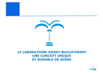
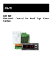
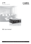
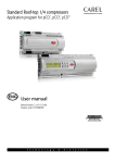
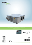
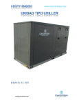
EN Light Electronic Control “LCE” User Manual Control features: Automatic / Manual 3 speed fan 3 point cooling / changeover floating valve 3 point heating floating valve ON-OFF Electric heater Post ventilation Free cooling - Free heating damper Alarm management and diagnostic o Sensor failure o Heater over temperature o Dirty filter alarm Clock program management Remote ON-OFF Remote display with internal sensor Control logic In the following diagrams is explained the summer-winter control logic Treg = regulation probe temperature Tsp = Set point temperature Te = External probe temperature Light control manual-ENG Rev. 00 1 / 10 EN Light Electronic Control “LCE” User Manual Weekly program For each day of the week it is possible to select between 4 programs: Program P1: the unit is turned ON in two different time range (for example one in the morning and one in the afternoon) Program P2: the unit turned ON in a single time range Program P3: the unit is turned ON all the day Program P4: the unit is turned OFF all the day Display Icons: A3-A6: Active weekly program A7-A10: Fan speed A11: ON: Manual OFF BLINKING: Weekly program OFF A12, A13, A15: Working mode / while setting: visualizing set point A16: ON: active alarm BLINKING: resettable alarm A17: Freecooling/Freeheating A19: Clock time viewing A29-A35: Day of the week Light control manual-ENG Rev. 00 2 / 10 EN Light Electronic Control “LCE” User Manual Keyboard Menu Prg List Press together button “Esc” and “Set” Prof: in this section there are the settings for the weekly program o ST1: start time of1st range of 1st program o EN1: end time of 1st range of 1st program o SE1 (summer): set-point of 1st range of 1st program o SE1 (winter): set-point of 1st range of 1st program o ST2: start time of 2nd range of 1st program o EN2: end time of 2nd range of 1st program o SE2 (summer): set-point of 2nd range of 1st program o SE2 (winter): set point of 2nd range of 1st program o ST: start time of 2nd program o END: end time of 2nd program o SET (summer): set-point of 2nd program o SET (winter): set-point of 2nd program Day: in this section there’s the program assignment for each day o Mon: Monday program, possible value P1 P2 P3 P4 o Tue: Tuesday program o Wed: Wednesday program o Thu: Thursday program o Fri: Friday program o Sat: Saturday program o Sun: Sunday program Serv: in this section there is the controller configuration o PWD: insert service password (1) Light control manual-ENG Rev. 00 3 / 10 EN Light Electronic Control “LCE” User Manual o o Pcfg: plant configuration 0= 2 pipes system, unique changeover coil 1= 2 pipes system, cooling coil + electric heater 2= 4 pipes system, cooling coil + heating coil Rprop: regulation probe 0= supply air sensor 1= display sensor Menu Set List Press button “Set” Manual summer set-point Manual winter set-point Alarm folder: o Er01: Regulation sensor failure; effects: The unit is turned off Automatic reset alarm o Er02: External air sensor failure; effects: Free-cooling mode disabled Automatic reset alarm o Er03: Display sensor failure; effects: If Rprop=1 the unit is turned off If Rprop=0 alarm not shown o Er04: Dirty filter alarm; effect None o Er05: Electric heater over-temperature; effects: Electric heater disabled Fan activated Light control manual-ENG Rev. 00 4 / 10 EN Light Electronic Control “LCE” User Manual Wiring diagram For model RKE 03-30 Light control manual-ENG Rev. 00 5 / 10 EN Light Electronic Control “LCE” User Manual For model RKE 40 Light control manual-ENG Rev. 00 6 / 10 EN Light Electronic Control “LCE” User Manual Light control manual-ENG Rev. 00 7 / 10 EN Light Electronic Control “LCE” User Manual Light control manual-ENG Rev. 00 8 / 10 EN Light Electronic Control “LCE” User Manual For model RKE 50-60 Light control manual-ENG Rev. 00 9 / 10 EN Light Electronic Control “LCE” User Manual Light control manual-ENG Rev. 00 10 / 10