1
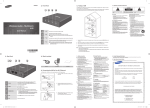
X-10 protocol for the Marmitek XM10 OEM Controller
Marmitek XM10 OEM Controller
*O.E.M Original Equipment Manufacturer
Safety Warnings
x
x
x
x
x
The wiring of your electrical installation is live (230 V) and extremely dangerous. Never connect
the module when plugged into the mains. Always turn off the main switch before starting the
installation.
To prevent short circuits, this product should only be used inside and only in dry spaces. Do not
expose the components to rain or moisture. Do not use the product close to a bath, swimming
pool etc.
Do not expose the components of your systems to extremely high temperatures or bright light
sources.
Do not open the product: the device contains live parts. The product should only be repaired or
serviced by a qualified repairman
In case of improper usage or if you have opened, altered and repaired the product yourself, all
guarantees expire. Marmitek does not accept responsibility in the case of improper usage of the
product or when the product is used for purposes other than specified. Marmitek does not accept
responsibility for additional damage other than covered by the legal product responsibility.
How to implement
Two - way PLC interface for OEM applications (XM10)
The XM10 is a transmitter-receiver that plugs into a regular AC outlet and connects to the controller via a
modular RJ 11 telephone jack. Alternatively, the XM10 may be fitted inside the controller cabinet,
connected to the 230 V AC supply before the power transformer. (This would be a typical installation with
most security panels.)
It provides an opto-coupled 50 Hz. Square wave, synchronised to the zero crossing point of the AC line.
The controller generates X-10 compatible codes synchronised to this zero crossing point. The two-way
interface then couples the X-10 codes onto the AC line.
Two - Way transmission available
The two-way interface transmits and receives X-10 codes. It enables an O.E.M. to develop a system to
control X-10 Modules, and receive X-10 signals from remote sensors (P.I.R. motion detectors for example)
X-10 Code transmission
To transmit X-10 signals the controller must supply 1 ms .envelopes. to the TX input of the interface with
respect to common. These envelopes must be as close as possible to the zero crossing point of the AC
line (see timing diagrams). An opto- coupled output representing the zero crossing point of the power line
is provided for the controller to which X-10 codes are to be synchronised.
X-10 Code reception
The two-way interface uses a custom proprietary I.C. to read X-10 codes from the power line. This takes
a lot of burden off the microprocessor in the controller as it does not have to continuously monitor the
powerline and check all in coming signals (and noise) for validity. Any signals applied to the controller are
error-checked, valid X-10 codes. When a valid X-10 code is received, it is stored in the custom I.C. and
-1-
X-10 protocol for the Marmitek XM10 OEM Controller
applied (in envelope form) to the controller. This output is coincident with the second X-10 transmission.
(X-10 codes are always transmitted in groups of two, except for Bright and Dim.)
Data sent to the controller is valid X-10 data. The start Code (1110) can be used to alert the controller that
an X-10 Code will follow. A .1. bit from the two-way interface appears as a negative going pulse 1.1 ms
long, beginning approximately 100 µs after zero crossing. The controller should sample this data between
500 and 700 µs after zero crossing.
The L.E.D. on the two-way interface gives a visual indication that X-10 codes are being received. The
L.E.D. is illuminated when AC power is applied to the two-way interface and blinks off when X-10 codes
are received. The two-way interface will also receive the codes it transmits, therefore the L.E.D. will also
give an indication of codes being transmitted.
The ability to read X-10 codes from its own output also allows the controller to incorporate data collision
detection. If the code received differs from the code transmitted, the code can be assumed to have been
corrupted by noise ( or another transmission ) on the power line.
The line Monitor capability of the two-way interface allows the controller to ensure that the power line is
free from X-10 signals before starting a transmission. This means that in a multitransmitter system the
controller can minimise contention between transmitters. For example, if after detecting that the line is
free, a transmitter waits for a random number of power line half cycles before transmitting, the chance of
collision is reduced. A different priority can be assigned to each transmitter by including a fixed delay
before the random delay. The shorter the fixed delay, the higher the priority.
Important Safety Notice
Zero volts in this product is directly connected to one side of the AC line.
Therefore, for safety, an ISOLATING power transformer MUST be used when attempting any internal
measurements.
The power supply in the two-way interface are capacitively derived from, and directly referenced to, the
230V AC power line. Care should be taken when monitoring any internal circuitry with an oscilloscope, as
the OV reference in the two-way interface are NOT isolated from 230 volts.
X-10 Protocol
The tables in Figure 1, show the Binary Codes to be transmitted for each House. Code and Key Code.
The Start Code is Always 1110 which is a unique code and is the only code which does not follow the
truecomplement relationship on alternate half cycles.
-2-
X-10 protocol for the Marmitek XM10 OEM Controller
Figure 1
House Code and Key Code Tables
House Code
H8 H4 H2 H1
D8 D4 D2 D1
A 0 1 1 0 1 0 1 1 0
B 1 1 1 0 2 1 1 1 0
C 0 0 1 0 3 0 0 1 0
D 1 0 1 0 4 1 0 1 0
E 0 0 0 1 5 0 0 0 1
F 1 0 0 1 6 1 0 0 1
G 0 1 0 1 7 0 1 0 1
H 1 1 0 1 8 1 1 0 1
I 0 1 1 1 9 0 1 1 1
J 1 1 1 1 10 1 1 1 1
K 0 0 1 1 11 0 0 1 1
L 1 0 1 1 12 1 0 1 1
M 0 0 0 0 13 0 0 0 0
N 1 0 0 0 14 1 0 0 0
O 0 1 0 0 15 0 1 0 0
P 1 1 0 0 16 1 1 0 0
All units off 0 0 0 0
All lights on 0 0 0 1
On 0 0 1 0
Off 0 0 1 1
Dim 0 1 0 0
Bright 0 1 0 1
All Lights Off 0 1 1 0
Extended Code (1) 0 1 1 1
Hail Request 1 0 0 0
Hail Acknowledge 1 0 0 1
Extended Code (3) 1 0 1 0
Program 1 0 1 1
Extended Code (2) 1 1 0 0
Status = on 1 1 0 1
Status = off 1 1 1 0
Status Request 1 1 1 1
Key Codes
D16
0
0
0
0
0
0
0
0
0
0
0
0
0
0
0
0
1
1
1 (shutters open)
1 (shutters close)
1 (shutters up)
1 (shutters down)
1
1 (for data/control)
1
1
1 (for security messages)
1
1 (for meter read & dsm)
1
1
1
Hail Request is transmitted to see if there are any other X-10 transmitters within listening range. This
allows the O.E.M to assign a different House code if a .Hail Acknowledge. is received.
(2) In a Pre-Set Dim instruction, the D8 bit represents the Most Significant Bit of the level and H1, H2, H4
and H8 bits represent the 4 Least Significant Bits.
(3) The Extended Data code is followed by 8 bit bytes which can represent Analog data (after A to D
conversion). There should be no gaps between the Extended Data code and the actual data, and no
gaps between data bytes. The first 8 bit byte can be used to say how many bytes of data will follow. If
gaps are left between data bytes, these codes could be received by X-10 Modules causing erroneous
operation.
Extended Code is similar to Extended Data: 8 Bit bytes which follow Extended Code (with no gaps) can
represent additional codes. This allows the designer to expand beyond the 256 codes presently available.
(1)
-3-
X-10 protocol for the Marmitek XM10 OEM Controller
Extended message format
Start
Code
HC / inv HC
Ext / inv Ext
DC / inv DC
House Code
Extended code
5 bits
01111
2 bits
4 bits
1 1 0 0 H1 H2 H4 H8
Data / inv Data
Command /
inv Command
Command /
inv Command
Unit code
Type/Type.
Func./Func
4 bits
8 bits
D1 D2 D4 D8 D128 ... ...D2 D1
4 bits
4 bits
The command field is split into two nibbles: Type and Function.
Each message is sent twice without a gap.
Example of Extended Data for light sensor:
Light sensor will respond to messages with the previous serial format and the response will be in the same
format.
Request for light data for the module addressed in the House Code and Unit Code fields:
Start
Code
HC / inv HC
Ext / inv Ext
DC / inv DC
House Code
Extended code
5 bits
01111
2 bits
4 bits
1 1 0 0 H1 H2 H4 H8
Data / inv Data
Command /
inv Command
Command /
inv Command
Unit code
Type/Type.
Func./Func
4 bits
8 bits
D1 D2 D4 D8 D128 ... ...D2 D1
4 bits
0001
4 bits
0001
The corresponding response will be Ambient Light Data from the module addressed in the House Code
and Unit Code fields:
Start
Code
HC / inv HC
Ext / inv Ext
DC / inv DC
House Code
Extended code
5 bits
01111
2 bits
4 bits
1 1 0 0 H1 H2 H4 H8
Data / inv Data
Command /
inv Command
Command /
inv Command
Unit code
Type/Type.
Func./Func
4 bits
8 bits
D1 D2 D4 D8 D128 ... ...D2 D1
4 bits
0001
4 bits
1111
The ambient light data is encoded in the data field in the following manner:
D128 D64
D32 D16
D8 D4
D2 D1
Command /
Command /
inv Command inv Command
0
0
1
1
Light Level
Light Level
Light Level
Light Level
Range 0-630
Range 0-6 300
Range 0-63 000
Range 0-630 000
steps of 10
steps of 100
steps of 1 000
steps of 10 000
(0-315
(0-3 150
(0-31 500
(0-315 000
0
1
0
1
-4-
Lux steps of 5)
Lux steps of 50)
Lux steps of 500)
Lux steps of 5 000)
X-10 protocol for the Marmitek XM10 OEM Controller
Important notes
NOTE 1:
X-10 Receiver Modules require a .silence. of a least 3 power line cycles between each pair of 11 bit code
transmissions (no gaps between each pair). The one exception to this rule is bright and dim codes.
These are transmitted continuously with no gaps between each 11 bit dim code or 11 bit bright code. A 3
cycle gap is necessary between different codes. i.e. between bright and dim, or on and dim, or on and
bright etc..
NOTE 2:
The .two-way. Power Line Interface can receive Extended Code or Extended Data.
NOTE 3:
The two-way interface can receive dim and bright codes but the output will represent the first dim or bright
codes like the codes which were transmitted.
Transmission Timing Diagrams
A square wave representing zero crossing detect is provided by the two-way interface and is within 100 µs
of the zero crossing point of the AC power line. The output signal envelope from the controller, should be
within 50 µ of the zero crossing detect. The signal envelope should be 1 ms (-50 µs + 100 µs). See Figure
2.
Figure 2: Transmit Timing Diagrams
-5-
X-10 protocol for the Marmitek XM10 OEM Controller
Opto-Coupled 50 Hz reference output
Transmissions are to be synchronised to the zero crossing point of the AC power line and should be as
close to true zero crossing as possible. The two-way interface are designed to be interfaced to other
microprocessor circuitry which outputs X-10 codes synchronised to the zero crossing point of the AC
power line. It is therefore necessary to provide a zero crossing reference for the controller microprocessor.
It is likely that this microprocessor will have its own .isolated. power supply. It is necessary to maintain
this isolation, therefore the trigger circuit normally used in X-10 controllers is not desirable as this would
reference the controller power supply to the AC power line. It is also not desirable to take the trigger from
the secondary side of the power supply transformer as some phase shift is likely to occur. It is therefore
necessary to provide an opto-coupled 50 Hz reference.
An opto-coupled 50 Hz square wave is provided at the output of the two-way interface. X-10 codes
generated by the controller are to be synchronised to this zero crossing reference. The X-10 code
envelope generate by the controller is applied to the two-way interface which modulates the envelope with
120 kHz, and capacitively couples it to the AC power line.
Opto-Couple Signal Imput
The input signal required from the O.E.M product is the signal .envelope. of the X-10 code format, i.e.
High for 1 ms. coincident with zero crossing represents a binary .1. and gates the 120 kHz, oscillator
through to the output drive circuit thus transmitting 120 kHz, onto the AC power line for 1ms.
Low for 1 ms. coincident with the zero crossing point represents a binary .0. and turns the 120 kHz
oscillator/output circuit off for the duration of the 1 ms input.
Opto-Coupled Signal Output
The .X-10 received. output from the two-way interface coincides with the second half of each X-10
transmission.
This output is the envelope of the bursts of 120 kHz received. Only the envelope corresponding
to the first burst of each group of 3 bursts is available at the output of the
two-way interface. See Figures 3, 4 and 5.
Start
Code
House
Code
Function
Code
Start
Code
House
Code
Function
Code
Start
Code
House
Code
Function
Code
Figure 3: X-10 code received from the AC power line
-6-
X-10 protocol for the Marmitek XM10 OEM Controller
Received Timing Diagrams
Figure 4
figure 5
-7-
X-10 protocol for the Marmitek XM10 OEM Controller
Typical Controller Connection Diagram
Connection between the controller is via a standard modular phone jack, the connections for which are as
follows:
1. B Zero crossing detect output (with respect to 2).
2. R Common.
3. G X-10 received envelope output (with respect to 2).
4. Y X-10 transmit envelope input (with respect to 2).
-8-
X-10 protocol for the Marmitek XM10 OEM Controller
Technical data
Supply voltage:
Ambient temperature:
DC characteristics:
Serial data input:
Min. logic «1»:
Max. logic «1»:
Max. logic «0»:
230V +10% -15% 50 Hz
- 10° C to + 40° C (operation)
- 20° C to + 70° C (storage)
4 V input will sink approx 2,5 mA
20 V input will sink approx 18 mA
0.8 V will sink approx 0,1 mA
(Voltages and currents with respect to terminal 2)
Note: this output is an open collector transistor. Therefore, the
logic «1» voltage is quoted as a reference for defining the
output leakage current. An output pullup resistor is required
to generate a logic level. The pullup can be returned to any
voltage up to 20 V with respect to terminal 2.
AC characteristics:
HF output to AC power line:
60 mW average into 5W
Conforms to Class 116 of EN50065-1:
Carrier frequency:
load (2,5 V pk-pk instant.)
120 kHz ± 2 kHz
Max. phase delay betwen 0 crossing
point of AC power line and 0 crossing
detect output (either transition):
Max. allowable delay between
transitions on 0 crossing detect output
and serial data input «0» - «1»
transition:
100 msec
50 msec
Max. delay betwen serial input envelope
«0» - «1» transition and carrier burst
reaching 90 %:
50 msec
Width of X10 enveloppe :
1 ms +100 msec -50msec
Isolation voltage :
4 kV rms 50Hz for 1 min.
-9-
X-10 protocol for the Marmitek XM10 OEM Controller
Environmental Information for Customers in the European Union
European Directive 2002/96/EC requires that the equipment bearing this symbol on the product
and/or its packaging must not be disposed of with unsorted municipal waste. The symbol indicates
that this product should be disposed of separately from regular household waste streams. It
is your responsibility to dispose of this and other electric and electronic equipment via designated
collection facilities appointed by the government or local authorities. Correct disposal and recycling
will help prevent potential negative consequences to the environment and human health.
For more detailed information about the disposal of your old equipment, please contact your local
authorities, waste disposal service, or the shop where you purchased the product.
DECLARATION OF CONFORMITY
Hereby, Marmitek BV, declares that this XM10 is in compliance with the essential
requirements and other relevant provisions of the following Directives:
Council Directive 89/336/EEC of 3 May 1989 on the approximation of the laws of the Member States relating to
electromagnetic compatibility
Council Directive 73/23/EEC of 19 February 1973 on the harmonization of the laws of Member States relating
to electrical equipment designed for use within certain voltage limits
Hiermit erklärt Marmitek BV die Übereinstimmung des Gerätes XM10 den grundlegenden
Anforderungen und den anderen relevanten Festlegungen der Richtliniën:
Richtlinie 89/336/EWG des Rates vom 3. Mai 1989 zur Angleichung der Rechtsvorschriften der Mitgliedstaaten
über die elektromagnetische Verträglichkeit
Richtlinie 73/23/EWG des Rates vom 19. Februar 1973 zur Angleichung der Rechtsvorschriften
der Mitgliedstaaten betreffend elektrische Betriebsmittel zur Verwendung innerhalb bestimmter
Spannungsgrenzen
Par la présente Marmitek BV déclare que l'appareil XM10 est conforme aux exigences
essentielles et aux autres dispositions pertinentes de la directives:
Directive 89/336/CEE du Conseil du 3 mai 1989 concernant le rapprochement des législations des États
membres relatives à la compatibilité électromagnétique
Directive 73/23/CEE du Conseil, du 19 février 1973, concernant le rapprochement des
législations des États membres relatives au matériel électrique destiné à être employé dans
certaines limites de tension
Marmitek BV declara que este XM10 cumple con las exigencias
esenciales y con las demás reglas relevantes de la directriz:
Directiva 89/336/CEE del Consejo de 3 de mayo de 1989 sobre la aproximación de las legislaciones de los
Estados Miembros relativas a la compatibilidad electromagnética
Directiva 73/23/CEE del Consejo, de 19 de febrero de 1973, relativa a la aproximación de las legislaciones de
los Estados Miembros sobre el material eléctrico destinado a utilizarse con determinados límites de tensión
- 10 -
X-10 protocol for the Marmitek XM10 OEM Controller
Con ciò, Marmitek BV, dichiara che il XM10 è conforme ai requisiti essenziali ed altre
disposizioni relative alla Direttiva :
Direttiva 89/336/CEE del Consiglio del 3 maggio 1989 per il ravvicinamento delle legislazioni degli Stati
Membri relative alla compatibilità elettromagnetica
Direttiva 73/23/CEE del Consiglio, del 19 febbraio 1973, concernente il ravvicinamento delle legislazioni degli
Stati Membri relative al materiale elettrico destinato ad essere adoperato entro taluni limiti di tensione
Bij deze verklaart Marmitek BV, dat deze XM10 voldoet aan de essentiële eisen en aan de
overige relevante bepalingen van Richtlijnen:
Richtlijn 89/336/EEG van de Raad van 3 mei 1989 betreffende de onderlinge aanpassing van de wetgevingen
van de Lid-Staten inzake elektromagnetische compatibiliteit
Richtlijn 73/23/EEG van de Raad van 19 februari 1973 betreffende de onderlinge aanpassing van de wettelijke
voorschriften der Lid-Staten inzake elektrisch materiaal bestemd voor gebruik binnen bepaalde
spanningsgrenzen
MARMITEK BV - P.O. BOX 4257 - 5604 EG EINDHOVEN – NETHERLANDS
Copyrights
Marmitek is a trademark of Pattitude B.V. XM10™ is a trademark of Marmitek B.V. All rights reserved.
Copyright and all other proprietary rights in the content (including but not limited to model numbers, software, audio,
video, text and photographs) rests with Marmitek B.V. Any use of the Content, but without limitation, distribution,
reproduction, modification, display or transmission without the prior written consent of Marmitek is strictly prohibited.
All copyright and other proprietary notices shall be retained on all reproductions.
20118-20101025
- 11 -