1
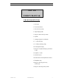
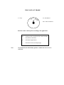
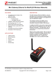
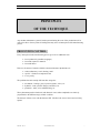
SDT 150 - USER’S MANUAL
PRINCIPLES
OF THE TECHNIQUE
Any modern maintenance system is based upon monitoring the wear of the production tools in
order to be able to foresee points of breakage that may cause an interruption of the manufacturing
process
PREVENTIVE CONTROL
Every interruption in the manufacturing process gives rise to additional costs :
• lower productivity (machine stoppages)
• increased expenses in material
• increased labour
However, the means of control available to most maintenance departments are :
• either rudimentary : touch, hearing, smell
• specific : vibration or temperature tests
• or very costly.
The problems that arise mainly falls into three categories :
• mechanical : bearings, gears, injection systems, valves, etc.
• hydraulic : leaks, pressure changes, autolifters, etc.
• pneumatic : leaks, valve malfunctioning, etc.
These phenomena produce both sonic and ultrasonic waves whose amplitudes are relatively
proportional to the different stages of their evolution.
The analysis of these waves with the detector SDT 150 allows the user to foresee and avoid any
rupture.
ME 150E - Rév. 0
28/01/2004/SDT150E
1
SDT 150 - USER’S MANUAL
SOUND AND ULTRASOUNDS
Sound is generally produced by a vibrating body. The surrounding air takes part in the process,
forms waves around the vibrating object and transmits sounds.
The frequency is measured in cycles per second or hertz, which indicates the number of vibrations
the sound wave makes in a certain time span.
The smaller the number of vibrations, the lower the frequency.
Vibrations of ultrasound are similar to those of normal sound but ultrasound is above 20 kHz and is
inaudible to the human ear, limited between 15 and 20 kHz.
Unlike the dispersed emission of sound, ultrasound is propagated in a directional way and may be
compared to a light beam whose intensity diminishes with the distance. In fact, how higher the
frequency, how more sound is absorbed by the surrounding air. It is the high degree of absorption
of the high frequency emission that gives the ultrasound its directionality.
Ultrasound is naturally generated by :
• high or low pressure which causes pneumatic or hydraulic problems ;
• friction which causes mechanical problems ;
• discharges which cause electrical problems.
Ultrasonic sound is also artificially generated by means of a transmitter while testing tightness.
ME 150E - Rév. 0
28/01/2004/SDT150E
2
SDT 150 - USER’S MANUAL
TESTING PRINCIPLES
• To listen is to understand
An ultrasonic detector can pick up ultrasonic frequencies between 36.7 and 40.7 kHz and convert
them into frequencies audible to the user in order to allow him to gain access to a part of the
environment, previously imperceptible to him.
For some applications, when using the contact probe , the SDT 150 is able to detect audible
vibrations between 30 Hz and 2 kHz.
• To measure is to master
The ultrasonic detector measures and indicates in dB (decibels) the maximum value of the signal
picked up.
• To simplify is to gain access for all
A Led analogue display helps the user to calibrate the receiver on the basis of the ultrasonic source
being studied
To analyse is to understand
An ultrasonic detector includes an audio outlet enabling the user by means of an oscilloscope to
visualise the signals picked up by the detector.
• Optimum processing through computers
The SDT 1000 data collector enables the user to identify, date and memorise 999 measurements.
The module is equipped with a RS232 link and is capable of handling date with the assistance of a
personal computer.
THE ULTRASONIC SOURCE
Regarding the diversity of ultrasonic sources in industry, an ultrasonic source must be tested
without interference.
Without an adequate measuring instrument, it is impossible to determine the frequency of
ultrasonic interference. A factory that sounds very noisy to the human ear may actually be quiet
from the ultrasonic viewpoint and vice versa.
Therefore an ultrasonic detector may be equipped with accessories able to isolate one from several
sources.
ME 150E - Rév. 0
28/01/2004/SDT150E
3
SDT 150 - USER’S MANUAL
THE DETECTOR’S FREQUENCY COVERAGE
The detector’s frequency coverage has carefully been selected to ensure preservation of the
message contained in the signal during transformation into an audible frequency.
This feature enables the user to acoustically differentiate various ultrasonic sources.
Therefore the noise of a leak emitted by the detector is the same as the untreated noise of a normal
leak. The same is true for the sound of friction caused by two metal surfaces.
ANGLE OF RECEPTION
Thanks to the directional nature of the ultrasonic emission, two sources located one next to the
other or two crossed sources may be isolated by reducing the angle of reception.
DETECTION BY CONTACT
The contact probe is used to test sound vibrations or ultrasound vibrations inside a metal casing
(housing, bearings, valve bodies, etc.).
As the test is carried out through direct contact, there is no danger of interference.
The detector equipped with this type of sensor, is able to test a bearing within a complex
mechanical assembly, a gear within a reduction gear or a valve.
ACTIVE CONTROL
Ultrasonic waves produced by a transmitter placed within an enclosed body are released through
the tiniest opening.
Any leak may consequently easily be detected by means of a receiver.
ME 150E - Rév. 0
28/01/2004/SDT150E
4
SDT 150 - USER’S MANUAL
SDT 150
USER’S MANUAL
THE SDT 150 DETECTOR
1. PVC-tube
2. Precision indicator
3. Piezo-electric pick up
4. Digital display (dB)
5. Plug for contact and clip sensors
6. Speaker
7. Analogue display for calibration
8. T = ON-OFF lamp
9. B = Battery discharge lamp
10. Led amplitude display
11. Selector for amplitude display (maximum
in dB)
12. Amplifier - 20 dB
13. ON-OFF switch
14. Potentiometer with amplification selector
15. Headphone plug
16. Plug for connecting SDT 100,
oscilloscope, ...
17. Plug for connecting battery loader
ME 150E - Rév. 0
28/01/2004/SDT150E
5
THE CONTACT PROBE
M
F = Flow
F
M = Mechanical
SM
SM = Slow mechanical
Selection on the contact probe according to the application
Note :
SM
y Bearings with a speed factor lower than 300 RPM
y Detection of water flow
M
y Mechanical applications
F
y Detection of leaks or fluid passages
On position SM, the SDT 150 may produce a whistle tone in case of oversaturation.
SDT 150 - USER’S MANUAL
Switching ON
After loading the battery block, turn on the ON-OFF switch (13).
The ON-OFF indicator lamp (T) - the first Led green light - will light up.
The lamp (B) indicating the battery level (9) - the last Led red lamp - will flash faster and faster as
the batteries lose their charge and will burn steadily when the batteries are dead.
The batteries should be recharged at least once a month. The equipment should not be used if the
batteries are dead.
Adjusting the amplifier
The two analogue indicators (7) help the user to calibrate the device. They give information on the
status of the amplifier’s saturation, thus facilitating adjustment.
The potentiometer (14) is switched to the lighted Led (7). The accuracy of a measurement is
guaranteed within 1 dB, provided the two Led’s are off during measurement.
If a signal is discontinuous, the right Led should flash. The potentiometer should be adjusted so that
the left Led does not light up under any circumstance during reception of a signal.
In case of saturation, the amplifier/attenuator (12) enables the user to increase/decrease the level of
amplification by 20 dB.
Digital display
The digital display (4) indicates in dB the maximum strength of the ultrasonic signal being
measured. The range of measurement is 9 to 99 dB (Ref. 0 dB = 1µV).
In the M- position (11), the display is disconnected to reduce battery wear.
Constant or repetitive pressure on the M+ switch (11) will display the level of the signal being
measured. After 7 seconds, the display goes off unless pressure is maintained on the switch.
The device’s function is to measure maximum signal strength. The values displayed may therefore
vary if the signal increases in strength. In order to display the level of a diminishing signal, release
and then press the M+ switch.
ME 150E - Rév. 0
28/01/2004/SDT150E
7
SDT 150 - USER’S MANUAL
Accessories
The detector transforms ultrasonic waves into audible sound which is heard over the built-in
speaker (6) which is automatically switched off when the headphones are plugged in (15).
The precision indicator (2) is screwed into the case at the location of the sensor (3).
Audio output
1. Audio output
This output (16) produces alternating current whose frequency is equal to the difference
between the input frequency and that of the oscillator (from 0 to 2 kHz) and whose amplitude is
100 mW RMS when the second red diode is on.
2. Direct current output :
The direct current varies on the basis of the level measured and ranges from 0,1 V and V.
The connection will give a direct reading of the dB level.
For example : 700 mV/ 70 dB ; 500 mV / 50 dB ; 0 mV / 0 dB
ME 150E - Rév. 0
28/01/2004/SDT150E
8
SDT 150 - USER’S MANUAL
COMPLETE SETS SDT 150
The SDT 150 is available in 2 versions :
y SDT 150 Standard
y SDT 150 Meca
SDT 150 Standard
1 x Receiver SDT 150
1 x Spare battery
1 x Battery loader
1 x Precision indicator
1 x Contact probe
1 x Headphone 130 dB
1 x Delsey case
1 x User’s manual
SDT 150 Meca
1 x Receiver SDT 150
1 x SDT 1000 Datacollector
1 x Spare battery
1 x Battery loader
1 x Precision indicator
1 x Contact probe
1 x Magnetic sensor
1 x Headphone 130 dB
1 x Delsey case
1 x User’s manual
Accessories
These sets can be completed with several optional accessories :
a) Contact probe
b) Contact tong (55 mm in open position)
c) Magnetic sensor
d) M6 screwable sensor
e) Waterproof sensor diameter 8 mm
f) Waterproof sensor diameter 25 mm
g) Open sensor 16 mm
h) Leathern carrying case
i) Extra batteries
j) Transmitter 25 mW bi-sonic
k) Transmitter 25 mW directional
l) Transmitter 200 mW bi-sonic
m) Transmitter 200 mW directional
n) Connection cable for oscilloscope and SDT 1000
ME 150E - Rév. 0
28/01/2004/SDT150E
9
SDT 150 - USER’S MANUAL
RECEIVER : TECHNICAL DATA
- 5 dB/µV → !!! /mV dans les spec de la doc §§??
•
Average signal/Noise ratio
•
Conversion error : ± 1 dB
•
Oscillator frequency : 38.4 kHz
•
Low-pass Butterwurth filter of 4th order : 2 kHz
•
Band width (-3 dB) : 200 - 2 kHz
36.70 - 38.35 : 1.65 kHz
38.45 - 40.70 : 2.25 kHz
•
Total band width of the receiver : 3.85 kHz
•
Impedance input: 3,5 kOhm
•
Maximum input voltage per remote sensor : 100 mV
•
Rate of charge : 8 to 10 hours → ??
•
Autonomy : 5 hours without display ; 3,5 hours with display
•
Battery capacity : 400 mAh (NiCd)
•
Dimensions : (L x W x H) → 260 x 79 x 60 (mm)
•
Weight : → 980 g
•
Connections :
ME 150E - Rév. 0
Charger → Friwo 2-pole → ??
Headphones → Stereo jack 6.3 mm → ??
Contact probe → Bantam tiny 4.4 mm → ??
28/01/2004/SDT150E
10
SDT 150 - USER’S MANUAL
TRANSMITTERS
The transmitter models differ in power and emission tonality. They are powered by a rechargeable
NiCd battery built in the device and requires recharging after about 6 hours.
The transmitter is equipped with :
1 piezo-electric sensor
1 red led battery discharge indicator lamp
1 green led ON-OFF indicator lamp
1 ON-OFF switch
1 High-low switch for setting emission strength
1 Charger input
1 Input for independent sensor
Technical specifications of transmitters
Directional
25 mW
UB
Ca
f
Pm
O
IL
IH
Bi-sonic
200 mW
9,6 V
100 mA/h
39,50 kHz
25 mW
150°
8 mA
12 mA
9,6 V
100 mA/h
39,50 kHz
200 mW
150°
9 mA
24 mA
Dimensions :
Length
Width
Height
Weight
230 g
ME 150E - Rév. 0
25 mW
200 mW
9,6 V
100 mA/h
39,50 kHz ± 100 Hz
25 mW
150°
8 mA
12 mA
9,6 V
100 mA/h
39,50 kHz ± 100 Hz
200 mW
150°
9 mA
24 mA
107,5 mm
35 mm
40 mm
28/01/2004/SDT150E
11
SDT 150 - USER’S MANUAL
BATTERIES
The block containing 8 NiCd batteries is rechargeable only using the recharger supplied with the
device.
The battery block may be recharged via the plug installed on the receiver (17) or the plug located
on the battery block.
The screwdriver furnished with the device may be used to unscrew the panel on the back of the
receiver. The battery may be loaded without regard to polarity.
ME 150E - Rév. 0
28/01/2004/SDT150E
12
SDT 150 - USER’S MANUAL
APPLYING
THE TECHNIQUE
Detecting and pinpointing leaks
Material used :
SDT 150 detector
Precision indicator
(Liquid revealer)
(Transmitter)
(Contact probe)
1.
Sweep the space around the circuit (valves, conduits, etc.) with the detector to pinpoint the
ultrasonic beam produced by the leak and close in on the source of the beam.
2.
In case of multiple leaks or bothersome interference, use the precision indicator.
3.
If the pressure of the leak is less than 0.2 bar, spray the suspect areas with the liquid revealer
to help detect the leaks.
4.
The smallest detectable leak is 4 cc/min which is reduced to 1 cc/min by using the liquid
revealer under a minimum pressure of 1 bar.
5.
In the event of a leak under vacuum, the ultrasonic beam of the leak will originate in the
body under vacuum. For this reason, such a leak must be rather large before it can be
detected. Detection is similar to these in the case of pressure leaks.
A leak may be detected by placing the transmitter inside the body under vacuum.
This may be carried out either without creating a vacuum or by creating a medium vacuum.
In the first case, the ultrasonic wave indicates the weak points of the joint that are usually the
cause of the current or future leaks.
If a medium vacuum is created in the body being tested in such a way that the joint adheres
to the wall, ultrasonic waves detected will indicate the origin of the leak.
ME 150E - Rév. 0
28/01/2004/SDT150E
13
SDT 150 - USER’S MANUAL
Testing bearings
Material used :
SDT 150 detector
Contact probe (position M or SM)
Precision indicator
Magnetic sensor
BALL BEARINGS
The friction of the balls against each other and of the balls against the channel of a bearing
produces an acoustic emission.
When the bearing is new, it is well lubricated and the film of grease absorbs the emission generated
by the balls. When the thickness of the film decreases, the amplitude of the emission increases
according to the deterioration of the bearing.
By studying amplitudes in relation to time, it is possible to produce a graph showing the life of the
bearing and thus anticipate its failure.
However, for each bearing this curve must be produced taking account of the following points :
• its actual characteristics (RPM, load, ...)
• its environment (heat, dust, humidity), its influence is of utmost importance in the life of
the bearing.
Two identical bearings which have been placed in two different places will last for different
lengths of time.
The detector SDT 150 enables to :
• make a check up in time through successive measurements, possibly depicted on a
graph by means of the SDT 1000 ;
• make an instant check up which gives a diagnosis of the state of the bearing whatever
its environment. In case of doubt, comparing with bearings of the same type is
recommended.
Position of the contact probe
CONDITION
Good
Insufficient lubrication
Seized bearing
SM
Bearings
< 300 RPM
It is impossible to provide an
exact chart for
slow bearings, too many
variations
depend on their environment.
M
Bearings
> 300 RPM
0 → 50/60 dB
50/60 → 70 dB
> 70 dB
N.B. The position F of the contact probe is used for checking the passage of fluids, tightness
control of valves, taps, jacks, pneumatic detection,...
ME 150E - Rév. 0
28/01/2004/SDT150E
14
SDT 150 - USER’S MANUAL
The references given in dB are relative and variations may occur :
• whether the bearing’s usual conditions of use are modified. Modifications of the speed
causes a modification in the amplitude of the signal without however exceeding the
tolerances in dB corresponding to the condition of the bearing.
• according to the thickness of the housing surrounding the bearing or when the bearing is
incorporated in the frame of a machine (as in some rotary presses).
Control IN RESPECT OF TIME makes it possible top produce a curve showing the actual life of a
bearing studied and effectively plan not only the replacement of that bearing but also its lubrication
cycle.
This type of control makes it possible to dispense with systematic maintenance (lubrication every X
hours, replacement every Y hours) and increase productivity (less hours when the machine is
stopped), decrease maintenance costs (savings on greasing, bearings) and in certain case, improve
the quality of production.
DETECTION PROCEDURE
1. First of all, using the detector, scan the mechanical environment of which the bearing
forms a part in order to identify any abnormal acoustic source from another mechanical
part of the assembly (reducer, coupling,...)
2. Then place the contact probe on the bearing casing, select the correct position according
to the bearing’s speed.
SM
M
Speed less than 300 RPM
Mechanical applications
3. For very slow bearings, between 2,5 and 300 RPM, use the magnetic sensor.
4. Calibrate the detector by using the potentiometer to select the minimum amplification,
with the led’s unlit.
In the case of saturation, the detector may produce a whistle when the contact probe is
on position SM.
5. Taking the measurements
For repeated controls, it is important to mark the position where the contact probe
is placed so that it is always placed on the same spot.
For very slow bearings (50 RPM), it is necessary to use the magnetic sensor.
ME 150E - Rév. 0
28/01/2004/SDT150E
15
SDT 150 - USER’S MANUAL
CYLINDER AND ROLLER BEARINGS
The amplitude in dB for these types of bearings, even when they are in good condition, is always
greater than that produced by ball bearings because they produce more friction.
Wear, however, appears much more slowly. The dB threshold remains stable over time and is
accentuated only if a problem arises.
Alignment of couplings
Experience has shown that a detector is useful in testing the alignment of a coupling. A well
aligned coupling makes a whistling sound while a poorly aligned coupling produces a regular,
staccato sound.
DETECTION INSTRUCTIONS
1. Place the precision indicator on the detector.
2. Position the indicator along the axis of the coupling or on the crankcase’s coupling in
such a way as to pick up only the sound of the coupling. Do not position the indicator
facing the motor.
3. If the signal is louder than 55 dB, the vibrations produced by the imbalance will cause
rapid wear in the bearing.
This type of test is particularly useful in the installation of pumps and similar devices and to check
a machine following repair work.
ME 150E - Rév. 0
28/01/2004/SDT150E
16
SDT 150 - USER’S MANUAL
Gear trains
Material used :
SDT 150 detector
Contact probe (position M)
Precision indicator
As the teeth of gear wheels mesh, they produce friction and ultrasonic sound which enables the user
to :
• evaluate gear wear by means of control over time ;
• diagnose the defective wheel either through an irregular ultrasonic sound or a dB
reading that is higher than that for other wheels.
DETECTION INSTRUCTIONS
1. Listen to the noise produced on both sides of the housing. A gear train in good
condition produces constant and regular ultrasonic emissions. Discontinuous ultrasonic
sound is the sign of a worn gear wheel.
2. Take a reading at each gear wheel, first with the precision indicator, then with the
contact probe on position M.
Given the wide range of materials used in making gears, it is impossible to give precise reference
values. The user should therefore compare readings with other similar gears or periodically
measure the gear noise over time to check wear.
ME 150E - Rév. 0
28/01/2004/SDT150E
17
SDT 150 - USER’S MANUAL
Valves
Material used :
SDT 150 detector
Contact probe (position F or SM for water flow)
Magnetic sensor
When a valve or a capacitor is open, the contact probe enables the user to hear the flow of gas or
fluid. A closed and tight valve does not produce any ultrasonic sound. Any sound therefore
indicates a leak.
DETECTION INSTRUCTIONS
1. Place the probe on position F for fluid or SM for water flow.
2. Listen by means of the contact probe to the movements of the flaps and the flow of gas
or fluid in the valve or capacitor.
A continuous signal indicates :
• the valve is open (normal)
• the valve is stuck in the open position (defective valve).
The absence of a signal indicates :
• the valve is in a closed position (normal)
• the valve is stuck in the closed position (defective
REMARKS :
According to the thickness of some large manual valves, it might be difficult to detect a sufficiently
strong signal with the contact probe. In this case, it is advised to use the magnetic sensor.
Confusion may rise between ultrasonic waves produced by a leak and those produced by the back
flow of the liquid under high pressure against the closed valve or capacitor. However a leak will
always produce a higher signal than back flow, which may be measured at times of normal
functioning for purposes of comparison.
ME 150E - Rév. 0
28/01/2004/SDT150E
18
SDT 150 - USER’S MANUAL
Pinpointing unusual noises or vibrations
Material used :
SDT 150 detector
Precision indicator
Contact probe (position F or M or SM)
There is no set procedure. Detection must be carried out on a case-by -case basis.
DETECTION INSTRUCTIONS
1. Turn the device on and listen.
2. Use the contact probe to pinpoint unusual noises or vibrations, for example in the
housing of a poorly installed bearing. Use the precision indicator to pinpoint an unusual
noise inside a machine.
Corona discharge
Material used :
SDT 150 detector
Precision indicator
Small electrical discharges (corona), the appearance of sparks and their passage from one body to
another produce disturbances in the air and ultrasonic “noises”.
Corona discharges may occur in high voltage wires through arcing of electric cables, in
transformers, insulators, motors, contact brushes, etc.
ME 150E - Rév. 0
28/01/2004/SDT150E
19
SDT 150 - USER’S MANUAL
Hydraulic circuits
Material used :
SDT 150 detector
Contact probe
Mobile sensor
Magnetic sensor
DETECTION INSTRUCTIONS
1. Put the contact probe on position F for fluid.
2. Measure the dB of the signal while the circuit is closed. The dB level indicates the
turbulence created by backwash against the closed valve.
3. Measure the dB of the signal produced while the valve is open.
4. The difference between the two signals enables the user to detect a leak.
5. If the circuit is obstructed, the ultrasonic signal fall significantly.
6. In devices such as shock absorbers, cartridges and bulldozers, a leak can be detected by
the formation of air bubbles that burst when under pressure. The signal produced by the
bubbles is easily detected by the sensor.
7. If the passage of the fluid is not audible, put the contact probe on position SM.
.
Controlling tightness using the transmitter
Material used :
SDT 150 Detector
Precision indicator
Transmitter
Mobile sensor (for reasons of accessibility)
Liquid revealer
1.
Place the transmitter inside the body to be tested and first use the detector on its own and
afterwards the detector equipped with the precision indicator to pinpoint any leak.
2.
If the size of the body being tested is large enough, carry out the same test in reverse i.e. with
the transmitter outside the body in order to check whether the point of entry of an infiltration
is also the point of exit.
3.
The type of signal and the transmitter’s power will depend on the type of body being tested.
1. Power
A. If the body being tested is large or has thick components, use 200 mW.
B. For small bodies with plastic walls or thin metal, 25 mW is advisable.
ME 150E - Rév. 0
28/01/2004/SDT150E
20
SDT 150 - USER’S MANUAL
2. Signal
a) The directional transmitter produces an ultrasonic beam similar to that of a spotlight.
It is used to detect individual leaks, even if they are located only a few millimetres
apart.
b) The bi-sonic transmitter has a broader scope of action and is comparable to neon light. It
is generally used in industry as a preliminary test to determine whether a body is tight. It
may also be used to pinpoint defects with a high degree of accuracy.
c) Both transmitters are perfectly complementary and enable the user to detect accurately
any leak. In large volumes, the bi-sonic detects a problem and the directional transmitter
pinpoints it.
d) The propagation of the transmitters depends on the body’s housing which may or may
not facilitate the reflection of ultrasonic signals such as in a car.
In any event, a preliminary test should be conducted.
When large bodies are being tested such as busses , aeroplanes, boats, roofs, etc. the SDT 13
multitransmitter should be used in order to ensure a sufficiently strong and even transmission
signal.
Some bodies, according to their shape, thickness of their walls etc. cannot be tested by ultrasonic
signals only because they remain confined within the body.
An alternative solution must be found :
1.
AIR + ULTRASONIC SIGNALS
Place the body under pressure and pinpoint leaks using the detector.
2.
AIR + LIQUID REVEALER + ULTRASONIC SIGNALS
a) when the pressure used is less than 1 bar
b) when micro-leaks are suspected (less than 4 cc/minute)
3.
AIR + WATER + ULTRASONIC SIGNALS
The volume under pressure is immersed in water. Any leakage causes bubbles to escape
which produce a large number of ultrasounds when they burst on the surface, even if the
bubbles are scarcely visible. This process can be used to control the leak tightness of a
volume, although it does not allow to accurately detect the origin of the leakage.
4.
LOW PRESSURE + ULTRASOUND
If the volume is suitable, it may be placed under low pressure (600 mBar) after having
previously placed an ultrasonic sensor inside. The penetration of air through a leak may be
detected all the more easily as the volume forms a resonance chamber.
ME 150E - Rév. 0
28/01/2004/SDT150E
21
SDT 150 - USER’S MANUAL
5.
LOW PRESSURE + LIQUID + SOUND SIGNAL
If the volume is filled with liquid before it is placed under low pressure, any leakage causes
bubbles of air which can be detected using a mobile sensor placed in the liquid.
Points 4 and 5 may be combined when the liquid does not completely fill the volume.
ME 150E - Rév. 0
28/01/2004/SDT150E
22
SDT 150 - USER’S MANUAL
WARRANTY
Above and beyond our general conditions of sales, the receiver SDT 150 is guaranteed for 1
year from the date of delivery.
The warranty covers the entire device, except batteries and includes the replacement free of charge
of any part deemed defective, either because of faulty material or factory assembly.
The warranty does not apply if the device is incorrectly used or mistreated, if it is not maintained
properly or if the wrong voltage is used.
The warranty does not apply to devices that have been checked, transformed, repaired or
disassembled, partially or completely, by a person not authorised by our department, nor the
devices to which improper parts or components have been added.
Customer is responsible of following :
a) shipping costs to and from the factory ;
b) packaging costs.
The warranty for the headphones, the charger and the batteries is limited to three months.
ME 150E - Rév. 0
28/01/2004/SDT150E
23
SDT 150 - USER’S MANUAL
IMPORTANT RECOMMENDATIONS
1.
Do not use the SDT 150 in a dusty area as the device’s sensor may become dirty.
If necessary, use the various tight accessories : the waterproof sensor, the magnetic or the
screwable sensor.
2.
Prevent water, grease, dust or similar substances from penetrating the sensors (use the
waterproof sensors).
3.
The life of the batteries depends on their correct usage and the maintenance of a minimum
charge.
Therefore :
• replace the battery block as soon as the led indicates minimum battery level ;
• recharge the battery block immediately and only by means of the charger
supplied with the device ;
• recharge the unused battery blocks every two weeks.
4.
Normal operating temperature : -10°C / + 50°C
Note : the equipment may be used for occasional working at low temperature, up to -25°C,
for a continuous period of time of maximum 15 hours.
5.
When using the contact probe or magnetic sensor to take contact readings, clean any nonconducting surface such as paint, grease, etc. and mark the exact point where the check up is
done in order to ensure that the next test is done at the same spot.
ME 150E - Rév. 0
28/01/2004/SDT150E
24