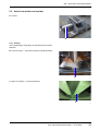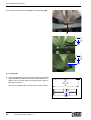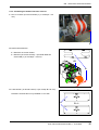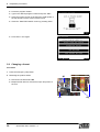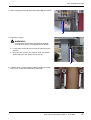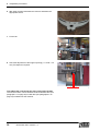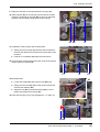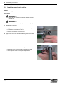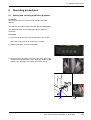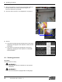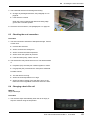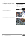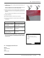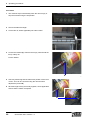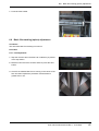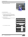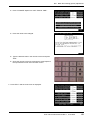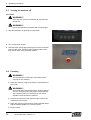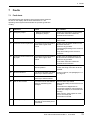
1
User manual
Quick Pack 350 / model 4 + 5
I
CE-Mark
This machine displays the CE-Mark. This means that this machine conforms with all European directives relating
to health and safety. A summary of these directives is included in the Declaration of Conformity supplied.
Liability
JASA packaging systems is not liable for any hazardous situations, accidents or damage resulting from:
■
The warnings or regulations shown on the machine or in the documentation being ignored.
■
Use for other applications or under conditions other than those described in this document.
■
Modifications to the machine. This also includes the use of any replacement parts other than the original
and alterations to the control program.
■
Inadequate maintenance.
JASA packaging systems cannot be held responsible for any damage resulting from faults in the machinery (e.g.
damage to products, operational delays).
All rights reserved - The duplication or the passing of this information to third parties in whatever form without
written permission Pannekeet Machinetechniek bv is forbidden.
Reservations - All descriptions, diagrams, illustrations and specifications apply to the machinery at the moment
of delivery. Pannekeet Machinetechniek bv reserves the right to carry out modifications at any time without having
to adapt this documentation.
© 2003 Pannekeet Machinetechniek bv
350-04-05 EN Rev. 1
II
Quick Pack 350 / model 4 + 5
Table of contents
Table of contents
Table of contents . . . . . . . . . . . . . . . . . . . . . . . . . . . . . . . III
1 Foreword . . . . . . . . . . . . . . . . . . . . . . . . . . . . . . . . . . . . . . 1
1.1 Aim . . . . . . . . . . . . . . . . . . . . . . . . . . . . . . . . . . . . . . . 1
1.2 Machine documentation and user . . . . . . . . . . . . . . . . 1
2 Safety . . . . . . . . . . . . . . . . . . . . . . . . . . . . . . . . . . . . . . . . .
2.1 Introduction . . . . . . . . . . . . . . . . . . . . . . . . . . . . . . . . .
2.2 Intended purpose of machine . . . . . . . . . . . . . . . . . . .
2.3 Safety provisions . . . . . . . . . . . . . . . . . . . . . . . . . . . .
2.4 Safety regulations . . . . . . . . . . . . . . . . . . . . . . . . . . . .
2.5 Emission of hazardous materials. . . . . . . . . . . . . . . . .
2.6 Disasters . . . . . . . . . . . . . . . . . . . . . . . . . . . . . . . . . . .
2.7 End of lifespan . . . . . . . . . . . . . . . . . . . . . . . . . . . . . .
3
3
4
5
7
8
9
9
3 General description . . . . . . . . . . . . . . . . . . . . . . . . . . . . 11
3.1 Machine description . . . . . . . . . . . . . . . . . . . . . . . . . 11
3.2 Options . . . . . . . . . . . . . . . . . . . . . . . . . . . . . . . . . . . 12
4 Controls . . . . . . . . . . . . . . . . . . . . . . . . . . . . . . . . . . . . . .
4.1 Controls . . . . . . . . . . . . . . . . . . . . . . . . . . . . . . . . . .
4.2 Control module . . . . . . . . . . . . . . . . . . . . . . . . . . . . .
4.3 Main menu screen . . . . . . . . . . . . . . . . . . . . . . . . . .
4.4 Sub-menu-screens . . . . . . . . . . . . . . . . . . . . . . . . . .
4.5 User menu screen . . . . . . . . . . . . . . . . . . . . . . . . . .
4.6 Overview menu screen . . . . . . . . . . . . . . . . . . . . . . .
4.7 Test menu screen . . . . . . . . . . . . . . . . . . . . . . . . . . .
4.8 Change basic film roll . . . . . . . . . . . . . . . . . . . . . . . .
4.9 Film belt menu . . . . . . . . . . . . . . . . . . . . . . . . . . . . .
4.10 Components menu . . . . . . . . . . . . . . . . . . . . . . . . . .
4.11 Password menu . . . . . . . . . . . . . . . . . . . . . . . . . . . .
17
17
21
22
22
22
25
26
28
29
29
29
5 Preparation procedures . . . . . . . . . . . . . . . . . . . . . . . . .
5.1 Installation and operation . . . . . . . . . . . . . . . . . . . . .
5.2 Select form holder and seal bar . . . . . . . . . . . . . . . .
5.3 Turning on machine . . . . . . . . . . . . . . . . . . . . . . . . .
5.4 Basic film transport . . . . . . . . . . . . . . . . . . . . . . . . . .
5.5 Label film transport . . . . . . . . . . . . . . . . . . . . . . . . . .
5.6 Positioning label film . . . . . . . . . . . . . . . . . . . . . . . . .
5.7 Setting the mark scanner . . . . . . . . . . . . . . . . . . . . .
5.8 Changing a format . . . . . . . . . . . . . . . . . . . . . . . . . .
5.9 Replacing a horizontal seal bar . . . . . . . . . . . . . . . .
31
31
33
37
38
43
46
48
56
60
6 Operating procedures . . . . . . . . . . . . . . . . . . . . . . . . . .
6.1 Starting and checking production preamble . . . . . . .
6.2 Checking production . . . . . . . . . . . . . . . . . . . . . . . . .
6.3 Checking the seal connection . . . . . . . . . . . . . . . . . .
6.4 Changing a basic film roll . . . . . . . . . . . . . . . . . . . . .
6.5 Changing the label film roll . . . . . . . . . . . . . . . . . . . .
6.6 Basic film tracking (option) adjustment . . . . . . . . . . .
6.7 Turning the machine off . . . . . . . . . . . . . . . . . . . . . .
6.8 Cleaning . . . . . . . . . . . . . . . . . . . . . . . . . . . . . . . . . .
61
61
62
63
63
65
67
70
70
7 Faults . . . . . . . . . . . . . . . . . . . . . . . . . . . . . . . . . . . . . . . . 73
7.1 Fault alerts . . . . . . . . . . . . . . . . . . . . . . . . . . . . . . . . 73
7.2 Faults summary . . . . . . . . . . . . . . . . . . . . . . . . . . . . 75
User manual 350-04-05 EN Rev. 1, 9-2-2006
III
Table of contents
8 Appendix . . . . . . . . . . . . . . . . . . . . . . . . . . . . . . . . . . . . . . 77
8.1 Technical details . . . . . . . . . . . . . . . . . . . . . . . . . . . .77
8.2 Film requirements, net . . . . . . . . . . . . . . . . . . . . . . . .78
8.3 Liability and guarantee . . . . . . . . . . . . . . . . . . . . . . . .78
9 Index . . . . . . . . . . . . . . . . . . . . . . . . . . . . . . . . . . . . . . . . .79
IV
Quick Pack 350 / model 4 + 5
1
1
Foreword
Foreword
1.1 Aim
This manual contains important procedures and practical tips
which will enable the packaging machine to be used safely,
efficiently and with reliability.
Should this manual fail to offer a solution for any technical faults,
please do not hesitate to contact the service department of
Pannekeet Machinetechniek bv. When doing so please mention
the machine number (1) and the number shown on this manual.
Any essential work to be carried out by the JASA packaging
systems personnel is not included in this manual.
Keep this documetation in a safe place.
Pannekeet Machinetechniek bv, will be referred to as JASA
packaging systems in the following text.
Hazenkoog 14,
1822 BS Alkmaar (Netherlands),
1
Telephone: +31 (0)72 - 56 12 700,
7 days per week from 0:00 - 24:00 h.
0001
Telefax: +31 (0)72 - 56 25 407
E-mail: [email protected]
1.2 Machine documentation and user
The machine documentation comprises:
■
User manual for the user. Information is also given on the
procedure to follow in the event of faults.
■
Maintenance manual for the maintenance technician.
■
Spare parts catalogue with diagrams for the maintenance
technician and the purchasing dept.
Subjects can be located using the table of contents or by
referring to the word index which shows the subjects in
alphabetical order.
User manual 350-04-05 EN Rev. 1, 27-2-2006
1
1
2
Foreword
Quick Pack 350 / model 4 + 5
2
2
Safety
Safety
2.1 Introduction
This machine has been designed and built in such a way as to
allow its safe use and maintenance. This applies to the
application, the conditions and the regulations as described in
this documentation.
It is essential that any individual working on the machinery
should read this documentation.
Any working activities not addressed in these instructions should
only be carried out by the appropriate expert personnel.
2.1.1 Warning symbol
WARNING!!!
When the above warning symbol is displayed together with the
relevant text, this displays information vital to the health and
safety of the personnel.
If these warnings are ignored, this may result in serious injury or
even have fatal consequences.
User manual 350-04-05 EN Rev. 1, 27-2-2006
3
2
Safety
2.2 Intended purpose of machine
The Quick Pack 350 / model 4 or Quick Pack 350 / model 5 has
been manufactured for the packaging of potatoes, vegetables
and fruit in bags. This bag is formed in the machine using a basic
film (1) with labelled film (2). "Netting with printed film" (3) may
also be used.
Furthermore, it is also possible to adapt this machine for the
packaging of foodstuffs in printed polythene, polypropylene or
laminated film.
This machine is not intended for any other use.
2
1
0002
3
0003
4
Quick Pack 350 / model 4 + 5
2.3
Safety provisions
2.3 Safety provisions
2.3.1 Emergency stop button
An emergency stop button (1) has been fitted to isolate the
machine as quickly as possible in the event of an emergency.
The button is easily identifiable by its red colour.
1
When the button is depressed the machine stops immediately.
The button is blocked mechanically and the machine cannot be
restarted.
It is now possible to administer immediate assistance following
an accident involving any personnel. Any other urgent action
should also be carried out forthwith.
The button may only be released only when any hazardous
situation has been dealt with satisfactorily. The machine will not
start immediately, but can now be started in the normal manner.
0004
The emergency button can also be used in the event of sudden
impending hazards e.g. faulty operation or the jamming of
material.
Recommendations
■
New operatives should be allowed an opportunity to
practice the use of the emergency stop button.
■
Do not use the emergency stop button as an alternative for
turning the machine off normally.
■
Test the emergency stop button regularly.
■
Do not reset the emergency stop button until it has been
established who has operated it and why.
2.3.2 Door
The door (2) is fitted with protective break contacts. When a door
is open the transverse seal unit ceases to function.
Mandatory instructions!!!
■
Never bypass the door contacts. This also applies during
service and maintenance work.
■
The correct functioning of the door contacts must be
tested at frequent.
2
0005
User manual 350-04-05 EN Rev. 1, 27-2-2006
5
2
Safety
2.3.3 Transverse seal unit
The transverse seal unit cylinder (3) is fitted with protective break
contacts. If the transverse seal unit develops a fault, the break
contacts will open the transverse seal unit.
WARNING!!!
The transverse seal unit is fitted with a knife and closes
very positively. These form an extreme hazard of
serious and permanent injury.
3
0006
2.3.4 Electrical motors
The electrical motors are protected against overloading. The
electrical motor switches off automatically when overloaded.
2.3.5 Warning stickers
There are a variety of warning stickers displayed on the machine.
These warning stickers may not be removed.
Any sticker that becomes loose or illegible should be replaced
immediately.
Caution: Rotating or moving machine parts.
Stay clear of these parts. It is strictly prohibited to
remove bags manually when the machine is running.
Caution: High voltage.
The electrical supply should be switched off and
locked before any maintenance or repair work is
carried out.
The control box may only be opened after the main
switch has been turn off and locked.
Caution: Personal injury!
Never place any body parts between moving
machinery parts.
Caution: Hot parts.
Never press the seal bars.
6
Quick Pack 350 / model 4 + 5
2.4
Safety regulations
2.4 Safety regulations
2.4.1 Technical condition
■
The machine has been built using the latest technology
and conforms to the rules of safety.
However, the use of this machine could result in personal
injury to the user, to third parties or to material objects.
This packaging machine should therefore only be used for
its recommended use when it technically faultless and all
appropriate regulations are observed.
■
Faults identified automatically by the control system
should be rectified immediately.
■
It is forbidden to make modifications to the packaging
machine without first obtaining written permission from
JASA packaging systems.
■
Ensure there is adequate light in the work area (approx.
80 lux).
Residual hazard
Despite all stated safety measures, this machine is dangerous to
operate. Failure to heed the recommendations for safe operation
will lead to situations that result in serious and permanent injury.
This applies to the transverse seal in particular. For this reason,
the placement of a discharge conveyor is mandatory. When
placing a discharge conveyor, it is vital that the customer takes
account of the dangers inherent in the transverse seal. A proper
safety shield should be incorporated in the system (see adjacent
photo).
2.4.2 Management
■
The management is obliged to properly train the personnel
who will be operating the machine, based on this manual.
■
Any essential work to be carried out on the packaging
machine should only be carried out by authorised
personnel.
■
Temporary personnel and trainees may only operate the
packaging machine while under the supervision and
responsibility of authorised personnel.
■
Functions, authorisation and responsibility of the
personnel should be clearly defined.
■
Regular checks should be made to ensure that work is
being carried out in accordance with the regulations.
2.4.3 Operation and maintenance
■
Operate and maintain the machine in accordance with the
machine documentation supplied.
This manual should be clearly visible at the packaging
machine site.
■
Observe all JASA packaging systems safety regulations
when working with the packaging machine. All local
regulations should also be observed.
User manual 350-04-05 EN Rev. 1, 27-2-2006
7
2
Safety
■
Safety provisions may not be removed or rendered
inactive.
■
Always wear safety clothing and industrial shoes.
■
Always wear protective gloves when replacing the knives
of the transverse seal.
■
Do not wear any rings, watches or loosely fitting articles of
clothing. These may become entangled in moving
machine parts.
■
Never carry loose objects in clothing pockets.
■
Long hair should be bound together.
■
Use any agents, e.g. cleaning agents in accordance with
the manufacturer's instructions.
■
Before turning the machine on:
•
Make sure all unauthorised personnel are well away
from the machine.
•
Inform authorised personnel in the vicinity of the
machine and ensure that all personnel are well away
from any moving parts.
•
Ensure that all safety provisions are in place and that
they are effective.
■
Production should remain within the confines described in
the technical specifications.
■
Maintenance work should only be carried out after the
work area has been clearly marked.
Maintenance should only be carried out on a machine that
is:
•
Switched off, with the main switch locked.
•
Disconnected from the compressed air supply and
depressurised.
■
Never use defective tools.
Tools should be used only for their intended use.
■
Wear safety glasses and take extra care when working
with compressed air.
■
Special care should be taken when using lifting equipment,
using only reliable and approved lifting gear and
attachments.
■
On completion of lifting activities checked that all tools,
rags etc have been removed from the machine and and
the work area.
2.5 Emission of hazardous materials.
The actual machine does not contain any materials that could
present a hazard to individuals.
All material used in the production process would not be
expected to emit hazardous materials.
8
Quick Pack 350 / model 4 + 5
2.6
Disasters
The machine is not capable of limiting any risks presented by the
emission of hazardous materials. If products are to be used that
may contain hazardous materials supplementary measures
should be taken.
2.6 Disasters
There are no special regulations applicable to disasters.
The usual extinguishing system can be used.
2.7 End of lifespan
If the machine is to be dismantled at the end of its lifespan, the
regulations that apply to waste disposal at the time of dismantling
should be observed.
Only familiar materials have been used in the machine's
manufacture.
At the time of manufacture there were waste processing options
in place and there were no recognised risks present for any
personnel involved in the dismantling work.
User manual 350-04-05 EN Rev. 1, 27-2-2006
9
2
10
Safety
Quick Pack 350 / model 4 + 5
3
3
General description
General description
3.1 Machine description
The machine packages products in bags that are formed from
lengths of film. The film is supplied from a roll (2) to the film
accumulator (1). The film accumulator (1) ensures that the
unrolling of the film (2) is controlled and is supplied at a constant
tension to the form shoulder (3).
1
2
0007
The form shoulder (3) surrounds the product infeed (4) which
supplies the product to be packaged. The form shoulder (3) and
product infeed (4) together form one module. The shape and size
of the module depends on the product to be packaged and the
bags to be produced.
3
4
0008
The film is transported by two drive belts (5).
The film is wide enough to leave an overlap after surrounding the
product infeed. The vertical seal bar is used for (6) forming a seal
on the overlap.
5
6
5
0009
User manual 350-04-05 EN Rev. 1, 27-2-2006
11
3
General description
After the product has been released, the side folding mechanism
folds (8) the sides of the bag inwards.
The seal bars (7) seal the top and bottom of the bag. The lower
seal bar is fitted with a cutting edge that cuts the foil.
The size and shape of the seal bar depends on the bags to be
processed.
The machine is operated and monitored by a digital control
system.
8
7
0010
3.2 Options
A number of options allow this machine to be extended.
3.2.1 Label film unit
The label film unit makes it possible to apply a label film to the
front and back side of the bags.
1
A roll of label film (2) is attached to the side of the machine.
There is a film accumulator (3) behind the label film roll (2) that
controls the unrolling of the film roll.
The film is cut into two equal pieces with a cutting edge (4). The
seal bars (1) seal the the film to the bag film.
2
3 4
0011
12
Quick Pack 350 / model 4 + 5
3.2
Options
3.2.2 Attach a carrying handle
This machine can fitted with an extra seal bar for attaching a
carrying handle to the bags.
A variety of carrying handles are available.
1 Euroslot.
2 Hand grip.
3 Finger grip.
1
2
3
0012
3.2.3 Counter
The counter can be used for the accurate measurement of a bag,
for example.
The counter can also be used to turn on the mark scanner within
a defined area.
0013
User manual 350-04-05 EN Rev. 1, 27-2-2006
13
3
General description
3.2.4 Printer
The printer is used for printing information onto the packaging
(such as "use by" dates and barcodes). The printer is fitted into a
holder that can be adjusted in two directions. The holder is
symmetrical and can be attached to either the left-hand or the
right-hand side of the label film or above the basic film. It is also
possible to use two printers.
0014
3.2.5 Bag vibrator
A bag vibrator condenses the product in the packaging. The
machine height may be ± 200 mm depending on the longest bag
to be produced.
3.2.6 Basic film control
The basic film control ensures that irregularly wound film is fed
into the machine automatically.
0015
3.2.7 Basic film seal unit
The basic film seal unit seals a new piece of basic film to the end
of the piece already in the machine.
0016
14
Quick Pack 350 / model 4 + 5
3.2
Options
3.2.8 Import buffer belt - export belt
Import buffer belt
The import buffer belt collects the product and introduces it
horizontally into the infeed.
0017
Export belt
Both belts are driven by the packaging machine.
WARNING!!!
Beware of moving parts. These can cause serious
injury.
0018
User manual 350-04-05 EN Rev. 1, 27-2-2006
15
3
16
General description
Quick Pack 350 / model 4 + 5
4
4
Controls
Controls
4.1 Controls
Main switch with locking option
0019
Control module with emergency stop button
The emergency stop button interupts an electrical circuit at the
moment it is depressed. This will also cause an emergency stop
relay to trip if there is a break in the conductor.
During the activation of an emergency stop circuit:
■
The compressed air system is decompressed except for
the brake cylinders and the pressure vessel.
■
All voltages in excess of 24VDC are switched off.
After pressing the emergency stop button, reset it (depending on
the model) either by turning the button in the direction of the
arrow, or pressing it once more, or pulling on it.
0020
User manual 350-04-05 EN Rev. 1, 27-2-2006
17
4
Controls
Manual controls of the connection seal
0021
Mark scanner
A MARK is determined using the contrast value of the mark.
B BKGD is determined using the contrast value of the
background.
B
A
0022
Basic film seal unit (option)
A Seal time.
C
B Cooling time.
C Starting: following preparation, push down the seal bar.
A
B
0023
18
Quick Pack 350 / model 4 + 5
4.1
Controls
Sideways adjustment of basic film roll (not available with
automatic basic film control (option))
0024
Label film catch
0025
The readings are used for setting the:
Loop length of the basic film enabling it to be cut off at the mark.
0026
Loop length of the label film enabling the synchronisation of the
front and back pieces of film.
0027
User manual 350-04-05 EN Rev. 1, 27-2-2006
19
4
Controls
Transverse position of the label film.
0028
Printer height.
0029
Pneumatic:
A Basic film tension.
B Basic film transport (unrolling speed of basic film).
A
B
0030
20
Quick Pack 350 / model 4 + 5
4.2
Control module
Button to clean filter.
0031
4.2 Control module
The control module comprises:
■
An emergency stop button (1).
■
A touch screen display (2).
■
4 control indicators (3 up to and including 6).
■
3 buttons (7 up to and including 9).
1
2
4.2.1 Control indicators
Power indicator (3)
Main switch activated.
Start indicator (4)
Production. When flashing: start indicator waiting for weighing
machine.
0032
Stop indicator (5)
Machine stops at the end of the cycle.
3 4
5
6
Reset indicator (6)
Alarm alert.
4.2.2 Buttons
Reset button (7)
Resets controls.
Stop button (8)
Stops selected function.
9
8
7
0033
Start button (9)
Starts selected function.
User manual 350-04-05 EN Rev. 1, 27-2-2006
21
4
Controls
4.3 Main menu screen
After starting the machine the main menu is displayed on the
screen.
From the main menu, a choice can be made from the following
sub-menus by pressing the appropriate text on the screen.
The main menu consists of 7 sub-menus.
These are:
■
USER SETTINGS (see paragraph 4.5 on page 22).
■
OVERVIEW (see paragraph 4.6 on page 25).
■
TEST (see paragraph 4.7 on page 26).
■
FILM CHANGE (see paragraph 4.8 on page 28).
■
FILM BELTS (see paragraph 4.9 on page 29).
■
COMPONENTS (see paragraph 4.10 on page 29).
■
PASSWORD (see paragraph 4.11 on page 29).
BC0102
The composition of the sub-menus are described below.
4.4 Sub-menu-screens
Press the word "CHANGE" to change the settings on the user
menu. If the word "CHANGE" is not displayed, press the actual
value to remove it. On the displayed numeric screen, type in the
new desired value and activate this value by pressing "ENT". The
selected value will appear in the display bar. Close the menu by
pressing the square in the top left-hand corner of the numeric
screen.
The previous menu can be reselected by pressing "ESC".
4.5 User menu screen
BC0103
22
Quick Pack 350 / model 4 + 5
4.5
User menu screen
4.5.1 TIMES AND LENGTHS MENU
Altering the time that the packaging machine requires to carry out
the different processes.
BC0106
BC0107
SEAL TIME HORIZONTAL
The length of time that the horizontal seal jaws are closed.
SEAL TIME VERTICAL
The length of time that the vertical seal bar is applied to the film.
This time display stops when the horizontal seal jaws are
opened. The vertical seal bar is opened.
CONNECTION SEAL
The length of time that the connection seal is applied to the film.
COOLING TIME
A stream of cool air is emitted during the opening of the
horizontal seal jaws.
FILM LENGTH
Length of the film. This value is determined by the machine setup.
WAIT BEFORE FILM TRANSPORT
Waiting time from the opening of the horizontal seal jaws until the
start of the film transport.
WAIT AFTER PACKAGE
Waiting time between the end of one packaging operation and
the start of the next packaging operation.
User manual 350-04-05 EN Rev. 1, 27-2-2006
23
4
Controls
ADVANCE DROP MOMENT
If this time is displayed as 0.00 the machine will close the seal
jaws. If a time is set, a product will be dropped earlier and will be
released from the horizontal seal jaws earlier.
NUMBER OF DROPS IN A BAG
The desired number of drops into one packaging.
NET TRACKING TIME
Used for the film control. Everytime that the film transport is
started the film is checked for correct adjustment. If this not the
case, the film position will be corrected during this time.
EMPTY SPACE FOR MARK
This is used if an undesirable print is between the mark stripes on
the film. If a value between 35 and 99 mm is set, the mark
scanner will only be active from the set distance in front of the
mark stripe.
4.5.2 TEMPERATURE CONTROL MENU
Temperature settings for the various seals.
The temperature can be changed by pressing the temperature
value.
BC0150
BC0151
4.5.3 LOAD SETTINGS
Retrieval of saved settings.
BC0104
24
Quick Pack 350 / model 4 + 5
4.6
Overview menu screen
4.5.4 SAVE SETTINGS
Save selected settings.
BC0105
4.6 Overview menu screen
BC0159
MAIN OVERVIEW
The various values of the machine settings are displayed.
BC0160
TEMPERATURE OVERVIEW
A list of the temperaures of the various machine components.
BC0161
User manual 350-04-05 EN Rev. 1, 27-2-2006
25
4
Controls
PRODUCTION SPEED
The production time in bags/min is displayed.
BC0162
STATISTICS
The production values are displayed.
Press "RESET" to reset the day counter on the menu.
BC0163
BC0164
4.7 Test menu screen
SINGLE BAG CYCLE TEST
The single cycle test activates one test cycle.
CONTINUOUS BAG CYCLE TEST
A number of test cycles are performed when continuous test
cycle is selected.
BC0146
26
Quick Pack 350 / model 4 + 5
4.7
Test menu screen
TEST BASIC FILM CONTROL
The basic film control test enables the film roll to be controlled
manually from either the left or the right. If its working range is
exceeded it will stop and one of two "end sensors" will be
illuminated.
BC0149
TEST CONNECTION SEAL
The connection seal test allows the connection seal to be used
manually.
BUFFER TEST
■
FILL BUFFER.
■
EMPTY BUFFER.
BC0148
COUNTER
The counter tests if the machine is measuring the film transport.
BC0167
User manual 350-04-05 EN Rev. 1, 27-2-2006
27
4
Controls
4.8 Change basic film roll
FILM CHANGE
Selecting "FILM CHANGE" in the basic menu will activate the
change basic film roll cycle. This happens in three stages
following instructions displayed on the screen.
BC0170
BC0171
BC0172
BC0173
28
Quick Pack 350 / model 4 + 5
4.9
Film belt menu
4.9 Film belt menu
FILM BELTS
Selecting "OPEN" from the "FILM BELTS" sub-menu opens the
belt and allows manual transport. The "MANUAL FILM
TRANSPORT" allows the belt to be operated by hand.
BI0166
4.10 Components menu
COMPONENTS
Using the "COMPONENTS" sub-menu, the machine
components can be turned on and off independently of each
other.
During production "HAND GRIP HEATING" or "HEATING
CONN. SEAL" can be selected to preheat the seals.
BI0165
4.11 Password menu
PASSWORD
Level 2 of the menu will open on entry of a password in the
"PASSWORD" menu.
The extended level 2 is not addressed within this user manual.
BC0176
User manual 350-04-05 EN Rev. 1, 27-2-2006
29
4
30
Controls
Quick Pack 350 / model 4 + 5
5
5
Preparation procedures
Preparation procedures
5.1 Installation and operation
5.1.1 Installation
Condition
The machine packaging is undamaged on delivery.
Procedure
1 Install the machine on a sturdy base e.g. concrete.
2 Install the machine in accordance with the placement
diagram.
Use the lifting eyes or a fork lift truck.
WARNING!!!
Take care when using block and tackle equipment.
Use only suitable and approved lifting gear and
attachments.
It is forbidden to stand under a suspended load.
3 Adjust the machine using the adjustable feet:
■
Level.
■
A machine with liquid waste pipe: sloping towards the
waste gulley, maximum 5 mm/m.
0034
4 Connect the compressed are supply in such a manner that
the supply can be switched off and the packaging machine
can be depressurised. E.g. with a quick-coupler.
5 Connect the machine in accordance with the electrical
diagram.
5.1.2 Operation
6 Check that the phases of the electrical supply are connected
correctly. Turn on the film transport and check the direction of
rotation.
0035
User manual 350-04-05 EN Rev. 1, 27-2-2006
31
5
Preparation procedures
7 Check that the installed options are operational.
8 Set the Synchro-settings:
■
Weighing machine ready / Jasa acknowledges, (P7.7 in
Newtec loose. Jasa Synchro-setting at 0):
When the weighing machine has a drop ready in its
weighing trays it gives a “ready signal”. This signal will
continue until Jasa gives an "acknowledgment". The
“acknowledgment” is a pulse of 200 msec.
When the weighing machine receives the
“acknowledgment” it releases its drop and removes the
"ready signal".
■
BI0102
Jasa Ready to receive / Weighing machine dropped, (P7.7
in Newtec fixed. Jasa Synchro-setting at 1):
If the Jasa is ready to receive a drop it gives a "ready to
receive signal". This signal is continuous until the weighing
machine gives its "dropped signal". The “drop signal” is a
pulse of 200 ms. When the weighing machine receives the
"ready to receive signal" and it has a drop in its weighing
trays, it releases its load and gives the "dropped signal".
The Jasa removes the "ready to receive signal" on receipt
of the "dropped signal".
Without advancing the dropping time, without advancing
the sealing jaws, and without buffer and collection belts.
The Jasa starts a bag cycle by closing the seal jaws as
soon as the weighing machine releases a portion. The
weighing machine may resume its drops when the bag
cycle is complete.
9 Go to level 1.
BC0102
32
Quick Pack 350 / model 4 + 5
5.2
Select form holder and seal bar
5.2 Select form holder and seal bar
A Format.
A
0036
5.2.1 Overlap
The intended bag overlap plays an important part in format
selection.
B Left over right (L – R) and a-symmetrical (with label film).
B
0037
C Right over left (R – L) and symmetrical.
C
0038
User manual 350-04-05 EN Rev. 1, 27-2-2006
33
5
Preparation procedures
D Universal form shoulder for bag (D1) or laminate bag (D2).
D
0039
D1
0040
D2
0041
5.2.2 Bag width
E The bag width (X) [mm] is the size when laid flat and excludes
side pleat (E1). The maximum bag size for this machine is
350 mm, when a bag is made using label film the maximum
bag width is 340 mm.
The format is signified with a number X, the format number.
E
Y
X
E1
0042
34
Quick Pack 350 / model 4 + 5
5.2
Select form holder and seal bar
5.2.3 Calculating the width of the basic film roll
F Film or Vertisac: (2x format number) + (1x overlap Y = 30
mm).
F
0043
G Net film with label film:
■
Maximum 2x format number.
■
Minimum (2x format number) – (film width label film
exterior G1) + (2x overlap Y = 30 mm).
G1
G
0044
H Laminate film: (2x format number) + (2x overlap Z = 20 mm).
L–R
Remarks: Laminate film is only sealable on one side.
Z
X
H
R–L
Z
X
0045
User manual 350-04-05 EN Rev. 1, 27-2-2006
35
5
Preparation procedures
5.2.4 Format
The maximum format for this machine is 350 or 340 mm for an
asymmetrical format. Formats for all other bag widths are
available on application. The following points are important:
■
The overlap (R – L) or (L – R).
■
A-symmetrical (with label film) or symmetrical.
■
For laminate, for laminate and film or film.
5.2.5 Connection seal bar and vertical seal bar versions
■
PE - 3 mm.
■
PE or laminate - 6 mm.
■
Laminate or PP - 8 mm.
0046
5.2.6 Horizontal seal bar versions
Length 280 of 380 mm. The selection depends on the format
number and if the bags are to be produced only with side pleat.
■
PE or extruded net - 3 mm (I1).
■
Laminate - 3 mm, 6 mm, coarse serration or 3 x 3 mm (I2).
■
PP - fine serration (I3).
■
Claf + label film - 12 mm (I4).
I1
I2
I3
I4
0047
36
Quick Pack 350 / model 4 + 5
5.3
Turning on machine
5.3 Turning on machine
Tools
Soft cloth.
Procedure
1 Check the following points before the machine is used for the
first time:
■
For damage.
■
If all parts and accessories are present.
■
The correct operation of the controls.
2 Check that the fitted seal bars are suitable for use with the film
type to be used (see paragraph 5.2.6 on page 36).
3 Check the teflon (A1) and if fitted A2 for damage and wear.
The fibres of the protective layers may not be visible and
there should be no evidence of loose teflon particles. Inspect
the rubber background for damage and thickness uniformity.
A1
A2
0048
4 Inspect the teflon layer at the connection seal bar and at the
vertical seal bar. Make the necessary adjustments if there are
signs of wear.
5 Close the doors.
0049
User manual 350-04-05 EN Rev. 1, 27-2-2006
37
5
Preparation procedures
6 Clean the reflectors and infeed (option) photocells with a soft
cloth.
0050
7 Turn on the power.
0051
8 Reset the machine: release the emergency stop button (B)
then press “reset” and “OK” (see paragraph 4.1 on page 17).
B
0052
5.4 Basic film transport
Condition
The machine is on.
The basic film roll is changed.
38
Quick Pack 350 / model 4 + 5
5.4
Basic film transport
Tools
Scissors.
WARNING!!!
Foil feeding takes place with foil belts running. The
running belts can cause serious and permanent injury.
Procedure
1 In the main menu press “FILM CHANGE”. Press “Start Film
Change”, then move to step 2 via the next screen. The “FILM
CHANGE Step 2” screen is displayed.
2 Open the doors.
3 Remove any remaining film from the machine.
BC0172
4 Open the film belt: press “FILM BELTS” and then press
“OPEN”.
BI0166
5 Feed the basic film through the machine up to the format.
Film path (A) with basic film seal unit (option).
A
0053
User manual 350-04-05 EN Rev. 1, 27-2-2006
39
5
Preparation procedures
6 Pull out approximately 1 metre of the basic film.
0054
7 Cut the basic film at 45º from left to right.
0055
8 Lie the resulting point of film over the shoulder.
0056
9 Take the point (right-hand) and pull it out slightly further.
10 Place your left hand behind the film until it is just under the
edge.
0057
40
Quick Pack 350 / model 4 + 5
5.4
Basic film transport
11 Hold the basic film taught with your right hand and fold the
basic film backwards with your right hand.
12 Thread the folded part of the basic film between the shoulder
and the infeed. Push the basic film through firmly and
carefully until the point appears.
0058
13 Take the point (left hand), pull it out carefully until the basic
film appears at the top right hand side.
0059
14 Take the folded section of the basic film in your right hand.
Then pull carefully from left - right - left - right etc.
0060
15 Pull the basic film downwards.
0061
User manual 350-04-05 EN Rev. 1, 27-2-2006
41
5
Preparation procedures
16 Close film belts: Press “CLOSE" on the “FILM BELTS” screen.
Then press “ESC” and go to step 3 via the next screen. The
“FILM CHANGE Step 3” screen is displayed.
BC0173
17 Basic film transport: press “FILM BELTS”, then press
“MANUAL FILM TRANSPORT”. Keep this pressed in until the
edge of the film runs true. Then press “ESC” twice to return to
the main menu.
BI0166
18 Check that both film edges correspond with each other. If the
difference is more than 7 mm, make the necessary roll
adjustment (B1 (or B2 (option), see paragraph 6.6 on page
67)) and repeat step 17 of the procedure.
19 If label film is to be used; introduce this into the machine (see
paragraph 5.5 on page 43) and position correctly (see
paragraph 5.6 on page 46).
20 Close the doors.
B1
B2
0062
42
Quick Pack 350 / model 4 + 5
5.5
Label film transport
21 If the bag is cut over the mark; check this. Make any
necessary adjustments.
0063
5.5 Label film transport
Condition
The machine is on.
The label film roll has been changed.
Tools
Measuring tape.
Procedure
1 Check that the connection seal and the connection seal bar
heating is turned on.
2 Adjust both side guides from the centre outwards to within
+ 1 mm of the label film roll width.
0064
User manual 350-04-05 EN Rev. 1, 27-2-2006
43
5
Preparation procedures
3 Open the film belt: press “FILM BELTS” and then press
“OPEN”.
BI0166
Brake A is released.
A
0065
44
Quick Pack 350 / model 4 + 5
5.5
Label film transport
4 Pass the label film through the machine up to the cutting edge
(B).
C
Note: Lift the film-accumulator to its maximum height, this
simplifies the film transport.
B
5 Guide the label film carefully around the roll at the cutting
edge position. Then pull out the label film evenly for (± 1,5
meter). The cutting edge cuts the label film in two lengths.
WARNING!!!
D
Never touch the cutting edge from behind!
6 Pass the outer length over the return bar and under the basic
film. Continue to pass this outer length until it is under the
connection seal bar (C).
WARNING!!!
Never touch the hot seal bar.
0066
7 Making a connection seal: press the button E1 or press
"TEST CONN. SEAL" on the “FILM BELTS” screen. Then
release the film from the seal bars (E2).
WARNING!!!
The connection seal unit closes, avoid jamming!
The depression time is the seal time!
E1
8 Pass the middle length of film around the loop rolls and
around the return bar (D).
0067
E2
0068
9 Hold this length of film taught and check if both lengths are
equal. If not, make the necessary roll adjustment (F) and recheck.
10 Pass the middle film length under the basic film up to the
connection seal bars. Then carry out step 7.
F
11 Close the film belts by pressing "CLOSE" on the "FILM
BELTS" screen. Then press “ESC” to return to the main
menu.
0069
User manual 350-04-05 EN Rev. 1, 27-2-2006
45
5
Preparation procedures
5.6 Positioning label film
Condition
The label film is passed through the machine.
Procedure
1 Press "TEST" on the menu. Then press “CONTINUOUS BAG
CYCLE TEST”.
BC0146
2 Film transport: Press the Start button (A) and wait until the
film B is stationary. Then press the Stop button (C).
A
C
0070
B
0071
46
Quick Pack 350 / model 4 + 5
5.6
Positioning label film
3 The middle section of the label film should be in the centre of
the last bag (C1).
D3
Adjust the return bar as required (C2) and repeat points 2 and
3.
D2
4 The outside section of the label film should be immediately
opposite the centre section of the last bag (D1).
Adjust the return bar as required (D2) and make any
necessary adjustments to the connection seal bar (D3).
Repeat points 2 and 4.
C2
D1
C1
0072
5 Press "ESC" on the “TEST” screen.
BC0146
6 The pattern on the outer and centre film section should
match. If not, adjust the roll (E) and recheck.
E
0073
User manual 350-04-05 EN Rev. 1, 27-2-2006
47
5
Preparation procedures
5.7 Setting the mark scanner
The mark scanner is used to determine the length of the film by
using the marks that are printed on the film. Because the film
printing is optional, a choice can be made from 3 different
settings.
5.7.1 Counter
If there are no marks printed on the film, the length of the film will
be determined by the counter. The machine should be set for
length measurement using the counter. The counter measures
the passage of the film transport and makes gradual adjustments
to the length as required.
5.7.2 Mark scanner
If the mark scanner is selected, the length is determined by the
marks on the film. If a converted transport time which includes a
margin for error elapses without detecting a mark, the packaging
machine will stop and an error message will be displayed.
5.7.3 Mark scanner with counter.
This selection can only be selected if the machine is equipped
with a counter.
If the mark scanner with counter is selected, the length of the film
will be determined by the marks on the film. This option can be
selected if the film contains printing within the marks that can be
recognised by the scanner. The measurement of the film roll
displacement allows the mark location to be determined with
greater accuracy. Intermediate marks have therefore no
influence.
5.7.4 Procedure for setting the mark scanner.
1 Check that the light aperture of the mark scanner is located in
the path of the marks. Adjust as required.
0074
48
Quick Pack 350 / model 4 + 5
5.7
Setting the mark scanner
2 Position the label film so that the light aperture illuminates the
mark field.
0075
3 Without disturbing the label film press the button located
below the green indicator (ready) until the indicator is
extinguished.
4 Position the film so that the light aperture no longer
illuminates the mark field.
5 Without disturbing the label film press the button located
below the red indicator (out) until the green indicator
illuminates briefly and then extinguishes.
The green indicator will be continuously illuminated when the
mark scanner is set correctly.
0076
If the indicator flashes slowly, the setting procedure has failed.
A rapidly flashing indicator is an indication that the photocell
has short-circuited or is overloaded.
An extinguished indicator means that the photocell is not
energised or that the grey value has been achieved.
6 Turning the mark scanner on.
■
Press “COMPONENTS” on the main menu screen.
BC0102
User manual 350-04-05 EN Rev. 1, 27-2-2006
49
5
Preparation procedures
■
Press "OUT" adjacent to “MARK SCANNER”. The mark
scanner is turned on.
BI0165
■
Press “ESC” to close the components menu.
BI0165
Note: Point 7 does not apply to “MARK SCANNER WITH
COUNTER”.
7 Film length.
■
Press “USER SETTINGS”.
BC0102
■
Press “ADJUST TIMES AND LENGTHS”.
BC0103
50
Quick Pack 350 / model 4 + 5
5.7
■
Setting the mark scanner
Press "CHANGE" adjacent to "FILM LENGTH".
BC0106
■
Press the value to be changed.
BC0119
■
Type in the film length on the numeric screen + 10 mm and
activate this value by pressing “ENT”.
■
Close the numeric screen by pressing the small square in
the top left-hand corner of the numeric screen.
0077
■
Press “ESC” until the main menu is displayed.
BC0119
User manual 350-04-05 EN Rev. 1, 27-2-2006
51
5
Preparation procedures
Note: Point 8 only applies to “MARK SCANNER WITH
COUNTER”.
8 Film length.
■
Press “USER SETTINGS”.
BC0102
■
Press “ADJUST TIMES AND LENGTHS”.
BC0103
■
Press “ADDITIONAL SETTINGS”.
■
Measure the distance between the end of the printed field
and the start of the mark using a measuring tape. This
should be a minimum of 35 mm. If this distance exceeds
99mm, please enter 99 mm.
BC0106
■
Press "CHANGE" adjacent to “EMPTY SPACE FOR
MARK”.
BI0107
52
Quick Pack 350 / model 4 + 5
5.7
■
Setting the mark scanner
Press the value to be changed.
BC0128
■
Type the measured value on the numeric screen and
press “ENT”.
■
Close the numeric screen by pressing the small square in
the top left-hand corner of the numeric screen.
■
Press “ESC”.
0078
■
Press "CHANGE" adjacent to "FILM LENGTH".
BC0106
■
Press the value to be changed.
BC0119
User manual 350-04-05 EN Rev. 1, 27-2-2006
53
5
Preparation procedures
■
Type the exact film length on the numeric screen and
press “ENT”.
■
Close the numeric screen by pressing the small square in
the top left-hand corner of the numeric screen.
0079
■
Press “ESC” until the main menu is displayed.
BC0119
9 Producing bags.
■
Press "TEST" on the menu.
BC0102
■
Press “SINGLE BAG CYCLE TEST”.
BC0146
54
Quick Pack 350 / model 4 + 5
5.7
■
Press the start button twice to start the test cycle.
■
Check the film length.
Setting the mark scanner
0080
■
Press "ESC” or adapt the data as required.
BC0146
10 Save program.
■
Press “USER SETTINGS”.
BC0102
■
Press “SAVE CURRENT SETTINGS".
BC0103
User manual 350-04-05 EN Rev. 1, 27-2-2006
55
5
Preparation procedures
■
Press the program number.
■
Type in the desired program number and press “ENT”.
■
Close the numeric screen by pressing the small square in
the top left-hand corner of the numeric screen.
■
Close the ”SAVE SETTINGS" screen by pressing “ESC”.
BC0105
■
Press “ESC” once again.
BC0103
5.8 Changing a format
Procedure
1 Press the emergency stop button.
2 Releasing the product infeed:
■
Disconnect the bar A1 and A2.
■
A3 pull the film belt out, tear the film open and push it to
the rear.
A1
A2
A3
0081
56
Quick Pack 350 / model 4 + 5
5.8
Changing a format
3 When using larger formats: rotate the support (B) as required!
B
0082
4 Replacing a format:
WARNING!!!
Avoid damage from shocks and careless handling.
A format is too heavy to be handled by one person!
■
Loosen both screws (C) and remove the format from the
machine.
■
Place the new format in the machine, slide into position
against the stays and replace the screws (C).
C
0083
5 Visually check to ensure that the infeed is parallel to the film
belts. If not, contact the maintenance technician.
0084
User manual 350-04-05 EN Rev. 1, 27-2-2006
57
5
Preparation procedures
6 With other formats: Dismantle the crescent and attach the
appropriate format.
0085
7 Fix the bar.
0086
8 Check the adjustment of the support opening (> 1.0 and < 2.0
mm). Re-adjust as required.
0087
Only adjust the vertical seal bar when using other formats
The correct location can be determined when the basic film (see
paragraph 5.4 on page 38) or label film (see paragraph 5.5 on
page 43) is loaded into the machine.
58
Quick Pack 350 / model 4 + 5
5.8
Changing a format
9 Adjust the seal bar to correspond with the seal join (D).
10 Adjust support (E1) to correspond with the seal bar. Rotate
inwards or outwards as required (E2) so that it is supported
together with the seal bar against the product infeed.
E1 E2
D
0088
11 Parallelism of the bar (F1) with the back plate:
■
Gently push the bar (F1) against the product infeed and
measure the distance from the bar to the back plate in two
locations.
■
If the bar is not parallel (F2) adjust and remeasure.
12 Check that the vertical seal bar faces the centre of the product
infeed. Adjust as required (G).
F1
G
F2
0089
13 Bar adjustment:
H1
■
Loosen the fixings (H1) and push the rod (H2) back.
■
Gently push the bar (H3) against the product infeed and
measure the distance (H4).
■
Adjust the bar (H3) so that the distance (H4) is 10 mm
greater and retighten the fixings (H1).
14 Reset the emergency stop (see paragraph 4.1 on page 17).
H4 H2
H3
0090
User manual 350-04-05 EN Rev. 1, 27-2-2006
59
5
Preparation procedures
5.9 Replacing a horizontal seal bar
Material
Heat conducting paste.
Procedure
WARNING!!!
Even after the machine is switched off, the seal bars
are still hot.
WARNING!!!
One of the seal bars is equipped with a cutting edge
1 Dismantling a seal bar:
■
Apply even pressure to the spring, or use the tool supplied.
■
Lift the spring carefully over the lip.
■
Remove the seal bar from its holder.
2 Apply a thin even layer of heat conducting paste to the inside
of the new seal bar.
0091
3 Attach the seal bar:
■
Place the seal bar in the seal unit against the seating.
■
Return the spring symmetrically to its place by hand.
■
If this requires some force, repeat the procedure.
0092
60
Quick Pack 350 / model 4 + 5
6
6
Operating procedures
Operating procedures
6.1 Starting and checking production preamble
Conditions
The machine is turned on and the user settings have been
entered.
The basic film is loaded together with label film where applicable.
The equipment used for transporting products is ready for
production.
Procedure
1 Check that both film rolls are firmly attached to the spindle.
When fitted, the pinion locks as the film is unrolled.
2 Starting production: push the start button.
0093
3 Check that both film edges correspond with each other. If the
film deviation is greater than 7 mm, adjust the roll (A1 (or A2
(option), see paragraph 6.6 on page 67)) and re-check.
A1
A2
0094
User manual 350-04-05 EN Rev. 1, 27-2-2006
61
6
Operating procedures
4 When using label film: Check that the transversal position of
the roll is correct. This can be corrected using the roll
transverse adjustment (screws B).
5 Check the seal connection, see paragraph 6.3 on page 63.
0095
B
0096
6 Check if:
■
The drops are ready when the seal jaws close. This can be
adjusted by changing the value adjacent to “WAIT AFTER
PACKAGE”.
■
The product is received by the seal jaws. This can be
adjusted by changing the value adjacent to “ADVANCE
DROP MOMENT”.
BC0106
6.2 Checking production
Procedure
Check at least once a day:
WARNING!!!
Even after the machine is switched off, the seal bars
are still hot.
WARNING!!!
One of the seal bars is equipped with a cutting edge.
62
Quick Pack 350 / model 4 + 5
6.3
Checking the seal connection
1 The horizontal seal bars for damage and soiling.
■
Change any damaged seal bars, see paragraph 5.9 on
page 60.
■
If the seal bar is soiled:
Clean the warm horizontal seal bars and cutting edge
groove with a wooden spatula.
2 Check the seal connection, see paragraph 6.3 on page 63.
0097
6.3 Checking the seal connection
Procedure
1 The seal connection should be of adequate strength. If this is
not the case:
■
Increase the seal time.
■
And/or increase the cooling time.
■
And/or increase the seal temperature.
■
And/or check the system air pressure.
■
If the film seals poorly, load a new roll.
2 The seal surface may not become too hot. This will be evident
if:
■
Polythene (PE): the seal joint creases together or melts.
■
Polypropane (PP) or laminate: the seal joint is deformed.
Possible causes:
■
The seal time is too long.
■
And/or the seal temperature is too high.
■
And/or the teflon coating of the seal bar is worn or the
teflon film of the longitudinal connection seal bar is worn.
6.4 Changing a basic film roll
Material
Single-sided tape.
Procedure
1 The machine stops automatically when the roll is empty or
stop the machine using the stop button.
0098
User manual 350-04-05 EN Rev. 1, 27-2-2006
63
6
Operating procedures
2 Changing the basic film roll: press “FILM CHANGE" on the
main menu, then press “Start Film Change”. The “FILM
CHANGE Step 1” screen is displayed.
3 Cut the film off at the roll.
BC0171
4 Loosen the brake belt, A1, A2 and A3.
A2
A3
A1
0099
5 Lift up the catch and remove the spindle from the machine.
6 Release the tube fixing; loosen the latches.
0100
64
Quick Pack 350 / model 4 + 5
6.5
Changing the label film roll
7 Caution: Only net film: Unrolling direction R (clockwise) or L
(anti-clockwise).
If this is not taken into account, the transverse fibres of the net
film will be pulled loose by the film transport belts.
8 Slide the spindle out of the old tube and place into the tube of
the new roll. Place the new roll complete with spindle into the
machine.
R
L
Make sure that the roll is located in the centre of the machine.
9 Tighten the latches.
10 Assemble the brake in reverse order, see point 4.
11 Attach the film lengths to each other: tape or basic film seal
unit (option):
0101
Tape
Basic film seal unit
Attach 3 lengths of adhesive
tape lengthways to the inside
of the new film.
Place the old film length onto
the seal unit, and cut off any
excess overlap.
Take the film from the roll and
Take the film length from the
film accumulator and position it lay it into position (overlapping
the old film).
over the strips of adhesive
tape.
Stick three strips of adhesive
tape on the outside of the film
join and secure firmly.
Push the seal arm down and
then release.
12 Move from the “FILM CHANGE Step 1” screen to step to and
follow the instructions. Then move to step 3 and once again
carry out the instructions. Then finally press “ESC” to return to
the main menu.
BC0173
6.5 Changing the label film roll
Material
Single-sided tape.
Tools
Measuring tape.
User manual 350-04-05 EN Rev. 1, 27-2-2006
65
6
Operating procedures
Procedure
1 The machine stops automatically when the roll is empty or
stop the machine using the stop button.
0102
2 Secure the label film length.
3 Cut the film off, where applicable just under a mark.
0103
4 Loosen the retainer (A). Remove the empty roll and load the
full (or other) roll.
Fix the retainer.
A
0104
5 Check by measuring that the transverse position of the roll is
correct. This can be corrected using the roll transverse
adjustment (screws B).
6 Stick the lengths firmly and neatly together, where applicable
ensure that the marks correspond.
B
0105
66
Quick Pack 350 / model 4 + 5
6.6
Basic film tracking (option) adjustment
7 Push back the handle.
0106
6.6 Basic film tracking (option) adjustment
Conditions
The automatic basic film tracking is turned on.
Procedure
6.6.1 Film adjustment
1 Stop the machine when the basic roll is stationary by means
of the stop button.
2 Mark the basic film at the sensors and then press the start
button.
0107
3 Check if the marked basic film is running in the centre of the
form shoulder. Repeat the procedure if the deviation is
greater than 7 mm.
0108
User manual 350-04-05 EN Rev. 1, 27-2-2006
67
6
Operating procedures
4 Mark the set of sensors and make anty adjustments A1, A2
and A3. Repeat the previous points.
A1 A2 A3
0109
6.6.2 Setting tracking time
5 During production, check that the tracking:
■
Changes direction frequently: reduce the tracking time.
■
During the production of a number of bags the tracking
direction is constant while the basic film hardly deviates at
the sensors: increase the tracking time.
6 Changing tracking time:
■
Press "USER SETTINGS" on the main menu, then press
“ADJUST TIMES AND LENGTHS”.
BC0103
■
Press “ADDITIONAL SETTINGS”.
BC0106
68
Quick Pack 350 / model 4 + 5
6.6
■
Basic film tracking (option) adjustment
Press "CHANGE" adjacent to "NET TRACK. TIME".
BI0107
■
Press the value to be changed.
BC0124
■
Type the desired value in the numeric screen and press
“ENT”.
■
Close the numeric screen by pressing the small square in
the top left-hand corner of the numeric screen.
0110
7 Press “ESC” until the main menu is displayed.
BC0106
User manual 350-04-05 EN Rev. 1, 27-2-2006
69
6
Operating procedures
6.7 Turning the machine off
Procedure
WARNING!!!
Even after the machine is switched off, the seal bars
are still hot.
WARNING!!!
One of the seal bars is equipped with a cutting edge.
1 Stop the production by pushing the stop button.
0111
2 Turn off the power supply.
3 Check that the cutting edge and its groove on the horizontal
seal bars are clean. Carefully clean soiled seal bars while
they are still warm using a wooden spatula.
0112
6.8 Cleaning
WARNING!!!
Turn the machine off using the main switch before
carrying out any cleaning.
■
Clean the machine using low pressure compressed air or
a dry cloth.
WARNING!!!
Never clean the machine with water or cleaning agents.
The only exception being the product contact surface
of the product infeed. For this purpose, the infeed
should be removed from the machine.
70
■
Remove the infeed from the machine if this needs to be
cleaned more thoroughly.
■
Clean the product contact surface of the infeed with water
and the possible addition of a cleaning agent.
■
Dry the infeed.
Quick Pack 350 / model 4 + 5
6.8
■
Attach the infeed to the machine.
■
Use only a wooden spatula to clean the seal bars.
Cleaning
WARNING!!!
After the machine has been switched off the seal bars
remain hot.
WARNING!!!
One of the seal bars is equipped with a cutting edge.
User manual 350-04-05 EN Rev. 1, 27-2-2006
71
6
72
Operating procedures
Quick Pack 350 / model 4 + 5
7
7
Faults
Faults
7.1 Fault alerts
A fault detected by the operating control system will be shown as
an alert on the display and the reset LED will be on. The
operating control system will terminate the process (production
or start).
Nr.
Fault alert
Cause
User solution
201
Emergency stop in.
• Machine switched on.
• Emergency stop in.
• Follow the instructions on the screen.
• If the fault continues contact the
maintenance technician.
202
Door open.
Door relay is not energised.
Close doors and follow the instructions
on the screen.
203
Transverse seal unit jammed.
The transverse seal unit fails to Product to be packaged remains in the
transverse seal unit:
close within a given time
period.
• Remove any products.
• The bag length setting on the screen is
too small.
• Drop time setting on the screen is
incorrect.
204
Transverse seal unit does not
fully open.
The transverse seal unit fails to Product to be packaged between the
machine and the transverse seal unit:
open within a given time
period.
• Remove any products.
• If the fault continues contact the
maintenance technician.
205
Basic film finished.
The film accumulator is in a
forward position.
206
Label film finished.
The film accumulator is located • If fault continues, see paragraph 7.2.4
at the top or bottom sensor.
on page 76.
207
Label film finished rear roll.
The film accumulator is located
at the top or bottom sensor.
208
Mark on film missed.
The mark scanner has failed to • Mark scanner eye soiled.
detect a mark during film
• Bag length setting on the screen is not
transport.
precise.
• Film belts have slipped due to
increased resistance during transport,
check film transport, is the format and
film dry.
• With counter: empty space for mark
not or incorrectly set.
• Film belts not closed.
209
Film transport – protection.
The motor protection for the
film belts or the auxiliary drive
is activated.
• Roll finished, change the roll.
• Check the fixing of the film roll to the
spindle.
Contact the maintenance technician.
User manual 350-04-05 EN Rev. 1, 27-2-2006
73
7
Faults
Film transport – counter fault.
212
Buffer belt infeed – protection. The motor protection is
activated.
Contact the maintenance technician.
213
Export belt – protection.
–
214
Automatic basic film tracking –
protection.
–
215
Automatic basic film tracking – Detected by an end sensor.
fault.
Basic film roll incorrectly fixed to the
spindle.
216
Printer fault.
Refer to the printer manual.
217
Film accumulator for the basic The film accumulator (basic
film is not in the rest position. film) fails to reach the rest
position within a given time
period.
Roll finished, change the roll.
218
No communication with the
PT100 module.
No response from the PT100
module (serial
communication).
Contact the maintenance technician.
221
Product infeed blocked.
The sensor directed at the
• Unblock the product infeed.
product infeed remains active. • If the fault continues contact the
maintenance technician.
223
TEST COUNTER screen.
In the test screen press
START.
224
TEST BUFFER screen.
226
TEST EXITS.
227
MACHINE SETTINGS screen. Press START on the Machine
Settings screen.
228
CHANGE BASIC FILM screen. Press START on the Change
Basic Film Screen.
229
TEST screen.
74
The counter transmits
insufficient pulses within a
given time during the film
transport.
Film belts not closed.
210
The printer displays a fault
alert.
START with the main menu screen.
START with the main menu screen.
In the test screen press
START.
Quick Pack 350 / model 4 + 5
7.2
230
HORIZONTAL FRONT HIGH.
231
HORIZONTAL REAR HIGH.
232
HORIZONTAL FRONT LOW.
233
HORIZONTAL REAR LOW.
234
CONN. SEAL LEFT.
235
VERTICAL.
237
CONN. SEAL RIGHT.
236
CONN. SEAL CENTRE.
240
HORIZONTAL FRONT HIGH.
241
HORIZONTAL REAR HIGH.
242
HORIZONTAL FRONT LOW.
243
HORIZONTAL REAR LOW.
245
CONN. SEAL LEFT.
244
VERTICAL.
247
CONN. SEAL RIGHT.
246
CONN. SEAL CENTRE.
Faults summary
The difference between the
actual and set temperature is
too great.
Seal bars are not sufficiently preheated,
wait at least 10 min.
PT100 displays incorrect
values.
Contact the maintenance technician.
7.2 Faults summary
7.2.1 Cutting edge
The cut edge of a packaging bag should be a straight and even
cut:
1 The cutting edge, the cutting edge groove or the reverse side
is soiled. Clean carefully with a wooden spatula.
2 The cut edge is curved, renew the cutting edge.
3 The cut edge is tidy but incomplete; the cylinder is functioning
incorrectly.
7.2.2 Film transport
4 The bag length in the user settings is set to zero.
5 The film belts are tight against the product infeed (pressure
set to approx. 2 bar.).
6 The film belts are free of the product infeed.
Select CLOSE FILM BELTS on the main menu.
7 The film belts are worn or are not against the product infeed.
8 The motor is faulty.
User manual 350-04-05 EN Rev. 1, 27-2-2006
75
7
Faults
7.2.3 Bag length variation
9 The format is wet due to cleaning or condensation, causing
the film to stick to the format.
7.2.4 Film finished fault alert (check basic film brake)
10 If the “Film finished” fault alert is displayed regularly:
76
■
Pull the film until it offers resistance. The film accumulator
fills, and the brake is energised as soon as it is full.
■
Check that the film accumulator is stationary well before
the film finished sensor point. If not, increase the tightness
of the brake.
Quick Pack 350 / model 4 + 5
8
8
Appendix
Appendix
8.1 Technical details
Product identification
Name
JASA packaging systems
Type number
Quick Pack 350 / model 4 or Quick Pack 350 / model 5
Manufacturer
Pannekeet Machinetechniek bv
Dimensions
Length
3240 mm
Width
1350 mm
Height with bag length of 350 mm
2105 mm
Weight
950 kg
Electrical details
Electrical details
3 phase 400 V 50/60 Hz. + N + PE, 16A
Capacity
4.5 kW model 4
4.8 kW model 5
Pneumatic details
Diameter feed pipe
Internal Ø12 mm
Air pressure
6 bar
Air consumption
Greatly depends on cooling time, up to 400 l/min
Additional details
Bag width
Up to 350 mm
Capacity
Maximum 40 packages per min.
This will be less depending on the type of film, type of
product, bag length
Operating control system
PLC
Memory
30 programs with user settings
User manual 350-04-05 EN Rev. 1, 27-2-2006
77
8
Appendix
8.2 Film requirements, net
Products can be packaged in net and film types with a maximum
seal temperature of 250 ºC.
However, JASA packaging systems cannot guarantee the
correct functioning of the packaging machine if film types are
used that have not been tested and approved by JASA
packaging systems.
8.3 Liability and guarantee
The Metaalunie (Employers' Organisation for Small and Medium
Sized Companies in the Metal Industry in The Netherlands)
Conditions of Delivery and Payment as supplied with the order
confirmation apply to this packaging machine.
The Metaalunie conditions also include the guarantee and
liability requirements.
8.3.1 Liability
JASA packaging systems or your dealer will not be liable:
■
If the installation is not carried out by the manufacturer,
failing to observe the recommended guidelines or is
carried out by unqualified personnel.
■
If the packaging machine is not maintained or used in
accordance with its intended use, see paragraph 2.2 on
page 4.
■
If the safety regulations are ignored or the instructions
contained in this document are not followed.
■
For any situations that arise as a consequence of incorrect
translation of the text contained in the original instruction
manual supplied.
8.3.2 Guarantee conditions
The guarantee does not cover normal wear and tear. The
guarantee does not cover labour costs and travelling expenses
that arise from carrying out any claim on the guarantee.
The guarantee will be void if:
78
■
Unauthorised personnel have operated or maintained the
packaging machine.
■
The operation, service and maintenance are not carried
out in accordance with the regulations.
■
Any spare parts are used for maintenance or repair other
than the original spare parts.
Quick Pack 350 / model 4 + 5
9
9
Index
Index
A
H
Aim . . . . . . . . . . . . . . . . . . . . . . . . . . . . . . . . . . . . . .1
Appendix . . . . . . . . . . . . . . . . . . . . . . . . . . . . . . . .77
Horizontal seal bar
replacing . . . . . . . . . . . . . . . . . . . . . . . . . . . . 60
versions (option) . . . . . . . . . . . . . . . . . . . . . . 36
B
Bag vibrator (option) . . . . . . . . . . . . . . . . . . . . . . .14
Bag width . . . . . . . . . . . . . . . . . . . . . . . . . . . . . . . .34
Basic film control (option)
description . . . . . . . . . . . . . . . . . . . . . . . . . . . .14
film adjustment . . . . . . . . . . . . . . . . . . . . . . . .67
setting tracking time . . . . . . . . . . . . . . . . . . . . .68
Basic film roll
changing . . . . . . . . . . . . . . . . . . . . . . . . . . . . .63
width calculation . . . . . . . . . . . . . . . . . . . . . . .35
Basic film seal unit (option) . . . . . . . . . . . . . . . . . .14
cooling time button . . . . . . . . . . . . . . . . . . . . .18
on button . . . . . . . . . . . . . . . . . . . . . . . . . . . . .18
seal time button . . . . . . . . . . . . . . . . . . . . . . . .18
Basic film, transport . . . . . . . . . . . . . . . . . . . . . . . .38
C
Calculating the width of the basic film roll . . . . . . .35
Changing a format . . . . . . . . . . . . . . . . . . . . . . . . .56
Changing the label film roll . . . . . . . . . . . . . . . . . . .65
Checking production . . . . . . . . . . . . . . . . . . . . . . .62
Checking production preamble . . . . . . . . . . . . . . .61
Checking the seal connection . . . . . . . . . . . . . . . .63
Connection seal bar versions (option) . . . . . . . . . .36
Control module . . . . . . . . . . . . . . . . . . . . . . . . . . . .21
Controls . . . . . . . . . . . . . . . . . . . . . . . . . . . . . . . . .17
Counter (option) . . . . . . . . . . . . . . . . . . . . . . . . . . .13
E
Emergency stop button . . . . . . . . . . . . . . . . . . . . .17
Export belt (option) . . . . . . . . . . . . . . . . . . . . . . . . .15
F
Fault alerts . . . . . . . . . . . . . . . . . . . . . . . . . . . . . . .73
Faults . . . . . . . . . . . . . . . . . . . . . . . . . . . . . . . . . . .73
Faults summary . . . . . . . . . . . . . . . . . . . . . . . . . . .75
Film requirements, net . . . . . . . . . . . . . . . . . . . . . .78
Foreword . . . . . . . . . . . . . . . . . . . . . . . . . . . . . . . . .1
Format (option) . . . . . . . . . . . . . . . . . . . . . . . . . . .36
G
I
Import buffer belt (option) . . . . . . . . . . . . . . . . . . . 15
Installation . . . . . . . . . . . . . . . . . . . . . . . . . . . . . . 31
L
Label film
positioning . . . . . . . . . . . . . . . . . . . . . . . . . . .
transport . . . . . . . . . . . . . . . . . . . . . . . . . . . .
Label film catch . . . . . . . . . . . . . . . . . . . . . . . . . .
Laminate . . . . . . . . . . . . . . . . . . . . . . . . . . . . . . .
Liability . . . . . . . . . . . . . . . . . . . . . . . . . . . . . . . . .
46
43
19
63
78
M
Machine
turning off . . . . . . . . . . . . . . . . . . . . . . . . . . . . 70
turning on . . . . . . . . . . . . . . . . . . . . . . . . . . . . 37
Machine documentation and user . . . . . . . . . . . . . 1
Main switch . . . . . . . . . . . . . . . . . . . . . . . . . . . . . 17
Maintenance
before turning the machine on . . . . . . . . . . . . 37
checking production . . . . . . . . . . . . . . . . . . . . 63
checking production preamble . . . . . . . . . . . . 62
immediately after turning the machine off . . . 70
Manual controls of the connection seal . . . . . . . . 18
Mark scanner . . . . . . . . . . . . . . . . . . . . . . . . . . . . 18
setting . . . . . . . . . . . . . . . . . . . . . . . . . . . . . . 48
O
Operating procedures . . . . . . . . . . . . . . . . . . . . . 61
Operation . . . . . . . . . . . . . . . . . . . . . . . . . . . . . . . 31
Overlap . . . . . . . . . . . . . . . . . . . . . . . . . . . . . . . . . 33
P
Polypropane . . . . . . . . . . . . . . . . . . . . . . . . . . . . .
PP . . . . . . . . . . . . . . . . . . . . . . . . . . . . . . . . .
Polythene . . . . . . . . . . . . . . . . . . . . . . . . . . . . . . .
PE . . . . . . . . . . . . . . . . . . . . . . . . . . . . . . . . .
Preparation procedures . . . . . . . . . . . . . . . . . . . .
Printer (option) . . . . . . . . . . . . . . . . . . . . . . . . . . .
63
63
63
63
31
14
General description . . . . . . . . . . . . . . . . . . . . . . . .11
Guarantee . . . . . . . . . . . . . . . . . . . . . . . . . . . . . . .78
User manual 350-04-05 EN Rev. 1, 27-2-2006
79
9
Index
S
T
Safety . . . . . . . . . . . . . . . . . . . . . . . . . . . . . . . . . . . 3
Safety provisions . . . . . . . . . . . . . . . . . . . . . . . . . . . 5
Safety regulations . . . . . . . . . . . . . . . . . . . . . . . . . . 7
maintenance . . . . . . . . . . . . . . . . . . . . . . . . . . . 7
Management . . . . . . . . . . . . . . . . . . . . . . . . . . . 7
operation . . . . . . . . . . . . . . . . . . . . . . . . . . . . . . 7
Technical condition . . . . . . . . . . . . . . . . . . . . . . 7
Screen
change basic film roll . . . . . . . . . . . . . . . . . . . 28
main menu . . . . . . . . . . . . . . . . . . . . . . . . . . . 22
summary menu . . . . . . . . . . . . . . . . . . . . . . . . 25
test menu . . . . . . . . . . . . . . . . . . . . . . . . . . . . 26
time-length-number menu . . . . . . . . . . . . . . . 23
user menu . . . . . . . . . . . . . . . . . . . . . . . . . . . . 22
Sideways adjustment of basic film roll . . . . . . . . . 19
Starting production . . . . . . . . . . . . . . . . . . . . . . . . 61
Technical details . . . . . . . . . . . . . . . . . . . . . . . . . . 77
80
Quick Pack 350 / model 4 + 5
U
Use appropriately . . . . . . . . . . . . . . . . . . . . . . . . . . 4
V
Vertical seal bar versions (option) . . . . . . . . . . . . . 36
W
Warning stickers . . . . . . . . . . . . . . . . . . . . . . . . . . . 6