1
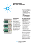
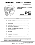
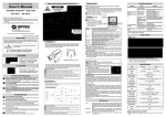
Migrate to the new Agilent MXG X-Series
signal generator and generate true performance
The new MXG exceeds the ESG’s performance in every category - output power, phase noise, spurious, and
low frequency coverage to 9 kHz. Enjoy frequency and amplitude switching speeds that are 10 to 20 times faster,
all in a compact, 3.5 inch (89 mm) tall unit. For more information visit www.agilent.com/find/X-Series_SG
Agilent
E4428C ESG
Analog Signal Generator
Data sheet
All specifications apply over a 0 to 55 °C range (unless otherwise
stated) and apply after a 45 minute warm-up time. Supplemental
characteristics, denoted as typical, nominal, or measured, provide
additional (non-warranted) information at 25 °C, which may be
useful in the application of the product.
Definitions
Specifications: Represents warranted performance.
Typical: Represents characteristic performance which is non-warranted. Describes
performance that will be met by a minimum of 80% of all products. All typical values
are indicated by parenthesis.
Nominal: Represents characteristic performance which is non-warranted. Represents
the value of a parameter that is most likely to occur; the expected mean or average.
Measured: Represents characteristic performance which is non-warranted. Represents the value of a parameter measured on an instrument during design stage.
Table of Contents
Key Features . . . . . . . . . . . . . . . . . . . . . . . . . . . . . . . . . . . . . . . . . . . . . . . . . . . . . . . . . . . . . . 3
Specifications for Frequency and Power . . . . . . . . . . . . . . . . . . . . . . . . . . . . . . . . . . . . . . . 4
Frequency . . . . . . . . . . . . . . . . . . . . . . . . . . . . . . . . . . . . . . . . . . . . . . . . . . . . . . . . . . . . 4
Sweep modes . . . . . . . . . . . . . . . . . . . . . . . . . . . . . . . . . . . . . . . . . . . . . . . . . . . . . . . . 4
Internal reference oscillator . . . . . . . . . . . . . . . . . . . . . . . . . . . . . . . . . . . . . . . . . . . . . 4
Output power . . . . . . . . . . . . . . . . . . . . . . . . . . . . . . . . . . . . . . . . . . . . . . . . . . . . . . . . . 5
Spectral purity . . . . . . . . . . . . . . . . . . . . . . . . . . . . . . . . . . . . . . . . . . . . . . . . . . . . . . . . 9
Specifications for Analog Modulation . . . . . . . . . . . . . . . . . . . . . . . . . . . . . . . . . . . . . . . . 11
Frequency bands . . . . . . . . . . . . . . . . . . . . . . . . . . . . . . . . . . . . . . . . . . . . . . . . . . . . . 11
Frequency modulation . . . . . . . . . . . . . . . . . . . . . . . . . . . . . . . . . . . . . . . . . . . . . . . . . 11
Phase modulation . . . . . . . . . . . . . . . . . . . . . . . . . . . . . . . . . . . . . . . . . . . . . . . . . . . . 12
Amplitude modulation . . . . . . . . . . . . . . . . . . . . . . . . . . . . . . . . . . . . . . . . . . . . . . . . . 13
Wideband AM . . . . . . . . . . . . . . . . . . . . . . . . . . . . . . . . . . . . . . . . . . . . . . . . . . . . . . . 14
Pulse modulation . . . . . . . . . . . . . . . . . . . . . . . . . . . . . . . . . . . . . . . . . . . . . . . . . . . . . 14
Internal analog modulation source . . . . . . . . . . . . . . . . . . . . . . . . . . . . . . . . . . . . . . 15
External modulation inputs . . . . . . . . . . . . . . . . . . . . . . . . . . . . . . . . . . . . . . . . . . . . . 15
Composite modulation . . . . . . . . . . . . . . . . . . . . . . . . . . . . . . . . . . . . . . . . . . . . . . . . 16
Simultaneous modulation . . . . . . . . . . . . . . . . . . . . . . . . . . . . . . . . . . . . . . . . . . . . . . 16
General Characteristics . . . . . . . . . . . . . . . . . . . . . . . . . . . . . . . . . . . . . . . . . . . . . . . . . . . . 17
Operating characteristics . . . . . . . . . . . . . . . . . . . . . . . . . . . . . . . . . . . . . . . . . . . . . . 17
Accessories . . . . . . . . . . . . . . . . . . . . . . . . . . . . . . . . . . . . . . . . . . . . . . . . . . . . . . . . . 18
Inputs and outputs . . . . . . . . . . . . . . . . . . . . . . . . . . . . . . . . . . . . . . . . . . . . . . . . . . . 18
Ordering Information . . . . . . . . . . . . . . . . . . . . . . . . . . . . . . . . . . . . . . . . . . . . . . . . . . . . . . 21
Related Literature . . . . . . . . . . . . . . . . . . . . . . . . . . . . . . . . . . . . . . . . . . . . . . . . . . . . . . . . . 22
2
Key Features
Key standard features
Optional performance
• Industry-leading spectral purity
• Superior level accuracy
• High output power
• High-stability timebase
• Wideband FM and ΦM
• Excellent modulation accuracy and stability
• Step and list sweep, both frequency and power
• Built-in function generator
• Lightweight, rack-mountable
• 2-year calibration cycle
• Option 503, frequency range from 250 kHz to 3 GHz (electronic attenuator standard)
• Option 506, frequency range from 250 kHz to 6 GHz (mechanical attenuator only)
• Option UNB, higher output with mechanical attenuator
Note: Option 506 is standard with the high power mechanical attenuator used in
Option UNB, and therefore, both options cannot be ordered together.
• Option 1EM, move all front panel connectors to rear panel
3
Specifications for Frequency and Power
Frequency
Frequency range
Option
503 506
250 kHz to 3 GHz [electronic attenuator standard]
250 kHz to 6 GHz [mechanical attenuator only]
Frequency minimum 100 kHz1
Frequency resolution 0.01 Hz
Frequency switching speed Option 503
Freq.2 Freq./Amp.3
(< 9 ms) (< 9 ms)
[For hops < 5 MHz within a band]
(< 9 ms) (< 9 ms)
Phase offset Sweep modes
Option 506
Freq.2Freq./Amp.3
(< 16 ms) (< 17 ms)
(< 12 ms) (< 14 ms)
Phase is adjustable remotely [LAN, GPIB, RS-232] or via front panel
in nominal 0.1 ° increments
Operating modes Frequency step, amplitude step and arbitrary list
Dwell time 1 ms to 60 s
Number of points 2 to 65,535 (Step)
2 to 1601 (List)
Internal reference oscillator
Stability
Aging rate
< ±0.1 ppm/yr or
< ±0.0005 ppm/day after 45 days
Temp [0 to 55 °C] (< ±0.05 ppm)
Line voltage (< ±0.002 ppm)
Line voltage range
(+5% to –10%)
RF reference input requirements
Frequency 1, 2, 5, 10 MHz ±0.2 ppm
RF reference output
Frequency Amplitude
1. Performance below 250 kHz not guaranteed.
2. To within 0.1 ppm of final frequency above 250 MHz or within 100 Hz below 250 MHz.
3. Frequency switching time with the amplitude settled within ±0.1 dB.
4
10 MHz
4 dBm ±2 dB
Specifications for Frequency and Power
PowerOption UNB
Option 503
Option 503
250 kHz to 250 MHz +11 to –136 dBm +15 to –136 dBm
> 250 MHz to 1 GHz +13 to –136 dBm +17 to –136 dBm
> 1 to 3 GHz
+10 to –136 dBm +16 to –136 dBm
> 3 to 6 GHz
N/A
N/A
Option 506
+12 to –136 dBm
+14 to –136 dBm
+13 to –136 dBm
+10 to –136 dBm
Maximum available power (measured)
26
24
Option UNB
22
Power [dB]
Output power
Option 506
20
18
16
14
Option 503
12
10
0
1000
2000
3000
4000
5000
6000
Frequency [MHz]
Level resolution 0.02 dB
Level range with Attenuator Hold active
Option 503
250 kHz to 1 GHz 23 dB > 1 to 3 GHz 20 dB > 3 to 6 GHz
N/A
Option UNB
Option 503
27 dB
26 dB
N/A
Option 506
24 dB
23 dB
20 dB
5
Specifications for Frequency and Power
Level accuracy [dB]
Option 503 1
+7 to –50 dBm
250 kHz to 2.0 GHz ±0.5
2.0 to 3 GHz ±0.6
Power level
–50 to –110 to
–110 dBm
–127 dBm
±0.5
±0.7
±0.6
±0.8
Option UNB 2
+10 to –50 dBm
250 kHz to 2.0 GHz ±0.5
2.0 to 3 GHz ±0.6
Power level
–50 to –110 to
–110 dBm
–127 dBm
±0.7
±0.8
±0.8
±1.0
Option 506 3
+7 to –50 dBm
250 kHz to 2.0 GHz ±0.6
2.0 to 3 GHz ±0.6
3 to 4 GHz ±0.8
4 to 6 GHz
±0.8
Power level
–50 to –110 to
–110 dBm
–127 dBm
±0.8
±0.8
±0.8
±1.0
±0.9
±1.5
±0.9
(±1.5)
Option 503 Levelat
Accuracy
at -110
dBm (Measured)
Option 503 level accuracy
–110
dBm
(measured)
1
0.8
0.8
0.6
0.6
0.4
0.4
0.2
0.2
0
–0.2
–0.4
–0.4
–0.6
–0.6
–0.8
–0.8
0
500
1000
1500
2000
2500
3000
–1
0
1000
2000
3000
Frequency (MHz)
(±1.5)
(±2.5)
< –127 dBm
(±1.5)
(±2.5)
(±2.5)
5000
6000
7000
Note: Special Option HF8 is required
for frequency capability up to 7 GHz
(±0.15 dB) [relative to ALC on]
After power search is executed.
Level switching speed Option 503
Normal operation [ALC on]
(< 15 ms)
When using power search manual (< 83 ms)
When using power search auto
(< 103 ms)
6
< –127 dBm
4000
Frequency (MHz)
Level accuracy with ALC off
Conditions: 1.
2.
3.
(±1.5)
(±2.5)
0
–0.2
–1
< –127 dBm
Option 506 Level
dBm (Measured)
Option 506 level accuracy
atAccuracy
–110at –110
dBm
(measured)
1
Error (dB)
Error (dB)
Option UNB
Option 503
(< 21 ms)
(< 95 ms)
(< 119 ms)
Option 506
(< 21 ms)
(< 95 ms)
(< 119 ms)
Quoted specifications for 23 °C ±5 °C. Accuracy degrades by less than 0.03 dB/°C over full temperature range. Accuracy degrades by 0.3 dB above +7 dBm,
and by 0.8 dB above +10 dBm.
Quoted specifications for 23 °C ±5 °C. Accuracy degrades by less than 0.03 dB/°C over full temperature range. Accuracy degrades by 0.2 dB above +10 dBm,
and by 0.8 dB above +13 dBm.
Quoted specifications for 23 °C ±5 °C. Accuracy degrades by less than 0.02 dB/°C over full temperature range. Accuracy degrades by 0.2 dB above +7 dBm.
Specifications for Frequency and Power
Repeatability and linearity
Repeatability
1900 MHz CW, 5 dBm, attenuator hold On, ALC On
0.1
0.5
0.09
0.45
Typical unit
Limits
0.08
0.4
0.07
0.35
0.06
0.3
Power error (dB)
Powererror (dB)
Repeatability
1900 MHz CW, 5 dBm, attenuator hold Off, ALC Off
0.05
0.04
0.25
0.2
0.03
0.15
0.02
0.10
0.01
0.05
0
0
20
40
Typical unit
Limits
0
60
100
80
1
0
120
2
3
Elapsed time (minutes)
4
5
6
7
8
9
10
Elapsed time (minutes)
Repeatability measures the ability of the instrument to return to a given power setting after a
random excursion to any other frequency and power setting. It is a relative measurement that
reflects the difference in dB between the maximum and minimum power readings for a given
setting over a specific time interval. It should not be confused with absolute power accuracy,
which is measured in dBm.1
Relative level accuracy
Initial power 7 dBm
0.4
Lower limit
Lower STD deviation
Mean
Upper STD deviation
Upper limit
0.3
0.2
Power error (dB)
0.1
0
-0.1
-0.2
-0.3
-0.4
0
-20
-40
-60
-80
-100
-120
-140
Final power (dBm)
Relative level accuracy measures the accuracy of a step change from any power level to any
other power level. This is useful for large changes (i.e. 5 dB steps).1
1. Repeatability and relative level accuracy are typical for all frequency ranges.
7
Specifications for Frequency and Power
Linearity
CW, 850 MHz, attenuator hold On, ALC On
0.3
Typical Option 503 unit
Typical Option UNB unit
Typical Option 506 unit
0.25
0.2
0.15
Lower limit
Upper limit
0.1
ALC offset error (dB)
Linearity measures the accuracy of small changes while the attenuator
is held in a steady state (to avoid power glitches). This is useful for
fine resolution changes.1
0.05
0
-0.05
-0.1
-0.15
-0.2
-0.25
Limit is undefined above 13 dBm
for Option 503 units. Limit line applies
only to UNB and 506 units.
-0.3
-0.35
-0.4
-10
-8
-6
-4
-2
0
2
4
6
8
10
12
14
16
Amplitude (dBm)
Linearity
CW, 1900 MHz, attenuator hold On, ALC On
Linearity
CW 5750 MHz, attenuator hold On, ALC On
0.3
0.3
0.25
Typical Option 503 unit
Typical Option UNB unit
Typical Option 506 unit
Lower limit
Upper limit
0.2
0.1
0.2
0.15
ALC offset error (dB)
ALC offset error (dB)
0.15
0.05
0
-0.05
-0.1
-0.15
0.1
0.05
0
-0.05
-0.1
-0.15
-0.2
-0.2
-0.25
-0.25
-0.3
-0.3
-10
-8
-6
-4
-2
0
2
4
6
8
10
12
14
Amplitude (dBm)
1. Repeatability and relative level accuracy are typical for all frequency ranges.
8
Lower limit
Upper limit
Mean, Option 506 unit
Lower Option 503 deviation
Upper Option 503 deviation
0.25
16
-10
-8
-6
-4
-2
0
2
amplitude (dBm)
4
6
8
10
Specifications for Frequency and Power
Spectral purity
SSB Phase noise [at 20 kHz offset]
at 500 MHz
< –135 dBc/Hz, (< –138 dBc/Hz)
at 1 GHz
< –130 dBc/Hz, (< –134 dBc/Hz)
at 2 GHz
< –124 dBc/Hz, (< –128 dBc/Hz)
at 3 GHz
< –121 dBc/Hz, (< –125 dBc/Hz)
at 4 GHz
< –118 dBc/Hz, (< –122 dBc/Hz)
at 6 GHz
< –113 dBc/Hz, (< –117 dBc/Hz)
Residual FM [CW mode, 0.3 to 3 kHz BW, CCITT, rms]
< N x 1 Hz (< N x 0.5 Hz)1
Harmonics2 [output level ≤ +4 dBm Option 503, ≤ +7.5 dBm Option UNB,
≤ +4.5 dBm Option 506] < –30 dBc above 1 GHz,
(< –30 dBc 1 GHz and below)
Nonharmonics3 [≤ +7 dBm output level decreases, ≤ +4 dBm Option 506] 4
1.
2.
3.
4.
5.
6.
250 kHz to 250 MHz 250 MHz to 500 MHz
500 MHz to 1 GHz
1 to 2 GHz
2 to 4 GHz
4 to 6 GHz
> 3 kHz
offset
< –65 dBc
< –80 dBc
< –80 dBc
< –74 dBc
< –68 dBc
< –62 dBc
Subharmonics
≤ 1 GHz > 1 GHz None
None
> 10kHz
offset
(< –58 dBc)
< –80 dBc
< –80 dBc
< –74 dBc
< –68 dBc
< –62 dBc
Jitter in µUI 5,6
Carrier
frequency
155 MHz
622 MHz
2.488 GHz
SONET/SDH
data rates
155 MB/s
622 MB/s
2488 MB/s
rms jitter
bandwidth
100 Hz to 1.5 MHz
1 kHz to 5 MHz
5 kHz to 15 MHz
Jitter in seconds
Carrier
frequency
155 MHz
622 MHz
2.488 GHz
SONET/SDH
data rates
155 MB/s
622 MB/s
2488 MB/s
rms jitter
bandwidth
100 Hz to 1.5 MHz
1 kHz to 5 MHz
5 kHz to 15 MHz
(µUI rms)
(78)
(46)
(74)
(0.6 ps)
(74 fs)
(30 fs)
Refer to frequency bands on page 11 for N values.
Harmonic performance outside the operating range of the instrument is typical.
Spurs outside the operating range of the instrument are not specified.
Specifications apply for CW mode only.
Calculated from phase noise performance in CW mode only at -2.5 dBm for Option 503 instruments, -0.5 dBm with Option 506, and +2.5 dBm with Option UNB.
For other frequencies, data rates, or bandwidths, wplease contact your sales representative.
9
Specifications for Frequency and Power
Characteristic SSB phase noise (measured)
CW mode
CW mode

fc = 850 MHz
fc = 5.7 GHz [Option 506]
PN mode 1
PN mode 2
CW mode
fc = 1900 MHz
Phase noise modes 1 and 2 at fc = 900 MHz
–60
–70
–80
–90
–100
–110
–120
–130
–140
–150
–160
10
100
1K
10K
100K
1M
10M
L(f) (dBc/Hz) vs. f (Hz)
fc = 1000 MHz
CW mode
fc = 2200 MHz
10
Specifications for Analog Modulation
Frequency bands
Frequency modulation1
Band 1
2
3
4
5
6
Frequency range
N number
250 kHz to ≤ 250 MHz
1
> 250 MHz to ≤ 500 MHz
0.5
> 500 MHz to ≤ 1GHz
1
> 1 to ≤ 2 GHz
2
> 2 to ≤ 4 GHz
4
> 4 to ≤ 6 GHz
8
Maximum deviation 2
Resolution N x 1 MHz
0.1% of deviation or 1 Hz,
whichever is greater
Modulation frequency rate [deviation = 100 kHz]
Coupling
1 dB bandwidth
3 dB bandwidth
(DC to 10 MHz)
(DC to 0.9 MHz)
(5 Hz to 10 MHz)
(5 Hz to 0.9 MHz) FM path 1[DC]
FM path 2 [DC]
FM path 1 [AC]
FM path 2 [AC]
DC to 100 kHz
DC to 100 kHz
20 Hz to 100 kHz
20 Hz to 100 kHz
Deviation accuracy2 [1 kHz rate, deviation < N x 100 kHz]
< ± 3.5% of FM deviation + 20 Hz
Carrier frequency accuracy relative to CW in DCFM2,3 ±0.1% of set deviation + (N x 1 Hz)
Distortion2 [1 kHz rate, dev.= N x 100 kHz]
< 1%
FM using external inputs 1 or 2
Sensitivity
1 Vpeak for indicated deviation
Input impedance
50 Ω, nominal
FM path 1 and FM path 2 are summed internally for composite modulation.
The FM 2 path is limited to a maximum rate of 1 MHz. The FM 2 path must be
set to a deviation less than FM 1 path.
1. All analog performance above 3 GHz is typical.
2. Refer to frequency bands on this page to compute specifications.
3. At the calibrated deviation and carrier frequency, within 5 °C of ambient temperature at time of calibration.
11
Specifications for Analog Modulations
Phase modulation1
Resolution 0.1% of set deviation
Modulation frequency response2
Mode Normal BW
High BW
Maximum
deviation
N x 10 radians
N x 1 radians
Allowable rates [3 dB BW]
ØM path 1
ØM path 2
DC to 100 kHz
DC to 100 kHz
(DC to 1 MHz)
(DC to 0.9 MHz)
Deviation accuracy [1 kHz rate, Normal BW mode] < ±5% of deviation + 0.01 radians
Distortion 2 [1 kHz rate, deviation, < 10N radians, Normal BW mode]
< 1%
ØM using external inputs 1 or 2
Sensitivity
1 Vpeak for indicated deviation
50 Ω, nominal
Input impedance
Paths 1. All analog performance above 3 GHz is typical.
2. Refer to frequency bands on page 11 for N.
3. Bandwidth is automatically selected based on deviation.
12
ØM path 1 and ØM path 2 are summed internally for composite
modulation. The ØM 2 path is limited to a maximum rate of
1 MHz. ØM path 2 must be set to a deviation less than the
ØM path 1.
Specifications for Analog Modulations
Amplitude modulation1, 2
[fc > 500 kHz]
Range
0 to 100%
Resolution 0.1%
Rates [3 dB bandwidth]
DC coupled
0 to 10 kHz
AC coupled
10 Hz to 10 kHz
Accuracy 2,3 1 kHz rate
< ±(6% of setting +1%)
Distortion2,3 [1 kHz rate, THD]
Option 503
30% AM
< 1.5%
90% AM
(< 4%)
Option 506
< 1.5%
(< 5%)
AM using external inputs 1 or 2
Sensitivity
1 Vpeak to achieve indicated depth
50 Ω, nominal
Input impedance
Paths AM path 1 and AM path 2 are summed internally for
composite modulation.
1. All analog performance above 3 GHz is typical.
2. AM is typical above 3 GHz.
3. Peak envelope power of AM must be 3 dB less than maximum output power below 250 MHz.
13
Specifications for Analog Modulation
Pulse modulation
On/off ratio
≤ 4 GHz
> 4 GHz
> 80 dB
(> 64 dB)
Rise/fall times
(150 ns)
Minimum width
ALC on
ALC off
(2 µs)
(0.4 µs)
Pulse repetition frequency
ALC on
(10 Hz to 250 kHz)
ALC off
(DC to 1.0 MHz)
Level accuracy1 [relative to CW at ≤ 4 dBm Option 503, ≤ 7.5 dBm Option UNB,
≤ 4.5 dBm Option 506]
(< ±1 dB)
Pulse modulation using external inputs
Input voltage
RF on
> +0.5 V, nominal
RF off
< +0.5 V, nominal
Input impedance 50 Ω, nominal
Internal pulse generator
Square wave rate 0.1 Hz to 20 kHz
Pulse
Period
8 µs to 30 seconds
Width
4 µs to 30 seconds
Resolution
2 µs
1. With ALC off, specifications apply after the execution of power search. With ALC on, specifications apply for pulse repetition rates ≤ 10 kHz and pulse widths ≥ 5 µs.
14
Specifications for Analog Modulation
Internal analog modulation source
[Provides FM, AM, pulse, and phase
modulation signals and LF audio out]
Waveforms
sine, square, ramp, triangle, pulse, noise
Rate range
Sine
Square, ramp, triangle 0.1 Hz to 100 kHz
0.1 Hz to 20 kHz
Resolution
0.1 Hz
Frequency accuracy
same as RF reference source
Swept sine mode [frequency, phase continuous]
Operating modes
Triggered or continuous sweeps
Frequency range
0.1 Hz to 100 kHz
Sweep time
1 ms to 65 sec
Resolution
1 ms
Dual sinewave mode
Frequency range
0.1 Hz to 100 kHz
Amplitude ratio 0 to 100%
Amplitude ratio resolution 0.1%
LF audio out mode
Amplitude
0 to 2.5 Vpeak into 50 Ω
50 Ω nominal
Output impedance
Noise
Noise with adjustable amplitude generated as a peak-to-peak value
(RMS value is approximately 80% of displayed value)
External modulation inputs
Modulation types
Ext 1 Ext 2 FM, ØM, AM, pulse
FM, ØM, AM, and pulse
High/Low Indicator [100 Hz to 10 MHz BW, AC coupled inputs only]. Activated when
input level error exceeds 3% [nominal].
15
Specifications for Analog Modulation
Composite modulation
Simultaneous modulation
16
AM, FM, and ØM each consist of two modulation paths which are summed internally
for composite modulation. The modulation sources may be any two of the following:
Internal, External 1, External 2.
Multiple modulation types may be simultaneously enabled. For example, AM, and FM
can run concurrently and all will affect the output RF. This is useful for simulating signal
impairments. There are some exceptions: FM and ØM cannot be combined. Two
modulation types cannot be generated simultaneously by the same modulation source.
General Characteristics
Operating characteristics
Power requirements
90 to 254 V; 50 or 60 Hz; 300 W maximum,
power factor corrected. Not for 400 Hz use.1
Operating temperature range2 0 to 55 °C
Storage temperature range –40 to 70 °C
Shock and vibration Meets MIL-STD-28800E Type III, Class 3.
Leakage Conducted and radiated emissions conform
to CISPR 11.
Leakage is typically < 1 µV [nominally 0.1 µV with a
2-turn loop] at ≤ 1000 MHz, measured with a
resonant dipole antenna, one inch from any surface
with output level < 0 dBm [all inputs/outputs
properly terminated].
Storage registers Memory is shared by instrument states, user data files,
sweep list files and waveform sequences. Depending on
the number and size of these files, up to 100 storage
registers and 1000 register sequences [10 per register] are available.
Weight < 16 kg [35 lb.] net, < 23 kg [50 lb.] shipping
Dimensions 133 mm H x 426 mm W x 432 mm D
[5.25 in H x 16.8 in W x 17 in D]
Remote programming
Interface Control languages3 Functions controlled GPIB [IEEE-488.2-1987] with listen and talk, RS-232, LAN [10BaseT].
SCPI version 1996.0, also compatible with 8662A,
8663A, 8656B and 8657A/B/C/D/J1 mnemonics.
All front panel functions except power switch and knob.
ISO compliant
The E4428C ESG is manufactured in an ISO-9001
registered facility in concurrence with
Agilent Technologies commitment to quality.
Reverse power protection
250 kHz to 2 GHz > 2 to 4 GHz > 4 to 6 GHz
Max DC voltage Option 503
47 dBm
44 dBm
N/A
40 V
Option 506
30 dBm
30 dBm
30 dBm
SWR
250 kHz to 2.2 GHz > 2.2 GHz to 3 GHz > 3 GHz to 4 GHz
> 4 GHz to 6 GHz
Option 503
(< 1.5:1) (< 1.4:1) (< 1.5:1)
N/A
Option UNB
(< 1.5:1)
(< 1.5:1)
(< 1.7:1)
N/A
Output impedance 50 Ω nominal
Option 506
(< 1.6:1)
(< 1.4:1)
(< 1.7:1)
(< 1.8:1) 1. For 400 Hz systems, order transformer 70001-60066.
2. Save and recall of user files and instrument states from non-volatile storage is guaranteed only over the range 0 to 40 °C.
3. ESG series does not implement 8657A/B “Standby” or “On” [R0 or R1, respectively] mnemonics.
17
General Characteristics
Accessories
Inputs and outputs
All front panel connectors can be moved
to rear with Option 1EM.
Transit case 10 MHz input
10 MHz output
Part number 9211-1296
Accepts a 1, 2, 5, or 10 MHz ±0.2 ppm. Nominal input
level –3.5 to +20 dBm, impedance 50 ohms.
[BNC, rear panel]
Outputs the 10 MHz reference signal. Level nominally
+3.9 dBm ±2 dB. Nominal output impedance 50 ohms.
[BNC, rear panel]
External 1 input
This BNC input connector accepts a ±1 Vpeak signal for
AM, FM, pulse, and phase modulation. For all these
modulations, ±1 Vpeak produces the indicated deviation or
depth. When ac-coupled inputs are selected for AM, FM,
or phase modulation and the peak input voltage differs
from 1 Vpeak by more than 3%, the hi/lo annunciator light
on the display. The input impedance is 50 ohms and the
damage levels are 5 Vrms and 10 Vpeak.. If you configure your
signal generator with Option 1EM, this input is relocated
to a female BNC connector on the rear panel.
External 2 input
This BNC input connector accepts a ±1 Vpeak signal for
AM, FM, phase modulation, and pulse modulation. With
AM, FM, or phase modulation, ±1 Vpeak produces the
indicated deviation or depth. With pulse modulation,
+1 V is on and 0 V is off. When ac-coupled inputs are
selected for AM, FM, or phase modulation, and the peak
voltage differs from 1 Vpeak by more than 3%, the hi/lo
annunciator light on the display. The input impedance is
50 ohms and the damage levels are 5 Vrms and 10 Vpeak
If you configure your signal generator with Option 1EM,
this input is relocated to a female BNC connector on the
rear panel.
GPIB Allows communication with compatible devices.
[rear panel]
LF output Outputs the internally-generated LF source. Outputs 0 to
2.5 Vpeak into 50 ohms, or 0 to 5 Vpeak into high impedance.
[BNC, front panel]
RF output
Nominal output impedance 50 ohms.
[type-N female, front panel]
Sweep output
Trigger input
Trigger output
Generates output voltage, 0 to +10 V when signal
generator is sweeping. Output impedance < 1 ohm, can
drive 2000 ohms. [BNC, rear panel]
Accepts CMOS1 signal for triggering point-to-point in
manual sweep mode, or to trigger start of LF sweep.
The damage levels are –0.5 to +5.5 V. [BNC, rear panel]
Outputs a TTL signal: high at start of dwell, or when
waiting for point trigger in manual sweep mode; low
when dwell is over or point trigger is received, high or
low 2 μs pulse at start of LF sweep. [BNC, rear panel]
1. Rear panel inputs and outputs are 3.3 V CMOS, unless indicated otherwise. CMOS inputs will accept 5 V CMOS, 3 V CMOS, or TTL voltage levels.
18
General Characteristics
LAN connector
LAN communication is supported by the signal generator via the LAN connector. It is
functionally equivalent to the GPIB connector. The LAN connector enables the signal
generator to be remotely programmed by a LAN-connected computer. The distance
between a computer and the signal generator is limited to 100 meters [10BaseT].
For more information about the LAN, refer to the Getting Started chapter in the
Programming Guide.
Data transfer speeds
LAN [FTP]
file transfer to volatile memory
to hard drive
LAN [SCPI]
command transfer to volatile memory
to hard drive
Internal file transfer from hard drive to volatile memory
(700 KB/sec)
(500 KB/sec)
(146 KB/sec)
(128 KB/sec)
(1280 KB/sec)
RS-232 connector
This male DB-9 connector is an RS-232 serial port that can be used for controlling
the signal generator remotely. It is functionally equivalent to the GPIB connector. The
following table shows the description of the pinouts. The pin configuration is shown
below.
Pin number
1
2
3
4
5
6
7
8
9
5
Signal description
No connection
Receive data
Transmit data
+5 V
Ground, 0 V
No connection
Request to send
Clear to send
No connection
4
9
3
8
2
7
Signal name
RECV
XMIT
RTS
CTS
1
6
View looking into rear panel connector
19
Ordering Information
1
Frequency options
Performance enhancement options
• E4428C-503
• E4428C-506
250 kHz to 3 GHz frequency range [electronic attenuator standard]
250 kHz to 6 GHz frequency range [mechanical attenuator only]
• E4428C-UNB
High output power with mechanical attenuator
Note: Option 506 is standard with the high power mechanical attenuator used in
Option UNB, and therefore, both options cannot be ordered together.
• E4428C-1EM
Moves all front panel connectors to rear
Manual and accessories
• E4428C-1CM • E4428C-1CP • E4428C-1CN • E4428C-CD1 • E4428C-ABA • E4428C-0BW • E4428C-UK6 Warranty and calibration plans
For more information, please visit: www.agilent.com/find/removealldoubt.
Rack mount kit without handles
Rack mount kit with handles
Front handle kit
CD-ROM of English user guide and assembly level service manual
(standard with instrument)
Printed English documentation set
Service documentation, assembly level
Commercial calibrations certificate with test data
• Extended return-to-Agilent warranty and service
• Agilent calibration upfront plan
• Agilent calibration plus upfront plan
• Z540 calibration upfront plan
1. All options should be ordered using E4428C-xxx, where the xxx represents the option number.
20
Related Literature
• Signal Generator Spectral Purity Considerations in RF Communications
Testing, Application Note 388, Literature Number 5952-2019.
•RF Source Basics, a self-paced tutorial (CD-ROM),
Literature Number 5980-2060E.
•IntuiLink Software, Data Sheet, Literature Number 5980-3115EN.
•Security of Agilent Signal Generators: Issues and Solutions,
Application Note, Literature Number 5989-1091EN.
21
www.agilent.com
Additional Resources
See the ESG Web page
Get the latest news, product and
support information, application
literature, firmware upgrades and
more. Agilent’s Internet address
for the ESG is:
www.agilent.com/find/esg
For more information on Agilent
Technologies’ products, applications or
services, please contact your local Agilent
office. The complete list is available at:
Agilent Advantage Services is committed
to your success throughout your equipment’s lifetime. To keep you competitive,
we continually invest in tools and
processes that speed up calibration and
repair and reduce your cost of ownership.
You can also use Infoline Web Services
to manage equipment and services more
effectively. By sharing our measurement
and service expertise, we help you create
the products that change our world.
www.agilent.com/find/advantageservices
www.agilent.com/quality
Agilent Email Updates
www.agilent.com/find/emailupdates
Get the latest information on the
products and applications you select.
www.agilent.com/find/contactus
Americas
Canada
Brazil Mexico
United States
Asia Pacific
Australia 1 800 629 485
China
800 810 0189
Hong Kong 800 938 693
India 1 800 112 929
Japan
0120 (421) 345
Korea
080 769 0800
Malaysia 1 800 888 848
Singapore 1 800 375 8100
Taiwan
0800 047 866
Other AP Countries (65) 375 8100
Europe & Middle East
Belgium 32 (0) 2 404 93 40
Denmark
45 45 80 12 15
Finland
358 (0) 10 855 2100
France
0825 010 700*
Agilent Channel Partners
www.agilent.com/find/channelpartners
Get the best of both worlds: Agilent’s
measurement expertise and product
breadth, combined with channel
partner convenience.
(877) 894 4414
(11) 4197 3600
01800 5064 800
(800) 829 4444
*0.125 €/minute
Germany
49 (0) 7031 464 6333
Ireland
1890 924 204
Israel972-3-9288-504/544
Italy
39 02 92 60 8484
Netherlands
31 (0) 20 547 2111
Spain
34 (91) 631 3300
Sweden
0200-88 22 55
United Kingdom 44 (0) 118 927 6201
For other unlisted countries:
www.agilent.com/find/contactus
Revised: January 6, 2012
Product specifications and descriptions
in this document subject to change
without notice.
© Agilent Technologies, Inc. 2012
Published in USA, May 21, 2012
5989-1992EN