1
t
English
SHIMANO NEXUS 8-SPEED HUB
SG-8R20
SERVICE MANUAL
vol.2
Contents
Disassembly of the Inter-8 hub • • • • • • • • • • • • • • • • • • • • • • • • • • • • • • • • • • • • • • 3
Assembly of the Inter-8 hub • • • • • • • • • • • • • • • • • • • • • • • • • • • • • • • • • • • • • • • • • 10
Cassette Joint & Mesurement Tool • • • • • • • • • • • • • • • • • • • • • • • • • • • • • • • • • • 17
Spare parts list (SG-8R20 / BR-IM70-R / C J-8S20) • • • • • • • • • • • • • • • • • • • • • • 18
Spare parts list (SB-8S20) • • • • • • • • • • • • • • • • • • • • • • • • • • • • • • • • • • • • • • • • • • • • 19
Spare parts list (CJ-8S40) • • • • • • • • • • • • • • • • • • • • • • • • • • • • • • • • • • • • • • • • • • • • 20
Spare parts list (BL-IM60) • • • • • • • • • • • • • • • • • • • • • • • • • • • • • • • • • • • • • • • • • • • • 21
Spare parts list (ST-8S20) • • • • • • • • • • • • • • • • • • • • • • • • • • • • • • • • • • • • • • • • • • • • 22
Spare parts list (BL-IM65) • • • • • • • • • • • • • • • • • • • • • • • • • • • • • • • • • • • • • • • • • • • • 23
2
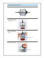
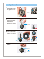
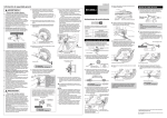
Disassembly of the Inter-8 hub
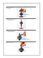
1.
Hold the two bevelled surfaces
of the hub axle on the sprocket side in a vice.
2.
Remove the lock nut for left
hand cone with 14 X14mm
spanners.
Lock nut for left hand cone
(Y-31Z 06020)
3.
Remove the left hand cone.
Left hand cone
(Y-308 98070)
3
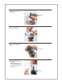
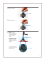
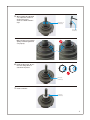
4.
Remove the ball retainer P
(3/16"X13).
Ball retainer P
(Y-34R 98070)
5.
Remove the hub shell.
6.
Remove the right hand dust
cap.
Right hand dust cap
(Y-34R 98110)
7.
Remove the stop ring with
screwdriver.
At this time, the stop ring
come off with great force. Be
careful of the safety using
cloth and so on.
Stop ring
(Y-34R 79000)
4
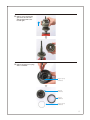
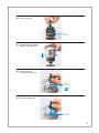
8.
Remove carrier unit and ring
gear unit at the same time
without tuning them to the
left and right.
9.
Remove the ring gear stop ring
with a screwdriver.
Ring gear stop ring
(Y-34R 80000)
Carrier unit
(Y-34R 98020)
Ring gear 1
(Y-34R 47000)
Ring gear stop ring
(Y-34R 80000)
5
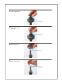
10.
Remove ball retainer O
(3/16"X26).
Ball retainer O
(Y-34R 98030)
11.
Then hold the axle unit upside down in a vice.
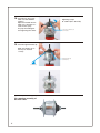
12.
Remove the right hand lock
nut with 17mm spanner.
Right hand lock nut
(Y-33Z 07020)
13.
Remove stop washer.
Stop washer
(Y-34R 09000)
6
14.
Remove lock washer.
Lock washer
(Y-34R 98090)
15.
Remove driver plate.
Driver plate
(Y-34R 12000)
16.
Support the driver by
the vice.
Set the tool and hit it with
hammer untill right hand
cone and axle unit is
separate.
If you try to disassemble
the right hand cone without
using this tool, the return
spring in the axle unit may
disengage.
Set the tool into the groove
so that the pawl A is on the
surface of the tool.
Tool TL-8S10
(Y-70800100)
A
7
17.
Remove right hand cone.
Right hand cone
(Y-34R 98080)
18.
Remove ball retainer P
(3/16"X13).
Ball retainer P
(Y-34R 98070)
19.
Remove driver unit.
Driver unit
(Y-34R 98060)
20.
Remove return spring.
Return spring
(Y-34R 21000)
8
21.
Remove the clutch unit while
turning it counterclockwise
and fixing two pawls to two
grooves as shown in the picture.
Clutch unit
(Y-34R 98050)
9
Assembly of the Inter-8 hub
1.
When installing the clutch unit,
align two pawls of the clutch
unit with two grooves. After
installing the clutch unit, turn
it clockwise.
Clutch unit
(Y-34R 98050)
2.
3.
Install the return spring while
aligning it with the blue line
shown in the picture.
Be careful not to install it
upside-down.
(The bigger part is downside.)
Return spring
(Y-34R 21000)
Set the drive unit while align
the shallow side of groove of
driver unit and wider portion
of swelling on the clutch unit.
Set drive unit while turn it
counterclockwise.
4.
Install the ball retainer P
(3/16"X13).
Ball retainer P
(Y-34R 98070)
GREASE
(Y-041 20600)
10
5.
When installing the right hand
cone, adjust two serration as
shown in the picture.
Set the tool and hit it untill it
stops.
Right hand cone
(Y-34R 98080)
Tool TL-8S20
(Y-70800200)
Make sure that seal is installed
equally, and install right hand
cone properly.
seal
6.
Install the driver plate. Be careful of the setting direction
asshown in the picture.
Driver plate
(Y-34R 12000)
7.
Install lock washer.
Lock washer
(Y-34R 98090)
11
8.
When installing the stop
washer, align two pawls of the
stop washer with the grooves of
lock washer.
Stop washer
(Y-34R 09000)
9.
Install the right hand lock nut
(3.4mm) with 17mm spanner.
Take care that the stop washer
does not turn.
Tightening torque:
25 - 30 N·m {218 - 261 in.lbs}
Right hand lock nut
(Y-33Z 07020)
10.
Then hold the axle unit upside down in a vice.
11.
Install the ball retainer O
(3/16"X26) while pressing in
pawl on the driver & axle unit.
Ball retainer O
(Y-34R 98030)
GREASE
(Y-041 20600)
12
12.
How to install the carrier unit
and ring gear.
(Without any tools)
Align three marks of the
ring gear with three
grooves as shown in the
picture.
Carrier unit
(Y-34R 98020)
GREASE
(Y-041 20600)
Ring gear 1
(Y-34R 47000)
Tool TL-8S30
(Y-70800300)
(With tool)
Align the grooves of the
tool with the marks of the
ring gear.
GREASE
(Y-041 20600)
Install the ring gear stop
ring with a screwdriver.
Ring gear stop ring
(Y-34R 80000)
13
13.
Aligh the swelling of ring
gear/carrier unit and the
groove of axle unit.
After installing ring gear and
carrier unit, turn units firmly
and check that pawls are in
their position.
GREASE
(Y-041 20600)
To proceed this section, it is
important to set four pawls in
their position.
Use flat blade screwdriver to
push pawls as shown in the
instruction then install ring
gear and carrier unit slowlly.
pawls
No good
Pawls are not in their proper position
14
14.
Insert the stop ring.
Stop ring
(Y-34R 79000)
15.
Install the hub shell unit while
turning it counterclockwise.
16.
Insert ball retainer P
(3/16"X13) in the hub shell.
Ball retainer P
(Y-34R 98070)
GREASE
(Y-041 20600)
17.
Install the left hand cone.
Left hand cone
(Y-308 98070)
15
18.
19.
Install the lock nut for left
hand cone with 14X14mm
spanners.
Adjust the hub with the left
hand cone so that there is a
small amount of play.
This play should disappear
after tightening the locknut.
Tightening torque:
25 - 30 N·m {218 - 261 in.lbs}
Lock nut for left hand cone
(Y-31Z 06020)
Install the right hand dust cap.
Make sure that the seal of
dust cap also installed
correctly.
Right hand dust cap
(Y-34R 98110)
GREASE
(Y-041 20600)
This completes assembly of
the Inter-8 hub.
16
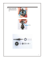
Cassette Joint
CJ-8S20 for 8 speed
CJ-NX10 for 7 speed
CJ-8S40 for 8 speed
CJ-7S40 for 7 speed
CJ-8S20
CJ-NX10
Mesurement Tool
101mm
TL-CJ10 for CJ-8S20
101mm
TL-CJ40 for CJ-8S20
124mm
TL-CJ40 for CJ-8S40
17
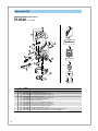
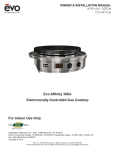
Spare parts list
SHIMANO NEXUS 8-SPEED HUB w/Hi-Power Roller Brake
22
20
26
MIN
JA
28 29 11
GREA
23
04
30
31
42
33
32
34
35
36
18 17
SE
24
SG-8R20 JAPAN VIA
TL-8S30
RELEA
SE
25
CJ-8S20
Internal Assembly
N
2
7L
PA
Grease
41
Inter-M Brake
1
2Nm
17 19
Inter-8 Hub
PE-LD
SG-8R20
BR-IM70-R
21
37
1
For w/o Roller Brake
(SG-8R20-VS)
2
3
4
5
6
7
27
8
9
10
38
TL-8S20
11 12 13 14 15 16
39
2
TL-8S10
40
Q'TY
ITEM
NO.
1
2
3
4
5
6
7
8
9
10
11
12
13
14
15
16
17
18
19
20
21
22
23
24
25
26
27
28
29
30
31
* 32
33
34
35
36
37
* 38
* 39
* 40
41
42
SHIMANO
CODE NO.
Y-34R 98010
Y-34R 79000
Y-34R 98020
Y-34R 47000
Y-34R 80000
Y-34R 98030
Y-34R 98040
Y-34R 98050
Y-34R 21000
Y-34R 98060
Y-34R 98070
Y-34R 98080
Y-34R 12000
Y-34R 98090
Y-34R 09000
Y-33Z 07020
Y-314 14010
Y-33Z 20500
Y-33M39600
Y-33M39700
Y-33M39510
Y-33M39610
Y-33M39710
Y-75V 13041
Y-75M98050
Y-33F 98090
Y-75M98060
Y-33F 98100
Y-75E 98010
Y-75F 11000
Y-75F 98020
Y-75E 98020
Y-75T 05000
Y-34R 98100
Y-31Z 06020
Y-308 98070
Y-34R 98110
Y-322 03220
Y-322 03420
Y-322 03520
Y-322 03620
Y-330 60000
Y-330 60100
Y-321 20100
Y-74Y 98120
Y-74Y 18000
Y-74Y 98130
Y-33Z 98020
Y-74Y 98030
Y-708 00300
Y-708 00200
Y-708 00100
Y-041 20600
Y-041 20400
Y-041 40020
DESCRIPTION
Internal Assembly (Axle Length 184 mm)
Stop Ring ( 12 mm)
Carrier Unit
Ring Gear 1
Ring Gear 1 Stop Ring
Ball Retainer O (3/16" x 26)
Hub Axle Unit (Axle Length 184 mm)
Clutch Unit
Return Spring A
Driver Unit
Ball Retainer P (3/16" x 13)
Right Hand Cone w/Seal
Driver Plate
Lock Washer
Stop Washer
Right Hand Lock Nut (3.4 mm)
Cap Nut (3/8")
Non-turn Washer 5R (Yellow)
Non-turn Washer 6R (Silver)
Non-turn Washer 7R (Black)
Non-turn Washer 5L (Brown)
Non-turn Washer 6L (White)
Non-turn Washer 7L (Gray)
Brake Unit Fixing Nut (7.2 mm)
Brake Arm Clip Unit ( 15 mm)
Brake Arm Clip Unit (5/8")
Brake Arm Clip Unit (11/16")
Brake Arm Clip Unit (3/4")
Brake Cable Adjusting Bolt Unit
Grease Hole Cap
Inner Cable Fixing Bolt & Nut
Link Unit
Seal Ring for Brake
Left Hand Dust Cap Unit
Lock Nut for Left Hand Cone
Left Hand Cone w/Dust Cap
Right Hand Dust Cap A w/Seal
Sprocket Wheel 16T (Silver)
Sprocket Wheel 18T (Silver)
Sprocket Wheel 19T (Silver)
Sprocket Wheel 20T (Silver)
Sprocket Wheel 21T (Silver)
Sprocket Wheel 22T (Silver)
Snap Ring C
CJ-8S20 Cassette Joint Unit
Driver Cap
CJ-8S20 Cassette Joint
Cassette Joint Fixing Ring
Inner Cable Fixing Bolt Unit
TL-8S30 Carrier Unit Tool
TL-8S20 Right Hand Cone Installation Tool
TL-8S10 Right Hand Cone Removal Tool
Internal Hub Grease (Net. 100 g)
Roller Brake Grease (Net. 100 g)
Roller Brake Grease (Net. 10 g)
IL /SG Printed in Japan 0306-2236A
18
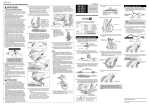
Spare parts list
SHIMANO NEXUS Revo-Shift Lever
SB-8S20
For 8-Speed
8
2
V
9
C R
3
4
1
5
7
6
11
10
12
13
1.2mm
2000m
m x100pc
SI-SP36B
s
SERVICE
INSTRUCTIO
SI-SP40
useread
Before use.
correct
NS
Outer
Casing
carefully,
and follow
them for
these instructions
inner
for an
designed be used for
is specially it can not
Notes:
casing
diameter
This outer1.1 mm in diameter;
mm in
cable of cable of 1.2
an inner
in diameter
MARK
cable of
1.1 mm
inner
packaging i
in bulk
s
grease
outer casingmust install will resu
You
SIS^SP36
resistance
internally.
Shimano
or cable
is not greased
outer casing
( sold separ
casing.
nside the shifting quality. outer cap
the outer
lt in poor SIS-SP36 sealed side of
the
derailleur
Install
the rear
atery )to
NO
MA
SHI
ON
TAL ATI
TO
EGR
INT
14
E
BL
R CA
INNE
SHIM
TOTAANO
INTE L
GRA
TION
INN
ER
CAB
LE
1.2 mm
2000 mm
(100 pcs.)
Q'TY
ITEM
NO.
1
2
3
4
5
6
7
8
9
10
11
12
13
14
SHIMANO
CODE NO.
Y-6J3 98010
Y-6J3 98030
Y-8TS 98010
Y-8S8 98010
Y-89E 05010
Y-61W98030
Y-8SB 10000
Y-6J3 04000
Y-61X 14010
Y-600 98510
Y-6Z2 98100
Y-620 98030
Y-6Z2 98010
Y-6Z1 90010
10 m / 32.8 ft.
1.2 mm
(100 pcs.)
DESCRIPTION
Indicator Cover & Fixing Screws (M3 x 5)
Upper Cover & Fixing Screw (M3 x 5)
R.H. Adjustment Block & Screw
Brake Cable Adjusting Bolt (M10 x 19) & Nut
Reach Adjusting Screw (M4 x 10.8)
Cable Adjusting Bolt Unit
Clamp Bolt (M6 x 14.8)
Shift Actuator (Black)
Half Grip ( 22.2 mm / Black)
Inner Cable Box (Stainless / 100 pcs.) for Shift
SIS-SP40 Outer Casing (Black) for Shift
Inner End Caps ( 1.2 mm / 100 pcs.)
SIS-SP40 Sealed Outer Caps (Revo-Shift Lever Side / Black / 6 mm / 100 pcs.)
SIS-SP40 Sealed Outer Cap (Cassette Joint Side / Silver / 6 mm)
IL/SB Printed in Japan 0302-2238
19
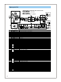
Spare parts list
SHIMANO NEXUS Cassette Joint
CJ-8S40
1
2
3
4
40
-8S
CJ
AN
P
JA
8
9
7
5
Q'TY
ITEM
NO.
1
2
3
4
5
6
7
8
9
SHIMANO
CODE NO.
Y-74Y 98160
Y-74Y 27000
Y-74Y 28000
Y-74Y 30200
Y-74Y 98140
Y-33Z 98020
Y-74Y 98150
Y-74Y 18000
Y-74Y 98030
6
DESCRIPTION
Outer Casing Holder Unit
Rubber Cover
Outer Casing Holder
Rubber Bellows
Cassette Joint Unit
Cassette Joint Fixing Ring
Cassette Joint
Driver Cap
Inner Cable Fixing Bolt Unit
IL/CJ Printed in Japan 0302-2237
20
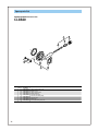
Spare parts list
SHIMANO NEXUS Brake Lever
BL-IM60
For Left Hand / 4-Finger
5
1
2
4
Q'TY
ITEM
NO.
1
2
3
4
5
SHIMANO
CODE NO.
Y-8TS 98020
Y-8S8 98010
Y-89E 05010
Y-8SB 10000
Y-89M08010
3
DESCRIPTION
L.H. Adjustment Block & Screw
Cable Adjusting Bolt (M10 x 19) & Nut
Reach Adjusting Screw (M4 x 10.8)
Clamp Bolt (M6 x 14.8)
Grip ( 22.2 mm / Black)
IL/BL Printed in Japan 0302-2239
21
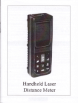
Spare parts list
SHIMANO NEXUS Tap-Fire Lever
ST-8S20
For 8-Speed
11
1.2mm
2000m
m x100pc
s
1
NO
MA
SHI
ON E
TAL ATI BL
EGR CA
R
INNE
TO
INT
SHIM
TOTAANO
INTE L
GRA
TION
INN
ER
CAB
LE
1.2 mm
2000 mm
(100 pcs.)
7
12
2
3
SI-SP36B
SERVICE
INSTRUCTIO
SI-SP40
useread
Before use.
correct
NS
Outer
these instructions
Casing
carefully,
and follow
them for
inner
for an
designed be used for
is specially it can not
Notes:
casing
diameter
This outer1.1 mm in diameter;
mm in
cable of cable of 1.2
an inner
in diameter
MARK
cable of
1.1 mm
inner
packaging i
in bulk
s
grease
outer casingmust install will resu
You
SIS^SP36
resistance
internally.
Shimano
or cable
is not greased
outer casing
( sold separ
casing.
nside the shifting quality. outer cap
the outer
lt in poor SIS-SP36 sealed side of
the
derailleur
Install
the rear
atery )to
4
11
8
8
10 m / 32.8 ft.
13
6
5
9
1.2 mm
(100 pcs.)
10
Q'TY
ITEM
NO.
1
2
3
4
5
6
7
8
9
10
11
12
13
14
15
SHIMANO
CODE NO.
Y-6JB 98010
Y-8TS 98010
Y-6JB 98030
Y-6JB 98040
Y-61W98030
Y-6JB 98050
Y-6JB 98060
Y-8SB 10000
Y-6JB 98070
Y-6JB 98080
Y-600 98510
Y-6Z2 98100
Y-620 98030
Y-6Z2 98010
Y-6Z1 90010
14
15
DESCRIPTION
Indicator Unit
R.H. Adjustment Block & Screw
Reach Adjusting Screw (M4 x 47) w/Cap
Brake Cable Adjusting Bolt (M10 x 19) & Nut
Cable Adjusting Bolt Unit
Cable Cover & Cover Fixing Screw (M2.5 x 4)
Tap Cover & Fixing Screw (M3 x 4)
Clamp Bolt (M6 x 14.8)
Lower Cover & Cover Fixing Screw (M3 x 12)
Main Lever Cover & Fixing Screw (M3 x 4)
Inner Cable Box (Stainless / 100 pcs.) for Shift
SIS-SP40 Outer Casing (Black) for Shift
Inner End Caps ( 1.2 mm / 100 pcs.)
SIS-SP40 Sealed Outer Caps (Shift Lever Side / Black / 6 mm / 100 pcs.)
SIS-SP40 Sealed Outer Cap (Cassette Joint Side / Silver / 6 mm)
IL/ST Printed in Japan 0305-2244
22
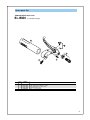
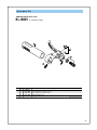
Spare parts list
SHIMANO NEXUS Brake Lever
BL-IM65
For Left Hand / 3-Finger
5
1
2
4
Q'TY
ITEM
NO.
1
2
3
4
5
SHIMANO
CODE NO.
Y-8TS 98020
Y-6JB 98040
Y-89E 05010
Y-8SB 10000
Y-89M08010
3
DESCRIPTION
L.H. Adjustment Block & Screw
Cable Adjusting Bolt (M10 x 19) & Nut
Reach Adjusting Screw (M4 x 10.8)
Clamp Bolt (M6 x 14.8)
Grip ( 22.2 mm / Black)
IL/BL Printed in Japan 0305-2245
23
SHIMANO AMERICAN CORPORATION
One Holland, Irvine, California 92618, U.S.A. Phone: +1-949-951-5003 Fax: +1-949-768-0920
Specifications are subject to change for improvement without notice.
This publication is printed on recycled paper.
MA34RB © Jan. 2004 Shimano Inc.
UCI official neutral
technical support
t