1
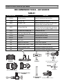
Air Source™
Service & Repair Manual
for Authorized Sea Quest Service Centers
Doc. No. 42965, Rev. 8/99
©1999 Sea Quest, Inc.
Contents
Introduction .................................................................................................................................................................... 3
Safety Precautions .......................................................................................................................................................... 3
General Procedures ........................................................................................................................................................ 3
Maintenance Schedules .................................................................................................................................................. 3
Initial Inspection and Pre-Test ...................................................................................................................................... 3
Work Area & Required Tools ........................................................................................................................................ 4
O-ring Removal ....................................................................................................................................................... 4
Table 1 - Recommended Tools ....................................................................................................................................... 6
Table 2 - Lubricant & Cleaner ...................................................................................................................................... 6
Air Source Overhaul Procedures .................................................................................................................................. 7
1.1 Air Source Disassembly ................................................................................................................................... 7
1.2 Cleaning & Inspection ...................................................................................................................................... 9
1.3 Air Source Reassembly .................................................................................................................................. 10
1.4 Adjustment & Assembly ................................................................................................................................. 15
Flow testing Procedures ............................................................................................................................................... 16
Bench Testing ........................................................................................................................................................ 16
Vacuum Leak Test ................................................................................................................................................. 17
Testing Without a Test Bench ................................................................................................................................ 17
Subjective Breathing Test ...................................................................................................................................... 17
Vacuum Leak Test ................................................................................................................................................. 17
Air Source Troubleshooting ......................................................................................................................................... 18
Table 3 - Test Bench Specifications ............................................................................................................................. 19
Air Source Parts List .................................................................................................................................................... 21
Air Source Schematic ................................................................................................................................................... 22
Sea Quest Air Source Service and Repair Manual
INTRODUCTION
Sea Quest buoyancy compensators and regulators are the product of many years of research and development. Sea Quest has
utilized proven materials and design to maximize reliability and
performance.
This manual is intended only as a guide for the experienced
repair person that has completed a Sea Quest service and repair
seminar. It is not intended to educate inexperienced repair personnel or the consumer in all aspects of Sea Quest regulator and
buoyancy compensator repair. Sea Quest repair seminars are
available periodically to Authorized Sea Quest Dealers. Servicing and repair at the repair shop level mainly involves cleaning, inspection, adjustment, and replacement of worn parts.
3
GENERAL PROCEDURES
MAINTENANCE SCHEDULES
Regulators and inflation systems are subjected to a variety of
environmental elements that over time can affect the performance
of the product and as such require frequent tuning and adjustment. As an Authorized Sea Quest Dealer you are advised to
inform your staff and customer that Sea Quest regulators and
buoyancy compensators require complete servicing at least once
a year. Under certain circumstances a complete servicing is
required every 3-6 months. Some of these circumstances are:
Frequent or improper use
● Inadequate routine freshwater rinsing
● Regulator use in dirty or polluted waters
● Rental use
● Regular use in chlorinated (pool) water
●
If you have any questions on any of the procedures, inspections, or tests, please contact Sea Quest at (877) 253-3483.
SAFETY PRECAUTIONS
This manual provides step by step instructions for the disassembly, inspection, cleaning, reassembly, and testing of the Air
Source™ second stage/ inflation system. It is recommended that
all steps are followed in the order given. Read each section
completely PRIOR to beginning work described in that section.
This will familiarize the repair technician with important precautions to take during each service procedure.
Pay close attention to all WARNINGS, CAUTIONS, and
NOTES that are intended to draw your attention to items of
importance.
Definition of Warnings, Cautions, and Notes:
Recommended maintenance schedules are based on average use
under normal conditions and assume that recommended preventative maintenance and storage procedures have been followed as outlined in the Sea Quest owner’s manuals.
Advise the customer that any adjustments or servicing on Sea
Quest regulators and buoyancy compensator inflation systems
must be performed by Sea Quest, or by an Authorized Sea Quest
Dealer that has attended a Sea Quest regulator service seminar.
INITIAL INSPECTION AND PRE-TEST
Prior to beginning the servicing of the Sea Quest Air Source, a
preliminary inspection and pre-test of the entire breathing system is recommended. This will help the repair technician identify any problems that may affect the Air Source™ second stage.
Preliminary inspection should include:
First stage inlet filter - If the first stage inlet filter is discolored or corroded, the entire regulator should be completely serviced. Deposits of rust (red powder) or aluminum oxide (gray
powder) on the filter may indicate that water has entered the
SCUBA cylinder and caused internal cylinder corrosion. The
customer should be notified that their SCUBA cylinder(s) may
be in need of visual inspection, cleaning and testing. Advise
your customers to regularly inspect the inlet filter for any discoloration or corrosion.
●
Indicates a procedure or situation that may result in serious injury or death for either the technician or the user if
instructions are not followed correctly.
Indicates any situation or technique that may result in potential damage to the product, or render the product unsafe if instructions are not followed correctly.
NOTE
Is used to emphasize important points and tips.
High pressure (HP) and low pressure (LP) hoses - Inspect
the hoses carefully for any evidence of cracking, tearing, or excessive abrasion of the outer rubber covering. Remove all of
the hose protectors and examine the area around the metal fittings for any damage to the hose. Inspect the fittings for signs
of excessive corrosion.
● All chrome plated parts - Inspect for any excessive corrosion indicating weak or absent chrome plating. Also look for
any signs of peeling or flaking of the chrome plating.
● Regulator pre-test - A regulator pre-test should include all
tests outlined in the test section for each regulator. A pre-test
will assist the technician in determining if there are any specific
performance deficiencies not mentioned by the customer.
●
4
Sea Quest Air Source Service and Repair Manual
INFREQUENTLY USED AIR SOURCES AND
BUOYANCY COMPENSATORS
Do not assume that the Air Source or buoyancy compensator is
in good condition because of infrequent use or because it has
been in storage. Deterioration of the O-rings and corrosion can
still occur under these circumstances.
Do not use any petroleum based lubricants or products, or
any aerosol silicone sprays to lubricate or clean any part of
Sea Quest regulators or inflation systems. The petroleum
base or propellant gas may attack or weaken the plastic or
rubber parts. Refer to Table 2 for approved lubricants.
WORK AREA & REQUIRED TOOLS
Servicing and repair of the Sea Quest Air Source should be carried out in a clean well lighted work area. As each regulator is
disassembled all parts should be kept separate from parts of other
regulators. Some special tools are required for proper disassembly and reassembly of the Sea Quest Air Source. Please see
Table 1 (page 5) for a list of these tools.
O-RING REMOVAL
When removing O-rings, care must be taken to not damage the
regulator surfaces in contact with the O-rings. Tools used to
remove O-rings must not have any sharp edges or points that
could scratch metal sealing surfaces. Sea Quest strongly recommends that all O-ring removal tools should be made of either brass or plastic.
LUBRICATION
O-rings should be lubricated with an approved compound (please
refer to Table 2 for proper lubricants). O-rings should be lubricated only with a very light film of silicone grease. Do not use
spray (aerosol) silicone under any circumstances. The aerosol
propellant may damage the plastic and rubber components of
the regulator, and the lubricant will quickly evaporate, providing little or no lasting benefit.
Sea Quest regulators and inflation systems are intended for
use in water temperatures warmer than 45ºF (7ºC). Colder
water may cause regulators to be more sensitive to a freeflow
condition and can lead to a situation that requires an appropriate response to prevent serious injury or death. Users of
Sea Quest regulators are advised to ensure that they are adequately trained to deal with a regulator in a freeflow condition or an out-of-air emergency before attempting to dive in a
cold water environment.
Sea Quest Air Source Service and Repair Manual
5
RECOMMENDED TOOLS - AIR SOURCE
TABLE 1
Sea Quest Part No.
Description
Application
5116236
Seal/seat extractor
Removal/ installation of crown and filter
778694
Valve Core Tool
Removal/ installation of valve core
42314
Air Source T-Tool
Removal/ installation of inflation valve bezel, quick
disconnect fitting, and crown adjustment
42315
Air Source Multi-Tool
Removal/ installation of purge button and retaining
ring, exhaust cap, and assembly of poppet w/ lever
42316
Air Source Oral Assembly Tool
Assembly of oral valve
41016
Inline Crown Adjustment Tool
Adjustment of opening effort
1116-10
I.P. test gauge
Intermediate pressure testing
9440-22
O-ring tools
O-ring removal & installation
41532
LP air nozzle
Parts drying
N/A
Magnifier w/ illumination
Sealing surface inspection
N/A
Ultrasonic cleaner - 60HZ, 1.3 amp
Brass & stainless steel parts cleaning
N/A
Phillips Screwdriver (small)
Disassembly/ assembly of oral valve seal
N/A
4" nut driver
Disassembly/ assembly, adjustment of locknut
TOOLS
TOOLS
TOOLS
Multi-Tool
P/N 42315
Poppet & lever reassembly
T-Tool
P/N 42314
Removal/ installation of inflation valve
bezel & quick disconnect fitting
TOOLS
.740"±.010"
Purge cover removal/ installation
Crown pre-set
Exhaust cap removal/ installation
Inline Crown Adjustment Tool
P/N 41016
Oral Assembly Tool
P/N 42316
Assembly/ installation of oral valve
Sea Quest Air Source Service and Repair Manual
6
LUBRICANT AND CLEANER
TABLE 2
Lubricant / Cleaner
Recommended Type
Application
Source
Silicone Grease
(food grade)
Dow Corning 111
All O-rings,
threaded metal parts
as indicated
Dow Corning Corp
P.O. Box 1767-T
Midland, MI 48640
800-248-2481
Chemical Bath Solution
Oakite #31
Chrome-plated brass,
brass, and stainless
steel parts
Oakite Products, Inc.
50 Valley Road
Berkeley Heights, NJ 07922
Acetic Acid
50/50 mix distilled
white vinegar and water
Chrome-plated brass,
brass, and stainless
steel parts
Local grocery stores
General cleaning solution,
degreaser for plastic
and rubber parts,
leak detection
Local grocery stores
Liquid dishwashing detergent Joy®
(diluted with warm water)
DO NOT use muriatic acid for the cleaning of any parts. Muriatic acid, even when strongly diluted, can
harm chrome plating, and may leave a residue that is harmful to O-ring seals and other parts.
Aerosol spray silicone should be avoided because (1) common aerosol propellants may attack plastic
and rubber parts, and (2) because only a slight amount of silicone remains after the solvent evaporates, and provides no lasting benefit.
Silicone rubber requires no lubrication or preservative treatment. DO NOT apply silicone grease or
spray to silicone rubber parts. Doing so will cause a chemical breakdown and premature deterioration of the material.
Sea Quest Air Source Service and Repair Manual
7
AIR SOURCE
1.1 AIR SOURCE DISASSEMBLY
1.1.1 Closely examine the condition of the mouthpiece to ensure it is free of any tears or cuts that may cause leakage of
water into the second stage, or other discomfort. If replacement
is not needed, it is not necessary to remove the mouthpiece from
the body. It may otherwise be removed by placing a wide blade
screwdriver inside the mouthpiece, just beneath one of the retainers(28). While holding the body secure, firmly press the
flat of the screwdriver upward against the retainer until it exits
the body, and lift it out to remove. Do not attempt to pry the
retainer out from above. Repeat the above procedure to remove
the opposite retainer, and twist the mouthpiece off of the body
to remove. Inspect the retainers to check for any signs of wear
or damage, and replace if found.
Figure 2
1.1.8 While holding the body secure, place a 4" nut driver
over the lock nut(44) of the valve poppet, and slowly press inward until the valve begins to exit the opposite end of the body
(see Fig. 3). Be careful to avoid pressing it completely out.
1.1.2 Snip the clamp(19) which holds the spiral hose(16) onto
the lower valve assembly, and work the hose off the Air Source
body(26) to expose the cable retaining pin(21).
1.1.3 Press the pin out from one side with a pin punch or similar tool, and set the pin and upper valve assembly aside.
1.1.4 Rotate the purge button(48) as needed to align the two
opposing slots with the slots in the diaphragm retainer(47) beneath it. Mate the flat tabs of the Air Source Multi-Tool (P/N
42315) through the slots of the purge button and into the diaphragm retainer (see Fig. 1). While holding the tool securely
engaged, turn the purge button and retainer counter-clockwise
to loosen and remove both parts as one assembly.
Figure 3
1.1.9 When the crown housing(7) has appeared outside of the
body, firmly grasp the end between thumb and forefinger, and
gently pull it straight out to remove the entire valve module.
Be careful to avoid stressing the lever as the valve module
exits the body.
1.1.10 While holding the poppet housing(11) of the valve module secure with one hand, firmly grasp the crown housing and
pull straight away to separate these two parts. Set the poppet
housing aside.
Figure 1
1.1.5 Inspect the retainer and purge button to ensure they are
perfectly round and do not show any signs of deterioration or
damage, especially around the threads of the retainer. If replacement of either part is necessary, pull them apart by hand.
1.1.11 While holding the crown housing secure, insert the pin
of the seat/seal extractor (P/N 5116236) through the open center of the crown inside the housing, and press out the filter(2).
(See Fig. 4.) Remove all four external O-rings(5&6), including
one which may have remained inside the poppet housing. Discard these with the filter, and do not attempt to reuse.
1.1.6 Lift out the diaphragm(45) and diaphragm ring(46), and
set the ring aside. Closely inspect the diaphragm to ensure that
it is perfectly round and free of any tears, deterioration, or other
damage. If damage or deterioration is found, discard and do not
reuse.
1.1.7 Mate the pins on the small end of the Air Source T-Tool
(P/N 42314) into the bore holes on both sides of the quick disconnect fitting(1). While holding the tool securely engaged,
turn the fitting counter-clockwise to loosen and remove (see
Fig. 2). Inspect the fitting for any signs of damage, and set it
aside to be reused if none are found.
Figure 4
1.1.12 While holding the crown housing secure, apply a medium blade screwdriver to the slotted head of the removable
crown(4), and turn the crown completely out (approximately 810 full turns) counter-clockwise to disengage its threads.
Sea Quest Air Source Service and Repair Manual
8
Because the crown is O-ring sealed, it will not freely
NOTE exit the valve body after it has been unthreaded. The
following step must be performed correctly in order
to remove the crown without damaging its delicate
sealing surface.
1.1.13 When the crown has been unthreaded from the crown
housing, insert the large, blunt end of the seal/seat extractor (P/
N 5116236) through the opposite end of the crown housing, and
gently press out the crown (see Fig. 5). Remove and discard the
crown O-ring(3).
Figure 6
The Air Source has undergone a design revision of
NOTE several components (refer to the schematic draw-
Figure 5
1.1.14 Closely examine the crown with the use of magnifier,
checking for any signs of nicks or other damage to the polished
sealing surface. If damage is found, discard the crown, and do
not attempt to reuse. If it is in reusable condition, set it aside on
a soft surface to prevent damage to the sealing edge.
1.1.15 Place a finger over the open end of the poppet housing
to prevent the ejection of spring loaded parts. While holding
the poppet housing secure, apply a 4" socket with hand driver
to the lock nut(44), and turn counter-clockwise to loosen and
remove the locknut, lever(42) and washer(43). Discard the locknut and do not attempt to reuse.
ing). Units manufactured before June, 1999 may
require the installation of the Revision B Upgrade
Kit, in addition to the annual service parts kit. When
performing overhaul service, it is important to correctly identify each unit as instructed in the next step,
to determine whether it requires this upgrade.
1.1.21 Closely examine the inner surface of the button cover
and the top surface of the inflator bezel to determine whether
these are current revision parts (see Fig. 7). If the inner surface
of the button cover contains four raised dots and the top surface
of the inflator bezel contains four bore holes, they are of the
current revision and can be reused if no signs of wear or damage are visible. If either of these cannot be identified as a current revision part, it is very important to discard and replace
both of them as a set, in addition to several other parts which are
provided in the Revision B Upgrade Kit – P/N 42642.
1.1.16 Inspect the lever and washer for any signs of wear or
damage. If wear or damage is found, replace these items and do
not attempt to reuse.
1.1.17 Turn the poppet housing over to allow the poppet(9)
and spring(10) to fall out. Closely inspect the poppet spring
under strong magnification to check for any signs of damage or
corrosion. If it is found to be damaged (bent) or corroded, discard and do not attempt to reuse.
1.1.18 Using a plastic or brass O-ring tool, lightly stick the
center of the LP seat(8) inside the head of the poppet, and lift
the seat out. Discard the seat, and inspect the head of the poppet to check for any nicks, scratches, or other signs of damage.
If any signs of damage are found, discard the poppet and do not
attempt to reuse.
1.1.19 Closely inspect the poppet guide(12) to ensure that it is
square in its center, and seated flush inside the flanges of the
poppet housing. If any signs of deformation or damage are found,
it may be pressed out from inside and discarded, using a 4.5 mm
plastic or wood dowel. It is otherwise not necessary to remove
the poppet guide for annual service and cleaning.
1.1.20 Mate the pins on the large end of the Air Source T-Tool
into two opposing holes in the inflator bezel(36). (See Fig. 6.)
While holding the tool securely engaged, turn the bezel counterclockwise to loosen and remove the bezel, inflator button(34),
inflator button cover(35), and spring(33). Separate the button
and button cover from the bezel, and set the button aside.
Revision A
(original - do not reuse)
Revision B
(okay to reuse)
Figure 7
The new bezel and button cover "Revision B" have been revised to provide improved retention of the inflator button. Do
not attempt to reuse the original bezel or cover under any
circumstances. Doing so may cause the failure of the inflator
valve assembly, and could lead to a loss of buoyancy control.
(Refer to Technical Bulletin, dated November 3, 1997.)
1.1.22 Closely inspect the spring under strong magnification
to check for any signs of damage or corrosion. If it is found to
be damaged (bent) or corroded, discard and do not reuse.
1.1.23 Firmly grasp the valve core(32), using a pair of small
needle nose pliers, and pull straight out of the body to remove
the valve core and valve core retainer(31).
1.1.24 Remove both O-rings(30&29) from the valve core retainer and the recess inside the body, and discard.
1.1.25 While holding the valve core retainer secure, apply the
Sea Quest Air Source Service and Repair Manual
Valve Core Tool (P/N 42303) to turn the valve core counterclockwise. Remove and discard the valve core. Do not reuse.
1.1.26 Mate the pins of the Air Source Multi-Tool into the oral
valve exhaust cap(41). (See Fig. 8.) While holding the tool
securely engaged, turn the cap counter-clockwise to loosen and
remove. Closely inspect the cap for any signs of damage, especially around the threads. If found, discard it and do not reuse.
9
1.1.31 Remove the button cover from the button poppet, and
closely inspect the cover to check for any signs of damage or
wear, including tears, abrasion, or decay. If found, discard the
cover and do not reuse.
1.1.32 Closely inspect the spring under strong magnification
to check for any signs of damage or corrosion. If it is found to
be damaged (bent) or corroded, discard it and do not reuse.
1.1.33 Closely inspect the poppet for any signs of damage,
especially around the hex stem. If it appears damaged due to
stress or improper tool engagement, discard it and do not reuse.
1.1.34 Closely inspect the bezel for any signs of damage, especially around the threads and hex opening in the center. If it
appears damaged due to cross-threading or excessive torque,
discard it and do not reuse.
Figure 8
1.1.27 Remove the exhaust valve diaphragm(40) from the diaphragm retainer(39), and discard.
1.1.28 Turn the diaphragm retainer counter-clockwise by hand
to loosen and remove from the body. Closely examine the retainer to check for any cracks, distortion, or other signs of damage; especially around the threads and spokes. If damage is
found, discard the retainer and do not attempt to reuse.
1.1.29 While holding the body secure, apply a small Phillips
screwdriver to the oral seal screw(38) which is visible through
the exhaust port, and turn counter-clockwise to loosen and remove. Set the screw aside, and turn the body over to allow the
washer(37a) and oral seal assembly(37) to fall out of the large
end. Discard the oral seal assembly and do not attempt to reuse.
1.1.35 Closely examine all features of the body, especially at
the threaded openings which contain the power button and oral
button assemblies, and quick disconnect fitting. Check for any
signs of cross-threading, excessive torque, or other damage. If
any damage is found, discard the body and do not reuse.
1.2 CLEANING & INSPECTION
1.2.1 All parts should be cleaned first in a warm (not over
120°F) mild soap and water solution. Use a soft nylon bristle
brush to help remove any excess or loose contamination. After
an initial warm water and soap cleaning all parts should be thoroughly rinsed in clean fresh water and dried with filtered low
pressure (30 psig) air. After an initial cleaning in warm soap
and water solution, metal parts should be cleaned in an ultrasonic cleaner using the appropriate ultrasonic cleaning solution
(see Lubricant and Cleaner Table 2).
Be sure all O-rings and other rubber or plastic parts
NOTE
Units manufactured before October, 1998, may not
contain the oral seal washer (key #37a). It is important to install this part, however, when replacing the
oral seal assembly.
1.1.30 While holding the oral valve button lightly depressed to
prevent the ejection of parts, apply a 4" nut driver to the stem
of the oral button poppet(23). While holding the nut driver securely engaged, turn the oral poppet counter-clockwise to loosen
and remove the oral bezel(25) (see Fig. 9). When the bezel has
disengaged the body, slowly relax the button to allow the button
cover(22), button poppet(23), spring(24), and bezel to fall out.
NOTE are removed before cleaning in an ultrasonic cleaner
or chemical bath. Cleaning solutions may damage
these components.
1.2.2 If an ultrasonic cleaner is not available, metal parts can
be cleaned by soaking the metal parts in a chemical bath solution of Oakite #31 (see Lubricant and Cleaner Table 2) and agitating gently for 3-4 minutes. Cleaning of metal parts can also
be done by soaking in a mild acetic acid solution (distilled white
household vinegar) for 10-15 minutes.
Cleaning times in excess of those recommended
NOTE may damage plated parts. Never clean parts for
longer than specified by the manufacturer of the
solution used. After completion of cleaning in any
solution, thoroughly rinse parts with clean fresh
water and blow dry with low pressure (30 psig) air.
Only brass, plated brass, and stainless steel parts
should be immersed in chemical cleaning solutions.
Figure 9
Use hand and eye protection when handling chemical cleaning solutions.
Sea Quest Air Source Service and Repair Manual
10
1.2.3 After cleaning, all parts should be thoroughly rinsed in
fresh water and dried with filtered low pressure (30 psig) air.
NOTE
Before performing any reassembly, it is important
to inspect all parts, both new and those that are being reused, to ensure that each part is clean and
free of any contamination, corrosion, or blemish.
1.2.4 All O-rings should be replaced at every servicing. New
O-rings should be inspected for contamination and/or imperfections, and lightly dressed with a thin film of approved lubricant prior to installation. (See Lubricant and Cleaner Table 2.)
Do not use any petroleum based lubricants or products, or
any aerosol silicone sprays on any part of Sea Quest regulators. The petroleum base or propellant gas may attack or
weaken plastic or rubber parts. Refer to Table 2 for a list of
approved lubricants.
1.2.5 In addition to the O-rings, the following parts should be
routinely replaced at the time of servicing:
● Sintered Filter (2)
● Poppet Seat (8)
● Clamp (19)
● Valve Core (32)
● Locknut (44)
● Exhaust Valve Diaphragm (40)
All O-rings and the above mentioned routine replacement parts
are included in the Overhaul Service Kit (P/N 42608).
1.2.7 If any of the listed parts show any damage, they must be
replaced with new.
1.2.8 Check all metal parts for excessive wear or corrosion.
Check all metal sealing surfaces which make contact with Orings for any signs of contamination and/or imperfections that
may cause leakage past the O-ring seal. Examine all chrome
plated surfaces for any evidence of peeling or flaking of the
chrome plating. Inspect all threads for galling, cross threading,
or damage to the chrome plating. If any parts show damage or
excessive wear, they must be replaced with new.
1.3 AIR SOURCE REASSEMBLY
Use only genuine Sea Quest parts, subassemblies, and components whenever assembling Sea Quest products. DO NOT
attempt to substitute a Sea Quest part with another
manufacturer’s, regardless of any similarity in shape, size, or
appearance. Doing so may render the product unsafe, and
could result in serious injury or death.
1.3.1 Fit the mouthpiece(27) onto the body(26), and press both
retainers(28) firmly into place so they are seated flush inside
their recessed holes.
1.3.2 Stand the oral button poppet(23) with the stem facing up,
and place the spring(24) over the poppet stem.
1.3.3 Examine the features of the oral bezel(25) to identify the
recess in which the spring seats, and place the bezel over the
poppet stem with the recess facing down.
1.2.6 The following parts should be closely inspected for the
damage listed below. Close inspection is best accomplished by
using a jeweler’s magnifying loop under bright lighting.
● Orifice Crown (4) Inspect the cone area for nicks, scratches,
pitting, or any defects in the plating. Pay particular attention to
the sealing edge of the cone.
● Poppet (9) Inspect for corrosion, pitting, scratches, defective plating or excessive wear, particularly inside and around
the cavity which holds the LP seat.
● Springs (10, 24, & 33) Inspect for cracks or broken coils.
● Demand lever (42) Compare with new to inspect for bending, distortion, or deformities of the white friction button.
1.3.4 Drop the oral seal screw(38) into the open end of the
Oral Assembly Tool (P/N 42316), so that the tip protrudes out
of the slotted end. Place the slotted end of the tool directly
above the center of the bezel and slowly press the tool down,
rotating it in either direction if necessary, until it fully engages
with the hex of the poppet. While holding the tool and bezel
depressed, insert a small Phillips screwdriver through the open
end of the tool, and gently thread the screw clockwise into the
poppet (see Fig. 10). After ensuring that the screw is correctly
threaded, continue turning it clockwise only until lightly snug,
and remove the screwdriver. The bezel should now be held
securely in place while the tool is temporarily installed over it,
with the spring compressed beneath it to facilitate the installation of the button cover.
Demand diaphragm (45) Inspect for cracking, tears, or pinholes. To detect pinholes, hold diaphragm up to a light source
as you gently stretch the diaphragm. Inspect the round plastic
diaphragm plate for any evidence of damage.
● Button covers (22 & 36) Inspect for cracking, tears, or pinholes. Closely examine the sealing lip to check for any signs of
damage or distortion.
● Mouthpiece (29) Inspect for cracking or tears or any excessive wear especially around the bite tabs.
● Body (26) Inspect for any indication of cracks or thread
damage. Closely examine the seating ledge which indexes with
the poppet housing, to ensure it is free of any distortion or other
damage. (Refer ahead to Fig. 25 on page 14.)
Figure 10
●
Sea Quest Air Source Service and Repair Manual
Over-tightening the screw will strip the threads of the oral
button poppet, requiring its replacement. The oral seal
assembly may otherwise become loosened from the oral
button assembly, rendering the oral valve inoperable.
1.3.5 Fit the oral button cover(22) over the head of the poppet,
and gently work the lip of the button cover over the ridge of the
bezel, until it is evenly seated all around (see Fig. 11).
11
Do not cross-thread or overtighten the oral bezel during installation. Failure to correctly install the oral valve assembly
may cause permanent damage to the bezel, poppet, or body,
requiring the replacement of these parts. Leakage may otherwise result from using these parts in damaged condition.
1.3.9 Examine the oral seal assembly(37) to identify the raised
sealing ridge which surrounds the hole on one side (see Fig.
14). Guide the seal into place through the large opening of the
body, so that the sealing ridge is facing down directly over the
poppet stem of the oral button assembly, and the flat, non-sealing
side is facing up. Lay the washer(37a) inside the recess so that
it is centered directly over the hole.
Figure 11
1.3.6 Insert the open end of the tool into the oral valve hole in
the body, and pull it out through the exhaust port on the opposite side (see Fig. 12). Rotate the button assembly slightly back
and forth as needed to seat the cover inside the body. While
pressing the button inward, turn the tool clockwise to engage
the threads, and tighten the bezel into the body until finger snug.
Non-sealing side
Sealing Ridge
Figure 13
1.3.10 Insert the screw(38) through the washer and the hole in
the center of the seal assembly, and into the poppet stem of the
oral button. Carefully begin threading the screw clockwise by
hand to ensure proper threading. While holding the oral button
completely depressed, apply a small Phillips head screwdriver
to turn the screw further clockwise only until lightly snug. Check
to ensure that the oral seal assembly is tightened flush against
the end of the button poppet, and relax the button.
Over-tightening the screw will strip the threads of the oral
button poppet, requiring its replacement. The oral seal assembly may otherwise become loosened from the oral button assembly, rendering the oral valve inoperable.
Figure 12
1.3.7 While holding the oral button completely depressed, insert a small Phillips screwdriver through the tool to engage with
the screw. Turn the screw out counter-clockwise to loosen and
remove, and set the screw, screwdriver, and oral valve assembly tool aside.
1.3.11 Closely examine the exhaust diaphragm retainer(39) to
identify the flat sealing surface (top), which is opposite the side
that is recessed (bottom). (See Fig. 14.) Insert the stem of the
diaphragm(40) through the center hole in the top of the retainer,
and gently pull the stem through the retainer only as far as is
necessary to seat the barb on the recessed side. Snip off the
excess portion of stem just above the barb to prevent any
obstruction of the oral seal.
It is very important to hold the oral button completely
NOTE depressed while removing the screw, in order to prevent the poppet threads from becoming stripped.
1.3.8 Apply a 4” nut driver to the stem of the poppet, and turn
the poppet clockwise to tighten the bezel lightly snug. Remove
the nut driver, and closely inspect the button cover to ensure
that it is seated evenly on all sides, and does not appear to be
cocked or partially unseated.
Sealing Side (Top)
Figure 14
Bottom
Sea Quest Air Source Service and Repair Manual
12
1.3.12 Fold both sides of the diaphragm upward to grasp the
top of the retainer with thumb and forefinger. Mate the retainer
into the exhaust port of the body, and turn clockwise by hand
only until lightly snug. Do not overtighten.
1.3.13 Mate the exhaust cap(41) into the exhaust port of the
body, and turn clockwise by hand to engage the threads. Mate
the pins of the Air Source Multi-Tool (P/N 42315) into the oral
valve exhaust cap(41). While holding the tool securely engaged,
turn the cap clockwise until it is snug and flush against the body
(see Fig. 15). Do not overtighten.
Figure 15
1.3.14 Examine the features of the valve core retainer(31) to
identify the stem and two positioning tabs on its underside, and
the recessed hole on top. While holding the retainer secure,
thread the valve core(32) by hand into the recessed hole, and
apply the Valve Core Tool (P/N 42303) to tighten it snug.
1.3.17 Place the spring(33) directly over the valve core, in the
center of the valve core retainer.
1.3.18 Insert the button cover(35) through the threaded side of
the inflator bezel(36), so that the sealing lip of the cover is seated
evenly inside the bezel. Place the power inflator button(34)
inside the button cover, with the spring mating tap facing out.
To prevent the button cover from binding or crimp-
NOTE ing as the bezel is tightened into the body, Sea Quest
recommends wetting the button cover with isopropyl alcohol before inserting it into the bezel.
1.3.19 Hold these parts together, and position them centered
directly above the inflator spring and valve core, so that the
spring mates over the tab of the inflator button. Press the button
and bezel straight down over the spring with thumb and forefinger. While holding the button depressed, gently thread the bezel clockwise by hand into the body until lightly snug. Apply
the pins on the large end of the Air Source T-Tool (P/N 42314)
to the bezel. While holding the tool securely engaged, turn the
bezel clockwise until it is flush with the surface of the body (see
Fig. 18). Do not overtighten. Closely inspect the button cover
to ensure that it is seated evenly on all sides, and does not appear to be cocked or partially unseated.
Do not overtighten the valve core into the retainer. Doing so
may strip the retainer's threads, requiring its replacement.
1.3.15 Install the O-ring(30) over the positioning tabs and flush
against the shoulder of the underside. Install the O-ring(29)
over the stem of the retainer so that it seats flush against the
base (see Fig. 16).
O-rings
Figure 16
1.3.16 Place the stem of the valve core retainer inside the open
port of the body, and gently align it so that the crescent shaped
opening is centered above the crescent shaped recess of the body.
Press the retainer evenly into place, so that both positioning tabs
seat securely inside the slots of the body (see Fig. 17).
Figure 17
Figure 18
1.3.20 If the poppet guide(12) was removed from the poppet
housing(11), it will be necessary to install a new replacement
part into the recessed end of the housing. Ensure that it is properly aligned with the stem facing in between the two crescent
flanges, and press it firmly into place.
1.3.21 Lay the poppet seat(8) at an angle inside the head of the
poppet, and then pull back the edge on one side to release any
air behind it while firmly pressing it into place. Check to ensure it is seated completely flush with the outer rim of the poppet on all sides, and correct if needed before proceeding.
1.3.22 Place the poppet spring(10) over the stem of the poppet(11), and insert the stem of the poppet into the open end of
the housing. Hold these parts together, and place the open end
of the housing directly over the poppet assembly post of the Air
Source Multi-Tool (P/N 42315). (See Fig. 19.)
Sea Quest Air Source Service and Repair Manual
13
Figure 21
Figure 19
1.3.23 Gently pull the poppet housing down over the post until it is flush with the base of the tool to compress the spring
inside. Do not use force to press the poppet stem through the
guide in the end of the housing.
If the poppet does not move freely through the guide
NOTE in the end of the housing, it will be necessary to
rotate it slightly in either direction to align the square
stem of the poppet with the square hole of the guide.
1.3.27 If necessary, apply a 4" nut driver to turn the locknut
clockwise until 1-2 threads of the poppet stem are visible. Remove the nut driver and set the poppet housing aside.
1.3.28 Install all four O-rings(5&6) onto their respective
grooves in the crown housing(7).
1.3.29 Install the O-ring(3) onto the crown(4), and carefully
insert the threaded end of the crown into the larger, unthreaded
end of the crown housing. Gently press it in further with the
blunt end of the seal/seat extractor (P/N 5116236) until it stops
(see Fig. 22.)
1.3.24 While holding the poppet housing depressed over the
assembly post, place the washer(43) over the stem of the poppet, followed by the locknut(44). Thread the locknut clockwise
by hand onto the poppet until one thread of the stem is visible.
1.3.25 Closely examine the features of the poppet housing to
identify the two airflow ports on opposite sides; one which is
oval, and the other which is circular. Also, locate the squaredoff seating ledge just below the circular port, which indexes
with the body (see Fig. 20). Position the poppet housing over
the assembly post with the oval port facing toward six o’clock.
Circular Port
Figure 22
1.3.30 Apply the crown adjustment feature of the T-Tool to
turn the crown in clockwise as far as the tool will allow, and
then turn the crown back counter-clockwise exactly 2 turn to
arrive at the correct preliminary setting (see Fig. 23).
Oval Port
Seating
Shoulder
Figure 20
1.3.26 Position the lever(42) above the poppet housing so that
the button faces toward 12 o’clock, in the same direction as the
circular port of the housing (see Fig. 21). Gently pull the housing down over the assembly post once again, and hold it depressed with one hand to compress the poppet spring. Lay the
forks of the lever beneath the washer and locknut and between
the two flanges, and slowly relax pressure on the poppet spring
while watching to ensure that the lever rises and stands upright.
Figure 23
If the T-Tool is not available, a medium blade screw-
NOTE driver may be used to turn the crown exactly 4 turns
clockwise from the first thread. Sea Quest strongly
recommends that the T-Tool be used, however, in
order to preset the crown more precisely.
14
Sea Quest Air Source Service and Repair Manual
1.3.31 Position the crown housing behind the poppet housing,
with the crown facing inward toward the LP seat, and carefully
insert the crown housing into the poppet housing (see Fig. 24).
Press firmly together until both parts are flush with each other.
NOTE connect fitting is a current revision part (P/N 15111),
Before proceeding, check to ensure the quick diswhich is provided in the Revision B Upgrade Kit mentioned in Step 1.1.21. The current revision part has
a larger flange, which helps to prevent any damage
that may be caused by overtightening. Do not attempt to reuse a Revision A fitting. (See Fig. 26.)
New
(larger flange)
Old
(smaller flange)
Figure 24
Figure 26
If the O-ring(5) seems to bind or otherwise comes
NOTE unseated as the crown housing passes into the poppet housing, disassemble and correct as needed
before proceeding further. Leakage may otherwise
result if the O-ring is not correctly seated.
1.3.32 Closely examine the barrel inside the body which houses
the valve module, to identify the flat ledge inside which indexes
with the seating shoulder of the poppet housing. Align the valve
module accordingly outside the barrel of the body, so that the
ledge inside the body faces straight up and the shoulder of the
poppet housing faces straight down (see Fig. 25). Gently insert
the valve module (lever first) into the barrel, being careful to
guide the end of the lever through without obstruction. Check
first to ensure that the poppet housing is aligned precisely with
the body, and carefully press the valve module straight inward.
Do not use force. Closely inspect afterward to ensure the shoulder of the poppet housing fits squarely over the ledge inside the
body, and is not cocked to either side. The end of the crown
housing should also be flush with the outer surface of the body.
1.3.33 Remove the knob from the shaft of the Air Source Inline
Adjustment Tool (P/N 41016), and pull the shaft completely out
of the tool body. Place the quick disconnect fitting(1) over the
narrow end of the shaft, with the nipple facing up, and slide it
down to the opposite end. Then, mate the male threads of the
quick disconnect fitting over the crown housing and into the
body, and turn clockwise by hand to engage the threads.
1.3.34 Place the narrower end of a modified (drilled) or current (purchased after July 1, 1999) T-Tool over the adjustment
shaft, and mate the two small pins into the holes of the quick
disconnect fitting. While holding the tool securely engaged,
tighten the fitting clockwise until it is snug and its flange is
seated flush against the body (see Fig. 27). Do not overtighten.
Figure 27
The Adjustment and Final Assembly procedure re-
NOTE quires the use of the Air Source Inline Adjustment
Ledge
Shoulder
Figure 25
NOTE Do not install the filter(2) at this time.
Tool, in addition to a current (7/99 or later) or specially modified T-Tool. Please refer to the Air Source
Technical Bulletin, dated August 1, 1999, which explains the procedure for modifying the T-Tool for
use with the Inline Adjustment Tool.
Sea Quest Air Source Service and Repair Manual
1.4 ADJUSTMENT & FINAL ASSEMBLY
1.4.1 Verify that the first stage regulator which the Air Source
will be used with has been recently serviced, and is adjusted to
a stable intermediate pressure of 135-147 psi. Depressurize,
and connect this first stage with the LP hose of the Inline Adjustment Tool. Check to ensure there are no open ports.
1.4.2 Mate the knurled coupler of the Inline Adjustment Tool
over the shaft which is installed inside the quick disconnect fitting. Retract the coupler to connect the tool onto the fitting.
Then, fit the adjustment knob onto the end of the shaft while
being careful to avoid engaging the crown (see Fig. 28).
15
1.4.6 Check the position of the lever to determine the amount
of slack that is present. Apply a 4" socket with hand driver to
turn the locknut clockwise in small increments of no more than
8 turn, pausing to listen after each adjustment, only until the
lever stands at its maximum height with no slack present. Lightly
depress the lever to cycle the second stage, and listen again to
check whether any leakage has returned.
Over-adjustment of the locknut will eventually retract the poppet from the crown and cause leakage, combined with excessive valve spring tension, which may severely degrade the
performance of the Air Source.
1.4.7 Lightly depress the lever several times to cycle the second stage, and listen for any leaks. Perform any follow-up adjustments as needed at the source to eliminate the leakage.
1.4.8 When the second stage has been satisfactorily adjusted,
turn the air supply valve completely shut and lightly depress the
lever to depressurize the system. Disconnect the LP hose of the
Inline Adjustment Tool from the first stage.
Figure 28
1.4.3 Connect the first stage to a filtered air supply of 3,000
psig, and slowly open the air supply valve to pressurize the regulator. Positive airflow should be present at the second stage.
If no air flows from the Air Source when the first
NOTE stage is pressurized, review the preliminary settings
of the locknut and crown in steps 1.3.27 & 1.3.30.
to ensure they set correctly. Then, engage the Inline
Adjustment Tool as described in the following steps,
and turn the crown out counter-clockwise only until
a very slight flow of air can be heard.
1.4.4 Press the knob of the Inline Adjustment Tool inward, and
gently turn the knob until it can be felt that the blade of the
adjustment shaft has engaged the slotted head of the orifice.
Continue to hold the knob inward, in order to prevent it from
being forced outward by the internal air pressure
1.4.5 Turn the knob of the Adjustment Tool clockwise in very
small increments of adjustment while lightly depressing the lever to cycle the second stage. Pause to listen after each adjustment to determine whether the airflow has stopped. When the
airflow is stopped and no leakage can be heard after cycling the
second stage, turn the crown further clockwise exactly 4 turn.
Then, release the knob of the adjustment tool to ensure that the
shaft no longer makes contact with the orifice.
1.4.9 Check to ensure that the adjustment shaft is not engaged
with the crown, and remove the knob from the the Inline Adjustment Tool. Retract the knurled coupler to disconnect and
remove the tool from the second stage and adjustment shaft.
1.4.10 Place the narrower end of a modified T-Tool over the
adjustment shaft, and mate the two small pins into the holes of
the quick disconnect fitting. While holding the tool securely
engaged, turn the fitting counter-clockwise to loosen and remove, along with the adjustment shaft.
1.4.11 Slide the quick disconnect fitting off the narrow end of
the adjustment shaft, and assemble the Inline Adjustment Tool
with the shaft and knob before storing.
1.4.12 Place the filter(2) inside the crown housing with the
closed end facing in, and lightly tamp it further inward to ensure it is seated evenly above the crown.
1.4.13 Once again, mate the male threads of the quick disconnect fitting over the crown housing and into the body, and turn
clockwise by hand to engage the threads. Apply the T-Tool to
tighten the fitting clockwise only until it is snug and its flange is
seated flush against the body (see Fig. 29). Do not overtighten.
Over-adjustment of the orifice will cause excessive lever slack
and valve spring tension, and may severely degrade the performance of the Air Source.
Figure 29
Sea Quest Air Source Service and Repair Manual
16
1.4.14 Install the diaphragm(45) into the body with the raised
center facing up. Check to ensure that it is evenly seated onto
the shoulder at the base of the threads.
1.5 FLOW BENCH TESTING PROCEDURES
1.4.15 Place the diaphragm ring(46) inside the body, so that it
is evenly seated directly over the diaphragm.
NOTE for testing regulators. If a test bench is not avail-
1.4.16 If the diaphragm retainer(47) and purge button(48) were
separated, fit the purge button into the center of the retaining
ring, and tamp down the outer edge until it snaps into place.
Align the opposing slots of both parts, and lay the retaining ring
directly above the diaphragm ring and diaphragm. Mate the flat
tabs of the Multi-Tool through the slots of the purge button and
into the retainer. While holding the tool securely engaged, turn
the retainer clockwise until snug. Do not overtighten.
1.4.17 To complete the reassembly of the Air Source, insert
the pin(21) partly through one of the holes in the inflator barrel
of the body. Pull back the lip of the lower corrugate hose(16) to
expose the crimped retainer of the lower cable(17), and pass the
crimped loop over the pin.
1.4.18 When the crimped retainer of the lower cable is securely seated over the pin, insert the pin through the opposite
hole of the inflator barrel, so that it is flush on both sides. Fit
the lower hose over the inflator barrel until it is mated flush
with the contour of the body (see Fig. 30).
A calibrated test bench is the preferred air supply
able, instructions for performing a subjective breathing test is provided in the following section.
Use eye protection while performing the testing procedure.
Airborne particles can cause eye injury.
1.5.1 Verify that the first stage regulator which the Air Source
will be used with has been recently serviced, and is adjusted to
a stable intermediate pressure of 135-147 psi. Ensure that the
first stage is connected to the Air Source via the specialty quick
disconnect low pressure hose, and that a standard low pressure
hose is installed to connect the first stage to the bench's intermediate pressure gauge. All other first stage ports must be sealed.
1.5.2 Connect the first stage to the high pressure supply fitting
on the test bench. Connect the standard low pressure hose to
the fitting provided on the test bench to measure intermediate
pressure. While watching the intermediate pressure (IP) gauge,
slowly open the air supply valve. The gauge needle should stop
between 135-147 psi.
If the gauge indicator continues beyond an intermediate pressure of 160 psig, immediately turn off the air supply valve
and depressurize the first stage by depressing the second
stage purge button. This indicates a leak inside the first stage.
AIRFLOW TEST
Figure 30
1.4.19 Lightly fasten a tie-strap over the lower hose so that it
is seated evenly inside the groove near the end. Pull the end of
the tie strap sufficiently snug, and snip the excess length with a
small pair of scissors or wire cutters.
1.5.3 Place the Air Source mouthpiece on the mouthpiece
adapter of the test bench. Slowly apply suction until the flowmeter indicates at least 11 SCFM. Inhalation effort, as indicated
by the test bench Magnahelic gauge, should read no more than
6 inches of water. If the reading is over 6 inches of water, refer
to the Troubleshooting Section.
IMMERSION LEAK TEST
OPENING EFFORT TEST
1.4.20 Connect the complete regulator assembly (first stage
and Air Source second stage, with BC) to a cylinder containing
3000 PSI of filtered air. Fully inflate the BC, and hold the Air
Source and BC submerged in clean water for at least one minute.
1.5.4 With the second stage still connected to the mouthpiece
adapter on the test bench, slowly apply suction. Observe both
the inhalation effort and the intermediate pressure gauge. When
the intermediate pressure gauge indicator first begins to drop
the Magnahelic gauge should indicate an opening effort of 1.3–
2.0 inches of water.
During this time, carefully observe the Air Source for any signs
of bubble formation indicating a leak, especially around the inflator buttons and BC connections. If a continuous leak is detected, the Air Source must be disassembled and examined for
damage or contamination of the seals and seating surfaces. (Refer to the Troubleshooting Table on page 18, and correct as
needed.)
PURGE FLOW TEST
1.5.5 With the second stage still connected to the mouthpiece
adapter on the test bench, completely depress the purge button
while observing the flowmeter. The flowmeter should indicate
a minimum of 5.0 SCFM (142 L.P.M.). If the purge flow is less
than 5.0 SCFM, please refer to the Troubleshooting Section.
Sea Quest Air Source Service and Repair Manual
VACUUM LEAK TEST
1.5.6 The following test helps verify that all diaphragms and
other water sealing components are installed correctly. Shut off
the air supply to the first stage. Purge the second stage so that
there is no air pressure in the first or second stage. Inhale gently
on the second stage. Do not inhale forcefully as this may suck
in the exhaust diaphragm. During inhalation you should not be
able to feel any air flow. If you are able to inhale even slightly
there is a leak in the second stage, most likely at the main diaphragm or the exhaust diaphragm. Exhale normally. You should
not feel any restrictions to the exhalation. Repeat this process
several times.
TESTING WITHOUT A TEST BENCH
OPENING EFFORT TEST
1.5.7 Check the opening effort by holding the second stage by
the mouthpiece so that the diaphragm is facing down and parallel with the water line. Slowly submerge the Air Source second
stage in clean water. Observe at what depth the second stage
begins to flow. The second stage should begin to flow when the
second stage diaphragm is approximately 1.0 to 2.0 inches beneath the surface of the water. This indicates an approximate
but acceptable opening effort.
PURGE FLOW TEST
1.5.8 Depress the purge button completely for 3-4 seconds
several times to check for adequate purge flow.
SUBJECTIVE BREATHING TEST
1.5.9 The following subjective test is performed to check the
overall breathing performance of the Air Source second stage.
Breathe in slowly and deeply 4-6 times. The second stage should
deliver air without excessive effort, freeflow, or fluttering of
the second stage and the exhalation effort should also not be
excessive. If any problems are noted, please refer to Troubleshooting Section.
VACUUM LEAK TEST
1.5.10 The following test helps verify that all diaphragms and
other water sealing components are installed correctly. Shut off
the air supply to the first stage. Purge the second stage so that
there is no air pressure in the first or second stage. Inhale gently
on the second stage. Do not inhale forcefully as this may suck
in the exhaust diaphragm. During inhalation you should not be
able to feel any air flow. If you are able to inhale even slightly
there is a leak in the second stage, most likely at the main diaphragm or the exhaust diaphragm. Exhale normally. You should
not feel any restrictions to the exhalation. Repeat this process
several times.
The service, repair, adjustment and testing of the Air Source
second stage/ inflation system is now complete. If you have
any questions on any of these procedures, please contact
Sea Quest at: (877) 253-3483.
17
Sea Quest Air Source Service and Repair Manual
18
1.6 AIR SOURCE TROUBLESHOOTING
SYMPTOM
Leakage or freeflow from
second stage
Low purge or excessive work
of breathing (full cylinder)
External air leakage
Water entering second-stage
Inflation valve leaks
CAUSE
ACTION REQUIRED
1. High first-stage intermediate pressure.
(should be 140 ±5 psi)
1. Refer to first-stage Troubleshooting Guide.
2. LP seat(8) damaged or worn.
3. Demand lever(42) or crown(4)
adjusted incorrectly.
4. Demand lever(42) bent.
2. Replace LP seat.
3. Adjust as described in section 1.4.
4. Replace demand lever with new.
5. Crown(4) sealing surface damaged.
5. Replace crown.
6. Poppet spring(10) damaged.
6. Replace poppet spring.
1. Low intermediate pressure.
(should be 140 ±5 psi)
2. Demand lever(42) or crown(4)
adjusted incorrectly.
3. Demand lever(42) bent.
1. Refer to first-stage Troubleshooting Guide.
2. Adjust as described in section 1.4.
4. Low pressure hose obstructed.
4. Clean or replace hose.
1. O-ring(3, 5, or 6) damaged.
1. Disassemble and replace faulty O-ring.
2. Oral seal(37) damaged
or installed incorrectly.
3. Oral button cover(22) damaged or
installed incorrectly.
2. Disassemble and correct as needed.
4. Inflator button cover(36) damaged or
installed incorrectly.
4. Disassemble and correct as needed.
5. Body(26) damaged.
5. Disassemble and replace body.
1. Hole in mouthpiece(27).
2. Demand diaphragm(45) damaged.
1. Replace mouthpiece.
2. Replace demand diaphragm.
3. Exhaust diaphragm(40) damaged.
3. Replace exhaust diaphragm(s).
4. Diaphragm improperly seated
between body(26) and retainer(47).
4. Disassemble and properly reassemble. (Check for distortion.)
5. Body damaged.
5. Disassemble and replace body.
6. O-ring(3, 5, or 6) damaged.
7. Oral button cover(22) damaged or
installed incorrectly.
6. Disassemble and replace faulty O-ring.
7. Disassemble and correct as needed.
8. Inflator button cover(36) damaged or
installed incorrectly.
8. Disassemble and correct as needed.
1. Valve core(32) corroded or damaged.
2. Valve core retainer(31) scratched.
1. Replace valve core.
2. Replace valve core retainer.
3. Replace demand lever with new.
3. Disassemble and correct as needed.
Recommended treatments which require disassembly of the regulator must be performed during
a complete overhaul, according to the prescribed procedures for scheduled, annual service. Do
not attempt to perform partial service. For assistance with a problem not described here, contact
a Sea Quest Technical Advisor.
Sea Quest Air Source Service and Repair Manual
19
TEST BENCH SPECIFICATIONS: TABLE 3
TEST
CONDITION
ACCEPTABLE RANGE
Leak test
Inlet 2,500-3,000 (±100) psi
None
Intermediate pressure
Inlet 2,500-3,000 (±100) psi
135-147 psi
Intermediate pressure creep
Inlet 2,500-3,000 (±100) psi
5 psi max between 5 to 15 seconds
after cycling regulator (purge)
Opening effort
Inlet 2,500-3,000 (±100) psi,
intermediate pressure 135-147 psi
+1.3 to +2.0 inch H20
Flow effort
Intermediate pressure 135-147 psi
at 15 SCFM
+6 inches H20 (maximum)
Purge flow
Intermediate pressure 135-147 psi
5.0 SCFM flow rate (minimum)
20
Sea Quest Air Source Service and Repair Manual
NOTES
Sea Quest Air Source Service and Repair Manual
21
REGULATOR REPAIR AND REPLACEMENT PARTS
AIR SOURCE SECOND STAGE & INFLATOR ASSEMBLY
Item
Description
Part #
Item
Description
Part #
1
Quick Disconnect Fitting
15111
29
O-ring
15079
2
Sintered Filter
15055
30
O-ring
15114
3
O-ring
15016
31
Valve Retainer
15092
4
Crown
15026
32
Valve Core
13206
5
O-ring
15068
33
Spring
15112
6
O-ring
15005
34
Inflator Button
15081
7
Crown Housing
15089
35
Inflator Button Cover, Blue
15086
8
Poppet Seat
15027
36
Inflator Bezel
15080
9
Poppet
15103
37
Oral Seal Kit (includes 37a)
42641
10
Poppet Spring
15110
37a
Oral Seal Washer
11
Poppet Housing
15113
38
Screw
15107
12
Poppet Guide
15049
39
Exhaust Retainer
15078
13
Upper Cable
15118
40
Exhaust Valve Diaphragm
15105
14
Spiral Hose, 8"
15096
41
Exhaust Cap
15082
15
Trim Grip
15090
42
Demand Lever w/ Button
42804
16
Spiral Hose, 6"
15098
43
Washer
15039
17
Lower Cable
15117
44
Locknut
15020
18
Hose Clip
15735
45
Diaphragm Assy
42803
19
Clamp
15719
46
Diaphragm Ring
15084
20
Pin, 0.71
15106
47
Diaphragm Retainer
15087
21
Pin, 1.0
15610
48
Purge Button
15091
22
Oral Button Cover, Blue
15099
n/s
QD Fitting Cover w/ String
41501
23
Oral Poppet
15083
n/s
Spiral Hose Assy
42801
24
Oral Spring
15095
n/s
LP Hose Adapter
42308
25
Oral Bezel
15093
n/s
25" LP Hose, Air Source
41522
26
Body
15094
n/s
27" LP Hose, Air Source
25455
27
Mouthpiece (w/ 2 Retainers)
42802
n/s
29.5" LP Hose, Air Source
41523
28
Mouthpiece Retainer
15104
n/s
Air Source Service Kit
42608
n/s
1999 Upgrade Kit
42642
Items in bold are included in the Overhaul Service Kit
Italicized items are included in the 1999 Upgrade Kit
N/A
22
Air Source™
Schematic
Sea Quest Air Source Service and Repair Manual