1
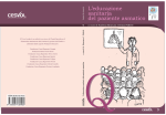
University of Bologna - Department of Mathematics
Piazza di Porta S.Donato, 5 - 40127 - Bologna
XCRayt:
the scene descriptor
User’s Guide - Version 2.0
G. Casciola
Department of Mathematics
University of Bologna
Bologna 2007
Abstract
This report describes the XCRayt and XCView packages. They are two
separate programs executable independently, but are to be considered part of
a single working instrument to phisically describe a geometrically modelled
scene in order to represent it realistically.
G. Casciola
Department of Mathematics, University of Bologna, P.zza di Porta S.Donato 5,
Bologna, Italy. E-mail: [email protected].
xcrayt User’s Guide . . .
Contents
Contents
1 What is XCRayt?
1.1 How to work with XCRayt . . . . . . . . .
1.1.1 Quit button . . . . . . . . . . . . .
1.1.2 Open button . . . . . . . . . . . .
1.1.3 New button . . . . . . . . . . . . .
1.2 Camera . . . . . . . . . . . . . . . . . . .
1.2.1 Control sector . . . . . . . . . . . .
1.2.2 Buttons sector . . . . . . . . . . .
1.3 Ambient . . . . . . . . . . . . . . . . . . .
1.3.1 Buttons sector . . . . . . . . . . .
1.4 Background . . . . . . . . . . . . . . . . .
1.4.1 Buttons sector . . . . . . . . . . .
1.5 Lights . . . . . . . . . . . . . . . . . . . .
1.5.1 Control sector . . . . . . . . . . . .
1.5.2 Buttons sector . . . . . . . . . . .
1.6 Objects . . . . . . . . . . . . . . . . . . .
1.6.1 Buttons sector . . . . . . . . . . .
1.6.2 Selector View sector . . . . . . . .
1.6.3 Transformation sector . . . . . . .
1.6.4 Texture space buttons . . . . . . .
1.7 Attributes . . . . . . . . . . . . . . . . . .
1.7.1 Buttons sector . . . . . . . . . . .
1.8 Other buttons in the Buttons sector . . .
1.8.1 Set and Undo buttons . . . . . . .
1.8.2 Reload, Save and Save As buttons
1.8.3 Delete button . . . . . . . . . . . .
1.8.4 Add button . . . . . . . . . . . . .
1.8.5 Render button . . . . . . . . . . .
1.8.6 Prefs button . . . . . . . . . . . .
1.9 Animation Control sector . . . . . . . . .
i
.
.
.
.
.
.
.
.
.
.
.
.
.
.
.
.
.
.
.
.
.
.
.
.
.
.
.
.
.
.
.
.
.
.
.
.
.
.
.
.
.
.
.
.
.
.
.
.
.
.
.
.
.
.
.
.
.
.
.
.
.
.
.
.
.
.
.
.
.
.
.
.
.
.
.
.
.
.
.
.
.
.
.
.
.
.
.
.
.
.
.
.
.
.
.
.
.
.
.
.
.
.
.
.
.
.
.
.
.
.
.
.
.
.
.
.
.
.
.
.
.
.
.
.
.
.
.
.
.
.
.
.
.
.
.
.
.
.
.
.
.
.
.
.
.
.
.
.
.
.
.
.
.
.
.
.
.
.
.
.
.
.
.
.
.
.
.
.
.
.
.
.
.
.
.
.
.
.
.
.
.
.
.
.
.
.
.
.
.
.
.
.
.
.
.
.
.
.
.
.
.
.
.
.
.
.
.
.
.
.
.
.
.
.
.
.
.
.
.
.
.
.
.
.
.
.
.
.
.
.
.
.
.
.
.
.
.
.
.
.
.
.
.
.
.
.
.
.
.
.
.
.
.
.
.
.
.
.
.
.
.
.
.
.
.
.
.
.
.
.
.
.
.
.
.
.
.
.
.
.
.
.
.
.
.
.
.
.
.
.
.
.
.
.
.
.
.
.
.
.
.
.
.
.
.
.
.
.
.
.
.
.
.
.
.
.
.
.
.
1
2
2
3
4
5
5
7
8
8
8
9
9
9
9
11
11
12
12
13
13
13
14
14
14
14
15
15
15
18
ii
LIST OF FIGURES
2 What is XCView?
19
2.1 Quit button . . . . . . . . . . . . . . . . . . . . . . . . . . . . 20
2.2 Open button . . . . . . . . . . . . . . . . . . . . . . . . . . . 20
2.3 Export button . . . . . . . . . . . . . . . . . . . . . . . . . . 21
3 Data file formats
3.1 Scene description . . .
3.2 View parameters . . .
3.3 Ray tracer parameters
3.4 Image file . . . . . . .
3.5 Standard image file . .
3.6 Animation file . . . . .
3.7 3d Animation file . . .
3.8 Statistics file . . . . .
.
.
.
.
.
.
.
.
.
.
.
.
.
.
.
.
.
.
.
.
.
.
.
.
.
.
.
.
.
.
.
.
.
.
.
.
.
.
.
.
.
.
.
.
.
.
.
.
.
.
.
.
.
.
.
.
.
.
.
.
.
.
.
.
.
.
.
.
.
.
.
.
.
.
.
.
.
.
.
.
.
.
.
.
.
.
.
.
.
.
.
.
.
.
.
.
.
.
.
.
.
.
.
.
.
.
.
.
.
.
.
.
.
.
.
.
.
.
.
.
.
.
.
.
.
.
.
.
.
.
.
.
.
.
.
.
.
.
.
.
.
.
.
.
.
.
.
.
.
.
.
.
.
.
.
.
.
.
.
.
.
.
.
.
.
.
.
.
.
.
.
.
.
.
.
.
23
23
25
25
26
26
26
27
27
List of Figures
29
Bibliography
31
xcrayt User’s Guide . . .
Chapter 1
What is XCRayt?
XCRayt is the scene desriptor of the XCModel system [XCMODEL00]. This
program is self-contained and executable from the XCModel console window.
It is distributed with the archive xcraytdev.tar.gz (development version)
and xcraytusr.tar.gz (executable version). Downloading and installation
instructions are in [XCMODEL00].
XCRayt is a system allowing a virtual scene to be described interactively, in
order to represent it realistically using the hrayt program. XCRayt could be
defined as the make-up room and film director’s office of a virtual film set.
The actors present on the set are the individual surfaces or objects (list of
surfaces) that have been modelled and/or put together using XCSurf (see
[XCSURF07]) and XCBool (see [XCBOOL00]). These surfaces are geometrically described by NURBS and trimmed NURBS surfaces, in parametric
form.
The costumes and make-up of the actors are defined by attributes of color
and the visual properties of the materials and/or by the application of texture.
The lighting for the set (or scenery) is divided into ”ambience” lighting,
background colour and properties and different types of puntiform light
sources.
The position of the actors on the set and the filming is respectively made
by the application of geometric transformations and the setting of the parameters of the camera.
Obviously, the system would be difficult to use for anyone not familiar
with 3D transformations and the parameters regulating them. Similarly,
some notions of optical physics, and of the lighting models used to simulate
realistic effects, are essential. For an introduction to these subjects see
[FOVD90] and [GLAS89].
However, the system is quite simple, so that even a user with little specific
knowledge can learn to use it by experimentation.
XCRayt is supported by a program, hrayt, that implements a ray tracing algorithm optimized for trimmed NURBS surfaces. This algorithm is
2
How to work with XCRayt
based on an algorithm of ray/surface intersection. The present version of
hrayt implements and gives the user the possibility to choose between three
different ray/surface intersection algorithms.
In order to run the program, no specific knowledge of these algorithms, or
of how a ray tracer works, is required. Obviously, a knowledge of how they
work, together with the possibility of setting many parameters, allows the
user to improve the performance in the rendering phase, sometimes even by
a few minutes. For an introduction to ray tracing see [GLAS89].
In spite of it is possible to describe a scene interactively from nothing, you
are advised about the possibility to create the entire scene graph using the
descriptor library (see [DESCR07]) and a script in C language. This scene
graph (saved as an .md file (see section 4.)) can be successively opened with
XCRayt, modified interactively, and rendered with the ray tracer.
1.1
How to work with XCRayt
When XCRayt is set up, it opens the window shown in fig.1.1. Note that
the GUI of XCRayt is made with xtools [XTOOLS00]. The work area is the
large window (its size is 1000 × 700) subdivided in six sectors that we call:
• Control (top left) that controls camera and lighting parameters;
• Object list (under the previous) from which it is possible to select
scene objects;
• Buttons (two rows of buttons at the bottom) which control a lot of
operations that we will see in detail;
• View (the large square area on the right) where the scene is visualised
in wire-frame;
• Selector View to select some usual view points;
• Transformation to control and management some object geometric
transformations in the scene and in the texture space (3D texturing).
As soon as this window appears, you will immediately see which actions are
possible. The buttons, cursors, textboxes, bars, etc. are accompanied by
one or more labels; for convention, if a label is drawn in black, the related
function is ’able’, whereas white means ’unable’. More labels near an xtools
object mean multifunctionality. Look now at the able buttons only.
1.1.1
Quit button
This button allows the user to quit XCRayt.
What is XCRayt?
3
Figure 1.1: XCRayt panel, before to load or create a scene
1.1.2
Open button
This button opens a control panel useful to open a scene graph or a
list of scene-graphs that we will call an animation (see Fig.1.2). In
this section we describes the Open Scene button; for the Animation
4
How to work with XCRayt
control buttons see section 1.9.
The Open Scene button opens a file request window to load a .md
Figure 1.2: Open/Animation Control panel
file, which describes a scene or project. From its directory site and
name, XCRayt deduces where to look for the scene components:
surfaces or objects are simple or trimmed NURBS surfaces or lists
of simple or trimmed NURBS surfaces. These are respectively
stored in files with .db, .dbe and .obj extensions. The file names
are included in the scene description file (.md) (see Data file formats section);
camera data consists of camera position, scene point, view-up, view
volume included in a .vw data file (it is looked for in the same
directory of the project);
rendering parameters consists of the parameters to define the ray
tracer execution included in a data file .arg (it is found in the
same project directory);
texture useful for texture mapping; consists of image files with .hr or
.ppm extensions.
The only essential file is the one that describes the scene (.md), while
the others (.arg e .vw) are optional and serve to provide a particular
rendering of the set. If you desire to load a .vw or .arg file, use the
correspondent buttons.
1.1.3
New button
This button opens a file request window that requires the name of the
directory to be used to contain the project. The camera, ambient and
background items with default values immediately appear in the box
object list and it is possible to begin to describe a scene interactively
from nothing.
What is XCRayt?
5
As soon as an .md file has been loaded, or if you have started to create
a scene, this is shown in the View sector under the default parameters of
camera and the object list is abled. It allows you to select any item in the
scene (see fig. 1.3). The hierarchical structure of the objects is shown by an
icon near to every item and, indented on the left, you will see its sub-items.
To select an item, click on it with the left mouse button. All and only the
functions regarding that item will then become active. Its relevant textbox,
as well as the bars, adds functionality enabling the user to select all the
objects. The associated textbox serves to select an object by name.
The following paragraphs describe all the functions provided according to
object type in the object list.
1.2
Camera
When selecting Camera in the Object list (this is the default selection that
appears with the Object list sector), all the functions relating to it are abled
in the XCRayt window (see fig 1.3). More precisely, the Control sector and
some of the buttons in the Buttons sector.
1.2.1
Control sector
The viewing direction is determined by the position of the camera and by
a scene point. As can be understood from the label, the left four arrows
(cursor) serves to position the camera, while the right serves to position the
scene point. These two parameters are reported numerically in the textboxes
below, from which they may also be varied. The X, Y and Z textboxes on
the right have a further function in helping the user to choose a scene point.
When they are pressed, a window appears (see fig. 1.4) allowing the center
of gravity of an object in the scene (surfaces or objects consisting of surfaces)
to be chosen as a scene point, or allowing the center of gravity co-ordinates
to be inserted. The buttons present in the Control sector serve to vary the
values of a fixed quantity (position, scene point and view volume).
Immediately below the cursors, next to the Distance label, there are two
buttons and a textbox. The latter provides the distance between camera
and scene point, while Near/Far moves the camera nearer to or further from
the scene point. In order to position the camera at a fixed distance, use the
textbox.
The Zoom button and the angle textbox allow the user to vary the view
volume. Also in this case, the buttons vary the angle by a certain step (see
Step button), while a precise value is inserted using angle textbox. If you
click on this textbox, a list of the most common objectives appears (see fig.
1.5) that are contained in the file camera.xclib which you will find in the
xcmodel/lib directory.
The data in the bottom left of the window, concerns the view up. The user
6
Camera
Figure 1.3: XCRayt panel, after a scene has been loaded
has not been allowed a general setting, because this would be of little interest in the rendering. Sometimes this is used to make the viewed object seem
rotated, while, in fact, it is the camera which is rotated. This parameter
is often (0,0,1), indicating a perfectly upright camera with respect to the
7
What is XCRayt?
Figure 1.4: Select a scene point (object point)
Figure 1.5: Select camera objective
vertical axis. The rotation buttons, next to the above, that only vary the
rotation of the frame (not the angle) are of greater utility.
Focus (Near/Far) has the same properties as Distance, except that it acts
on the scene point by moving it away from or towards the camera.
1.2.2
Buttons sector
Step button
This button opens a window (see fig. 1.6) enabling the user to vary the step
to modify the camera position, the scene point and the lights. The values
viewed are in degrees. In order to make the changes permanent, press the
8
Background
Figure 1.6: Step editor
Set button. The default values will always be reset every time that the
XCRayt program is run.
1.3
Ambient
If you select Ambient from the Object list, some buttons in the Buttons
sector will be abled.
1.3.1
Buttons sector
Figure 1.7: Ambient editor
Detail button
A window appears (see fig. 1.7) showing the present settings of the ambient
light and enabling the colour to be changed; this variation is interactive.
1.4
Background
If you select Background in the Object list, some buttons in the Buttons
sector will be abled.
9
What is XCRayt?
1.4.1
Buttons sector
Detail button
A window appears similar to the one in fig. 1.7 showing the present settings
of Background and enabling the colour to be changed and the background
to be reflecting or not.
1.5
Lights
If you select a light source in the Object list some functions in the Control
sector, and some buttons in the Buttons sector will be abled and the scene
will be viewed in the View sector according to the parameters set on the
light source.
1.5.1
Control sector
As can be seen on the label (see fig. 1.8), the left cursor is abled and determines the position of the light source, while the right cursor is unabled. The
Figure 1.8: Control sector
position is numerically reported in the textbox below, which can be altered.
Immediately beneath the active cursor, Distance is active, which moves the
light source nearer to or further from the scene point using Near/Far.
1.5.2
Buttons sector
Detail button
A window appears, shown in fig. 1.9, which contains a lot of information
about the lights: Type of light, color (Red, Green and Blue), Intensity,
etc. The type of light selected determines which elements of the GUI will
be active.
10
Objects
Figure 1.9: Light editor
• A Distant light is a light source at an infinite distance from the scene
on the direction defined by the (X, Y, Z) vector.
• A Point light is a light source in (X, Y, Z) with the intensity fading
linerly to zero at the distance defined by Max Range; if the Max
Range value is zero, the light intensity will not be dependent on the
distant travelled.
• A Warn light is a Point light with a direction in order to aim a light
at a particular area of an object. Conc. Exp defines the way in which
light intensity decreases away from the aim direction; a larger value
means that the light decreases quicker than for smaller value. Cone is
an angular value used to restrict the path of the light; it define a cone
surrounding the light direction. Flap On defines a plane equation
Ax + BY + CZ + D = 0; the half space containing the light respect
to the plane will be illuminated, while the other will not.
Step button
A window appears (see fig. 1.6) allowing the step changes of the camera
position, scene point and lighting to be modified. The values viewed are in
degrees. In order to make the changes permanent, press the Set button.
The default values will always be reset every time that the XCRayt program
is run.
11
What is XCRayt?
1.6
Objects
If an object item or one of its subitems in the Object list has been selected,
some buttons in the Buttons, Selector View and Transformation sectors will
be abled, and the scene will be viewed in the View sector from the point
of view of the camera, showing the selected object (which will be drawn in
white).
1.6.1
Buttons sector
Figure 1.10: Link attribute to object
Detail button
This function allows you to match the selected object with a material. The
materials to be used must already have been defined (see Attributes in the
next section). Fig. 1.10 shows how to carry out this operation. The object
will always be defined in a particular material, which, if unspecified, will be
the default. The (unmodifiable) data concerning this material is provided
in two sections according to type: at the top, if it is an attribute, at the
bottom, if it is a texture. If the selected object is not a leaf (a surface) in
the hierarchy, it is not possible to identify the material from which it has
been made (this is only possible by checking the leaves or the surfaces).
If you choose a texture, only some of the GUI fields will be abled (according
to type). With texture mapping it is possible to choose and load an image
from the texture directory through a file request; the image will be copied
12
Objects
into the project directory and viewed in the square in the bottom left of the
screen (see fig.1.10)(not yet implemented).
1.6.2
Selector View sector
This sector consists of 5 checkpoints (see fig.1.3); their selection allows a
special scene to be viewed, or rather, a selected object in the scene to be
viewed. The 5 views are:
• Perspective
• Front
• Side
• Up
• Quad
The Perspective view is the default. In each of these, the selected object will
appear drawn in white, to be shown in the scene. The Quad view consists
in the subdivision of the View sector into four parts showing the previous
views.
1.6.3
Transformation sector
If an object item or one of its subitems in the Object list has been selected,
the Transformation sector will be abled; this allows to modifies in terms
of position (translation), scaling, rotation and share the selected object’s
geometry. Numerical and interactive transformations using respectively the
Keyboard and Mouse buttons are possible. In the Numerical case, before to execute the transformation by pressing the Keyboard button, some
numerical values have to be setted. More precisely for each single transformation, the user has to provide the fixed point. Information about the
center of gravity (Baricenter) of the selected object, which will be assumed
to be as before, unless specified, will help the user to do this. According to
the chosen transformation (through the checkpoints) the user will be asked
to insert the following parameters: the degree of rotation, the new position,
the scaling factor, the shear factors, etc. For the scaling it is possible to
obtain a modification by varying the percentage of the different dimensions.
In the Interactive case, press the Mouse button and then use the mouse,
according to the chosen transformation (through the checkpoints), in the
View sector to set the transformation actions.
13
What is XCRayt?
1.6.4
Texture space buttons
These buttons allow the selected object, in the Object list, to be applied a
texture image or to be put in a texture 3D space.
Pressing the Modify button, the ”object transformation in the texture
space” mode, will be abled; a red cube which virtually represents the 3d
texture space is shown; the next transformations on the object will be interpreted as transformations of the object with respect to the texture space.
To go out of this mode press the Done button. A matrix of texture transformation, which will be applied in rendering phase, remains defined.
1.7
Attributes
If you select an attribute in the Object list, some buttons in the Buttons
sector will be abled.
1.7.1
Buttons sector
Figure 1.11: Attribute editor
Detail button
The window shown in fig. 1.11 appears, enabling the parameters for the
selected attribute to be defined. These are the materials that can be associated with the objects in the scene; the refraction indexes are very important
for their definition. By pressing the textbox relating to a Refraction Index
the user can able a selection window containing a list of the most common
materials. However, it is always possible to insert a generic material. Also in
this case a library file has been created (refractionindex.xclib nella directory
14
Other buttons in the Buttons sector
xcmodel/lib) in ASCII format, which can be edited by the user. For more
information about the parameters defining an attribute see [DESCR07].
1.8
1.8.1
Other buttons in the Buttons sector
Set and Undo buttons
The pair of buttons Set e Undo allow a minimum level of undo/redo to be
made on every object. These are immediately enabled, as soon as an object
has been modified. The first shows the wish to make the changes permanent
in the scene (in the memory but not on the file), while the second replaces
the previous values in the object. If Set is chosen, both this button and
Undo will be unabled and the buttons Save and Save As will appear.
The Undo button is also useful to undo a transformation done using the
Transformation sector.
1.8.2
Reload, Save and Save As buttons
The Reload button allows the whole project to be reloaded without having
to reopen file request again to repeat the selection. This is useful in cases
in which the scene has been recompiled using the descriptor library, or you
wish to start again from the last changes saved.
The Save As button is used to save the project on files; the model is saved
in a file with an .md extension and the viewing parameters in a file with
an .vw extension. It is possible to save one or both (see fig.1.12), and it is
possible to choose an appropriate filename or directory. The Save button
Figure 1.12: Save As files
saves automatically both .md and .vw file with the chosen name and project
directory.
1.8.3
Delete button
This option deletes an element from the scene, the one selected in the object list. It is not possible to delete Camera, Ambient or Background. If
What is XCRayt?
15
these are superfluous for a particular project, can be unabled by setting the
intensity to zero, or by setting them as though they were black. As far as
the other elements are concerned, the selected object will be deleted. In the
case of the attributes it is not possible to delete an attribute of an object
that is still being used. First you need to delete the object (or objects) that
refer to it, or change its reference points. As far as hierarchy is concerned,
this is a more difficult problem, since the data structure is tree-like. The
user must be particularly careful when deleting the final ”leaf” of a ”node”.
In this case, the ”node” will also have to be deleted to produce a new tree
(not yet implemented).
The Delete operation is permanent, there is no Undo.
1.8.4
Add button
This option adds lights, attributes or objects. No other type of insertion
is possible. For the first two, once a name has been chosen, the windows
already viewed in fig. 1.9 and fig. 1.11 will be opened with their default
values (standard attribute and white Warn light). This new attribute or
light will appear at the bottom of the attributes and lights list. The objects
behave differently. In fact, they have several types of insertion:
surface add a simple surface (file .db or dbe) in the tree ;
object add an object (list of surfaces included in a file .obj);
copy of a leaf add a simple surface already presented in the hierarchy as
a leaf;
copy of a subtree add an object already presented in the hierarchy as a
subtree;
1.8.5
Render button
This button executes the rendering engine. If it comes across a change in
the project that has not yet been saved, the user will be asked to save the
project; xhrayt will only run when the user has saved all the modifications.
The window shown in fig.1.13 (front-end image of hrayt) is opened by xhrayt
program, which then runs hrayt, the real ray-tracer of XCModel; the bar
shows the progress of the rendering. The system allows several types of
rendering to be executed.
1.8.6
Prefs button
This button allows a series of parameters defining the ways in which the ray
tracer must render the model to be varied interactively throught the window
16
Other buttons in the Buttons sector
Figure 1.13: xhrayt execution
of fig. 1.14.
The parameters contained when the window is opened are readden by a file
Figure 1.14: Render parameters
with the same name as the project and with an .arg extension. If these files
What is XCRayt?
17
do not exist, the default parameters will be used. It is possible to load an
.arg file with a different name from that of the project by setting the name
and using the Load button. The parameters are:
• Image Size to set the dimensions of the image to be produced. The
information consists in the number of lines and columns of the discretised grid of the screen in pixels or in the number of lines or pixels for
a square grid.
• Seads Subdivision (Scene) and Seads Subdivision (Obj) to determine the number of divisions along each axis, in order to subdivide
the scene space and the NURBS objects. The three-dimensional grids
are represented by a SEADS data structure, which stands for Spatially
Enumerated Auxiliary Data Structure.
• Bezier Subdivision Level to determine the subdivision level of the
parametric space of each surface, as well as the basic one in Bezier
patches. Each of these patches is then evenly subdivided into 2k
patches, where k is the value of the object field.
• Ray Depth Level sets the maximum depth of the ray tree.
• Surface Flatness defines the tolerance with which a surface is considered flat in the Bezier subdivision process..
• Min. Intensity Contribute defines the value below which the contribution coming from a ray on the ray tree should not be considered.
• Depth-cueing Distance sets the maximum distance a surface point
is viewed and then rendered.
• Light Models determines the lighting model on which to base the
rendering of the scene.
• Intersector determines the type of algorithm intersector used by the
ray tracer.
• Shadows Effect allows shadows to be enabled.
• Shadows Ray Cache allows caching of shadows to be improved.
• Statistics Report enables the production of a file containing statistical data about the execution of the ray tracer.
• Statistics file and Output file specify the names of the related files.
The buttons Set and Cancel respectively enable the new parameters or
return to the previous ones. The Save button saves the parameters set in
the specified .arg file. The Default button sets the default parameters.
18
Animation Control sector
1.9
Animation Control sector
Pressing the Open button in XCRayt (see fig. 1.1) opens a control panel
useful to control little animations by the Animation Control sector (see
Fig.1.2). Producing little animations starting from a scene-graph or loading
and modifying an animation previously created (.ani file) by executing a C
language code which make use of the descriptor library, is possible. In case
of generation from a scene-graph, after loading one by the Open Scene
button, use the Save button in the Animation Control sector to save a .ani
file made, at this moment, from a single frame. Now through the > button, producing new frames as copy of the initial one, is possible; modifying
these copies of the scene-graph and saving the modifications by the Rec
button allows to produce a little 3d animation. In case of loading an animation previously created, use the Load .ani button. As before, through
the buttons >, <<, < and >>, running the frame and introducing possible
modifications is possible. The buttons present in this panel are:
• Load .ani: allows to load an animation previously saved which consists
in a list of scene-graphs;
• Rec: saves the changes made on the current scene-graph and joins it
to a frame;
• Del: deletes the current scene-graph and then the correspondent frame;
• Ins: inserts a scene-graph after the current one (and then a frame)
creating a copy;
• Save as: saves with a name the 3d animation or the scene-graph list;
• Save: saves with the current name the 3d animation or the scene-graph
list;
• Render: renders all the scene-graphs and creates a .hra file.
xcrayt User’s Guide . . .
Chapter 2
What is XCView?
XCView is the viewer of the XCModel system [XCMODEL00]. It is selfcontained and executable from the XCModel console window. It is distributed with the archive xcraytdev.tar.gz (development version) and xcraytusr.tar.gz (executable version). Downloading and installation instructions
are in [XCMODEL00].
XCView is a viewer for images produced by XCRayt (or rather, by hrayt).
It is therefore useful to view images that have previously been produced and
saved, but, above all, to view animations made using XCRayt, which have
been saved, photogram by photogram, but not viewed.
XCView also allows the image format of XCModel, that is .hr to be converted
into a standard format, such as ppm.
It can be executed from the console window of XCModel. XCView appears with the window of fig. 2.1, which has the functions described below.
Figure 2.1: XCView control panel
20
2.1
Export button
Quit button
This button allows the user to quit XCView.
2.2
Open button
This button opens a file request to load a .hr or .ppm image file, or a file
.hra containing a list of images. If an image file has been selected, it will
be viewed as follows (see fig. 2.2). This image file can then be saved again
using the Save As button with a different name and/or format (from .hr
to .ppm or viceversa). If a list of images is selected (.hra file), these will
all be loaded in the memory and the sector of the window that manages
the animations will be enabled. Using the Rew, Play and Fwd buttons
it is possible, respectively, to rewind the film photogram by photogram, to
view the whole animation at the speed chosen by the Speed bar, and to go
through the animation photogram by photogram. Rewind and Forward
can also be performed using the Frame bar. In this case the Save As
button is unabled while the Export button is enabled.
Figure 2.2: Rendered image
21
What is XCView?
2.3
Export button
This button allows to export an animation previously produced and loaded
as .hra file in an animated gif (.gif) file. To the pressure of the Export
button it opens the file request in which the name of the file with which one
wants to export the animation has to be given; a panel which will allow to
select a few parameters will be opened (see fig. 2.3):
• transparency colour: pixels which have the same selected colour will
be given back in a transparent way; this is useful in an image composition and in particular to present an animated object on a background
image, how often happens in realizing a web page;
• delay: the delay in terms of second between the various frame;
• cyclic animation: makes a cycle of frame to have an infinite animation
or not.
Figure 2.3: Export a gif file
xcrayt User’s Guide . . .
Chapter 3
Data file formats
In this section the syntax of each file format used by XCRayt is given
and explained. The data files created or used by XCRayt are stored in
xcmodel/models directory as default. The # character in the following is a
comment to the data in the file.
3.1
Scene description
The following example file is xcmodel/models/gc chess/gc chess.md.
gc chess is the directory project, gc chess.md is the scene graph file. The
extension .md identifies a scene model. The format is self-explanatory.
HEADER: torre 3 3 1 #scene name,N.lights,N.attrs+1,N.file surf
AMBIENT COLOR: 1.000000e+00 1.000000e+00 1.000000e+00 #ambient
AMBIENT INTENSITY: 7.000000e-01
# ambient
BKG COLOR: 4.470000e-01 4.700000e-01 5.880000e-01 #background
BKG IS REFL: 0
#background
LIGHT N. 0
# defines the first light of three
NAME: distant_light
# light name
TYPE: 0
LOCATION: 0.000000e+00 0.000000e+00 0.000000e+00
DIRECTION: 0.000000e+00 0.000000e+00 1.000000e+00
COLOR: 1.000000e+00 1.000000e+00 1.000000e+00
INTENSITY: 7.000000e-01
CONCENTRATION: 0
MAX RANGE: 0.000000e+00
CONE: -1.000000e+00
FLAP: 0 0.000000e+00 0.000000e+00 0.000000e+00 0.000000e+00
LIGHT N. 1
# defines the second light of three
NAME: point_light
# light name
...
24
Scene description
ATTRIBUTES N. 1
# defines the first attr. of two
NAME: scacco_bianco
# attribute name
COLOR: 4.820000e-01 4.820000e-01 1.000000e+00
# RGB values
5.000000e-01
# ambient reflection
5.000000e-01
# diffuse reflection
4.000000e-01
# mirror reflection
INDEX: 1.000000e+00 1.000000e+00
# refraction index
2
# Phong’s exponent
0.000000e+00 0.000000e+00
# Min. and Max. transparency
0
# transparency power
ATTRIBUTES N. 2
# defines the second attr. of two
...
SURFACE N. 0
# defines the first surface. of one
NAME: Qtorre.db
# surface name
IS SURFACE: 1
NORMAL INSIDE: 0
# surface normal versus
EXTENT:
# surface bounding box
0.000000e+00 0.000000e+00 0.000000e+00
2.000000e-01 2.000000e-01 6.400000e-01
HIERARCHY:
# begin the hierarchy description
OBJECT TYPE: 1
# root
OBJECT NAME: torre
# root name
OBJECT TYPE: 3
# a left leaf
PRIMITIVE NAME: slice_4
# left leaf surface name
GEO SHAPE: 11
# surface geometric transform. to apply
TRANSFORM MATRIX TYPE: 1
TRANSFORM MATRIX:
-4.846628e-15 -1.000000e+00 0.000000e+00
1.000000e+00 -4.846628e-15 0.000000e+00
0.000000e+00 0.000000e+00 1.000000e+00
2.500000e-01 1.750000e+00 0.000000e+00
16
0
TEXTURE MATRIX TYPE: 1
#surf. material (texture and attr.)
TEXTURE MATRIX:
-1.864088e-14 -3.846154e+00 0.000000e+00
3.846154e+00 -1.864088e-14 0.000000e+00
0.000000e+00 0.000000e+00 1.000000e+00
0.000000e+00 0.000000e+00 0.000000e+00
TEXTURE DATA SIZE = 1
TEXTURE DATA TYPE: 3
0 0
0 0
2.352941e-03 3.137255e-03
25
Data file formats
0.000000e+00 0.000000e+00 0.000000e+00 0.000000e+00
marble_5_black.hr
# texture file
ATTRIBUTE N. 2
# attribute applied
NURBS N. 0
# index NURBS surface loaded
OBJECT TYPE: 2
# a right son (node tree)
OBJECT TYPE: 3
# a left leaf
PRIMITIVE NAME: slice_3
# left leaf surface name
...
OBJECT TYPE: 2
# right son
OBJECT TYPE: 3
# a left leaf
PRIMITIVE NAME: slice_2
#left leaf surface name
...
OBJECT TYPE: 2
# right son
OBJECT TYPE: 3
# a left leaf
PRIMITIVE NAME: slice_1
# left leaf surface name
...
OBJECT TYPE: 0
# a right leaf
3.2
View parameters
Contains the necessary information in order to define a 3D perspective view,
that can simulate filming with a telecamera. These files have an .vw extension.
14.03 11.72 1.60
0.20 0.80 0.45
-0.00 -0.09 0.99
26.00
1.00
3.3
# camera point
# scene point or object point
# view up
# view volume
# aspect ratio x/y
Ray tracer parameters
These parameters define the arguments of the ray tracer. These files have
an .arg extension.
11
-L200
-e0.004000
-w
-c
-v1
-n1
-B1.000000
# number of arguments, follows the arg list
26
Animation file
-S gc_chess.sta
-o gc_chess.hr
The arguments can be:
argument
signify
-B n
min flat ratio
-b
Blinn light model
-c
no shadow cache
-Dn
max 2n subdivision in Bezier patches
-ddepth
max intersection tree depth
-ex
minimum intensity contribution
-Ln
image resolution
-ln
first line to be processed
-MB
Bezier Clipping intersector method
-MT
Toth intersector method
-nn
nurbs extent subdivisions
-o filename
image filename
-Pn
number of width pixels in the image; the height is
deduced by the aspect ratio
-pn
first pixel to be processed
-rreach
computed intensity is proportional to the distance
between the camera and the point considered. This
is linearly scaled by a factor one at zero distance to
a factor zero at the reach distance
-S filename
statistical file name
-s
shadow ON
-vn
scene extent subdivisions
-w
Whitted light model
3.4
Image file
This is a compressed, non-standard format for images, which can also be
used for textures. These files have an .hr extension.
3.5
Standard image file
Standard image format common in Xwindow environments and known as
ppm. This is a binary RGB file for true-color images.
3.6
Animation file
This contains the list, in ASCII format, of the frames (.hr or .ppm files)
making up the animation (.hra file).
27
Data file formats
10
frame1.hr
frame2.hr
....
frame9.hr
frame10.hr
3.7
# frame number
# follows the frames file names
3d Animation file
This contains the list, in ASCII format, of the scene-graphs (.md, .vw and
.arg files) making up the 3d animation (.ani file).
scacchi.ani
20
0
scacchi0.md
1
scacchi1.md
2
scacchi2.md
....
19
scacchi19.md
20
scacchi20.md
3.8
scacchi.vw
scacchi.vw
scacchi.vw
# the file name
# scene-graph number
scacchi.arg # follows the scene-graphs...
scacchi.arg # ...file names
scacchi.arg
scacchi.vw
scacchi.vw
scacchi.arg
scacchi.arg
Statistics file
Statistics file for the image. This contains information about image generation. It is generated from XCRayt only if requested and, if it already exists,
the information relating to the image in the rendering phase will be appended to the file. As an example, here is the Statistics file of the rendering
of a scene.
GENERAL STATISTICS
-----------------run-length-encoded image on ............
../models/gc_chess/gc_chess.hr
image resolution (lines x pixels) ......
maximum intersection-tree depth ........
adaptive intersection-tree depth control
minimum intensity contribution .........
lighting model .........................
depth cueing range .....................
shadows ................................
shadows cache ..........................
number of light sources ................
number of primitive objects ............
:
:
:
:
:
:
:
:
:
:
:
200x200
1
ON
0.004
Whitted
0.0 - INFINITY
OFF
OFF
3
4
28
number of textured primitives ..........
total number of patches ................
max uniform subdivision depth ..........
min patch flatness .....................
Statistics file
:
:
:
:
number of rays traced .....................
total number of ray-extent checks .........
number of ray-object intersections ........
number of shadow ray-object intersections .
4
31
0
1.00%
:
:
:
:
38000
1710148
11463 (30.17%)
0 (NaN%)
number of ray-patch intersections calls .... : 79600
number of tests resolved with second extent : 19786 (24.86%)
Seads statistics : Scene seads
------------------------------------------------------------object tested per ray ......................... : 1.83
box tested per ray ............................ : 4.00
object tested per normal ray .................. : 1.83
object tested per shadow ray .................. : NaN
box tested per normal ray ..................... : 4.00
box tested per shadow ray ..................... : NaN
percentage empty voxel ........................ : 0.00%
average objects per noempty voxel ............. : 4.00
------------------------------------------------------------Seads statistics : Second level
------------------------------------------------------------object tested per ray ......................... : 1.75
box tested per ray ............................ : 31.00
object tested per normal ray .................. : 1.75
object tested per shadow ray .................. : NaN
box tested per normal ray ..................... : 31.00
box tested per shadow ray ..................... : NaN
percentage empty voxel ........................ : 0.00%
average objects per noempty voxel ............. : 31.00
-------------------------------------------------------------
preprocessing time ..................... :
ray tracing processing time ............ :
total processing time .................. :
0h
0h
0h
0’
0’
0’
0.00’’
12.00’’
12.00’’
xcrayt User’s Guide . . .
List of Figures
1.1
1.2
1.3
1.4
1.5
1.6
1.7
1.8
1.9
1.10
1.11
1.12
1.13
1.14
XCRayt panel, before to load or create a scene
Open/Animation Control panel . . . . . . . . .
XCRayt panel, after a scene has been loaded . .
Select a scene point (object point) . . . . . . .
Select camera objective . . . . . . . . . . . . .
Step editor . . . . . . . . . . . . . . . . . . . .
Ambient editor . . . . . . . . . . . . . . . . . .
Control sector . . . . . . . . . . . . . . . . . . .
Light editor . . . . . . . . . . . . . . . . . . . .
Link attribute to object . . . . . . . . . . . . .
Attribute editor . . . . . . . . . . . . . . . . . .
Save As files . . . . . . . . . . . . . . . . . . . .
xhrayt execution . . . . . . . . . . . . . . . . .
Render parameters . . . . . . . . . . . . . . . .
.
.
.
.
.
.
.
.
.
.
.
.
.
.
.
.
.
.
.
.
.
.
.
.
.
.
.
.
.
.
.
.
.
.
.
.
.
.
.
.
.
.
.
.
.
.
.
.
.
.
.
.
.
.
.
.
.
.
.
.
.
.
.
.
.
.
.
.
.
.
.
.
.
.
.
.
.
.
.
.
.
.
.
.
.
.
.
.
.
.
.
.
.
.
.
.
.
.
.
.
.
.
.
.
.
.
.
.
.
.
.
.
3
4
6
7
7
8
8
9
10
11
13
14
16
16
2.1
2.2
2.3
XCView control panel . . . . . . . . . . . . . . . . . . . . . .
Rendered image . . . . . . . . . . . . . . . . . . . . . . . . . .
Export a gif file . . . . . . . . . . . . . . . . . . . . . . . . . .
19
20
21
xcrayt User’s Guide . . .
Bibliography
[XCMODEL00] G.Casciola, xcmodel: a system to model and render NURBS
curves and surfaces; User’s Guide - Version 1.0, Progetto MURST:
”Analisi Numerica: Metodi e Software Matematico”, Ferrara (2000),
http://www.dm.unibo.it/∼casciola/html/xcmodel.html
[XCSURF07] G.Casciola, xcsurf: the 3D modeller; User’s Guide - Version4.0
http://www.dm.unibo.it/∼casciola/html/xcmodel.html
[XCBOOL00] G.Casciola, xcbool: the object composer; User’s Guide - Version 1.0, Progetto MURST: ”Analisi Numerica: Metodi e Software
Matematico”, Ferrara (2000),
http://www.dm.unibo.it/∼casciola/html/xcmodel.html
[XTOOLS00] S.Bonetti, G.Casciola, xtools library; Programming Guide Version 2.0, (2000)
http://www.dm.unibo.it/∼casciola/html/xcmodel.html
[DESCR07] G.Casciola, descriptor library; Programming Guide - Version
3.0, (2007)
http://www.dm.unibo.it/∼casciola/html/xcmodel.html
[FOVD90] J.D.Foley, A.VanDam, S.K.Feiner, J.F.Hughes, Computer
Graphics principles and practice, II Edition, Addison Wesley (1990).
[GLAS89] A.S.Glassner, An introduction to ray tracing, Academic Press
(1989).