1
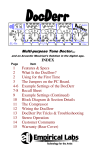
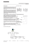
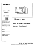
Website: http://biz.lgservice.com
MICROWAVE OVEN
SERVICE MANUAL
MODEL: MH-1355M
MH-1356M
MH-1357M
CAUTION
BEFORE SERVICING THE UNIT, READ THE SAFETY PRECAUTIONS IN THIS MANUAL.
P/NO : 3828W5S6174
July, 1998
Printed in Korea
SAFETY PRECAUTIONS
This device is to be serviced only by properly qualified service personnel.
Consult the Service Manual for proper service procedures to assure continued safety operation and for
precautions to be taken to avoid possible exposure to excessive microwave energy.
PRECAUTIONS TO BE OBSERVED BEFORE
AND DURING SERVICING TO AVOID POSSIBLE
EXPOSURE TO EXCESSIVE MICROWAVE
ENERGY
A) Do not operate or allow the oven to be operated with the door open.
B) Make the following safety checks on all ovens to be serviced before activating the magnetron
or other microwave source, and make repairs as necessary; (1) interlock operation, (2) proper
door closing, (3) seal and sealing surfaces (arcing, wear, and other damage), (4) damage to or
loosening of hinges and latches, (5) evidence of dropping or abuse.
C) Before turning on microwave power for any service test or inspection within the microwave
generating compartments, check the magnetron, wave guide or transmission line, and cavity
for proper alignment, integrity, and connections.
D) Any defective or misadjusted components in the interlock, monitor, door seal, and microwave
generation and transmission systems shall be repaired, replaced, or adjusted by procedures
described in this manual before the oven is released to the owner.
E) A microwave leakage check to verify compliance with the Federal Performance Standard
should be performed on each oven prior to release to the owner.
— Proper operation of the microwave ovens requires that the magnetron be assembled to the wave guide and
cavity. Never operate the magnetron unless it is properly installed.
— Be sure that the magnetron gasket is properly installed around the dome of the tube whenever installing the
magnetron.
— Routine service safety procedures should be exercised at all times.
— Untrained personnel should not attempt service without a thorough review of the test procedures and safety
information contained in this manual.
–2–
TABLE OF CONTENTS
SPECIFICATIONS - - - - - - - - - - - - - - - - - - - - - - - - - - - - - - - - - - - - - - - - - - - - - - - - - - - - - - - - - - - - - - - - - - - - - - - - - - - - - - - - - - - - - - - - - - - - - - - - - - - - - - - - - - - - - - - - - - - - - - - 4
CAUTIONS - - - - - - - - - - - - - - - - - - - - - - - - - - - - - - - - - - - - - - - - - - - - - - - - - - - - - - - - - - - - - - - - - - - - - - - - - - - - - - - - - - - - - - - - - - - - - - - - - - - - - - - - - - - - - - - - - - - - - - - - - - - - - - - - - 5
INSTALLATIONS - - - - - - - - - - - - - - - - - - - - - - - - - - - - - - - - - - - - - - - - - - - - - - - - - - - - - - - - - - - - - - - - - - - - - - - - - - - - - - - - - - - - - - - - - - - - - - - - - - - - - - - - - - - - - - - - - - - - - - - - - 6
FEATURE DIAGRAM - - - - - - - - - - - - - - - - - - - - - - - - - - - - - - - - - - - - - - - - - - - - - - - - - - - - - - - - - - - - - - - - - - - - - - - - - - - - - - - - - - - - - - - - - - - - - - - - - - - - - - - - - - - - - - - - - - - 7
CONTROL PANEL - - - - - - - - - - - - - - - - - - - - - - - - - - - - - - - - - - - - - - - - - - - - - - - - - - - - - - - - - - - - - - - - - - - - - - - - - - - - - - - - - - - - - - - - - - - - - - - - - - - - - - - - - - - - - - - - - - - - - - - 8
HOW THE MICROWAVE/CONVECTION OVEN WORKS - - - - - - - - - - - - - - - - - - - - - - - - - - - - - - - - - - - - - - - - - - - - - - - - - - - - - - - - - - - - - - - - - 10
COOKING FLOW CHART - - - - - - - - - - - - - - - - - - - - - - - - - - - - - - - - - - - - - - - - - - - - - - - - - - - - - - - - - - - - - - - - - - - - - - - - - - - - - - - - - - - - - - - - - - - - - - - - - - - - - - - - - - - 11
OPERATING INSTRUCTIONS - - - - - - - - - - - - - - - - - - - - - - - - - - - - - - - - - - - - - - - - - - - - - - - - - - - - - - - - - - - - - - - - - - - - - - - - - - - - - - - - - - - - - - - - - - - - - - - - - - - - - 12
SCHEMATIC DIAGRAM - - - - - - - - - - - - - - - - - - - - - - - - - - - - - - - - - - - - - - - - - - - - - - - - - - - - - - - - - - - - - - - - - - - - - - - - - - - - - - - - - - - - - - - - - - - - - - - - - - - - - - - - - - - - - 15
CIRCUIT DESCRIPTION - - - - - - - - - - - - - - - - - - - - - - - - - - - - - - - - - - - - - - - - - - - - - - - - - - - - - - - - - - - - - - - - - - - - - - - - - - - - - - - - - - - - - - - - - - - - - - - - - - - - - - - - - - - - - 18
DESCRIPTION AND FUNCTION OF COMPONENTS - - - - - - - - - - - - - - - - - - - - - - - - - - - - - - - - - - - - - - - - - - - - - - - - - - - - - - - - - - - - - - - - - - - - - 20
NECESSARY TOOLS AND MEASURING INSTRUMENTS - - - - - - - - - - - - - - - - - - - - - - - - - - - - - - - - - - - - - - - - - - - - - - - - - - - - - - - - - - - - - - 22
INSTALLATION AND ADJUSTMENT OF THE INTERLOCK SYSTEM - - - - - - - - - - - - - - - - - - - - - - - - - - - - - - - - - - - - - - - - - - - - - - 23
INTERLOCK CONTINUITY TEST - - - - - - - - - - - - - - - - - - - - - - - - - - - - - - - - - - - - - - - - - - - - - - - - - - - - - - - - - - - - - - - - - - - - - - - - - - - - - - - - - - - - - - - - - - - - - - - - - 25
DISASSEMBLY AND PARTS REPLACEMENT PROCEDURE - - - - - - - - - - - - - - - - - - - - - - - - - - - - - - - - - - - - - - - - - - - - - - - - - - - - - - - - - 26
TROUBLESHOOTING - - - - - - - - - - - - - - - - - - - - - - - - - - - - - - - - - - - - - - - - - - - - - - - - - - - - - - - - - - - - - - - - - - - - - - - - - - - - - - - - - - - - - - - - - - - - - - - - - - - - - - - - - - - - - - - - 30
COMPONENT TEST PROCEDURE - - - - - - - - - - - - - - - - - - - - - - - - - - - - - - - - - - - - - - - - - - - - - - - - - - - - - - - - - - - - - - - - - - - - - - - - - - - - - - - - - - - - - - - - - - - - - - 36
PROCEDURE FOR MEASURING MICROWAVE ENERGY LEAKAGE - - - - - - - - - - - - - - - - - - - - - - - - - - - - - - - - - - - - - - - - - - - - - - 42
EXPLODED VIEW AND PARTS LIST - - - - - - - - - - - - - - - - - - - - - - - - - - - - - - - - - - - - - - - - - - - - - - - - - - - - - - - - - - - - - - - - - - - - - - - - - - - - - - - - - - - - - - - - - - - 44
INTRODUCTION - - - - - - - - - - - - - - - - - - - - - - - - - - - - - - - - - - - - - - - - - - - - - - - - - - - - - - - - - - - - - - - - - - - - - - - - - - - - - - - - - - - - - - - - - - - - - - - - - - - - - - - - - - - - - - - - - - - 44
1. DOOR PARTS - - - - - - - - - - - - - - - - - - - - - - - - - - - - - - - - - - - - - - - - - - - - - - - - - - - - - - - - - - - - - - - - - - - - - - - - - - - - - - - - - - - - - - - - - - - - - - - - - - - - - - - - - - - - - - - - - 45
2. CONTROL PANEL PARTS - - - - - - - - - - - - - - - - - - - - - - - - - - - - - - - - - - - - - - - - - - - - - - - - - - - - - - - - - - - - - - - - - - - - - - - - - - - - - - - - - - - - - - - - - - - - - - - - 46
3. OVEN CAVITY PARTS - - - - - - - - - - - - - - - - - - - - - - - - - - - - - - - - - - - - - - - - - - - - - - - - - - - - - - - - - - - - - - - - - - - - - - - - - - - - - - - - - - - - - - - - - - - - - - - - - - - - - - 47
4. OVEN INTERIOR PARTS (1) - - - - - - - - - - - - - - - - - - - - - - - - - - - - - - - - - - - - - - - - - - - - - - - - - - - - - - - - - - - - - - - - - - - - - - - - - - - - - - - - - - - - - - - - - - - - - 48
5. OVEN INTERIOR PARTS (2) - - - - - - - - - - - - - - - - - - - - - - - - - - - - - - - - - - - - - - - - - - - - - - - - - - - - - - - - - - - - - - - - - - - - - - - - - - - - - - - - - - - - - - - - - - - - - - 49
6. LATCH PARTS - - - - - - - - - - - - - - - - - - - - - - - - - - - - - - - - - - - - - - - - - - - - - - - - - - - - - - - - - - - - - - - - - - - - - - - - - - - - - - - - - - - - - - - - - - - - - - - - - - - - - - - - - - - - - - - - 50
7. BASE PLATE PARTS - - - - - - - - - - - - - - - - - - - - - - - - - - - - - - - - - - - - - - - - - - - - - - - - - - - - - - - - - - - - - - - - - - - - - - - - - - - - - - - - - - - - - - - - - - - - - - - - - - - - - - - 51
8. WIRING HARNESS PARTS - - - - - - - - - - - - - - - - - - - - - - - - - - - - - - - - - - - - - - - - - - - - - - - - - - - - - - - - - - - - - - - - - - - - - - - - - - - - - - - - - - - - - - - - - - - - - - - 52
9. CIRCUIT BOARD - - - - - - - - - - - - - - - - - - - - - - - - - - - - - - - - - - - - - - - - - - - - - - - - - - - - - - - - - - - - - - - - - - - - - - - - - - - - - - - - - - - - - - - - - - - - - - - - - - - - - - - - - - - - - 53
10. CIRCUIT BOARD SCHEMATIC DIAGRAM - - - - - - - - - - - - - - - - - - - - - - - - - - - - - - - - - - - - - - - - - - - - - - - - - - - - - - - - - - - - - - - - - - - - - - - - - 54
REPLACEMENT PARTS LIST - - - - - - - - - - - - - - - - - - - - - - - - - - - - - - - - - - - - - - - - - - - - - - - - - - - - - - - - - - - - - - - - - - - - - - - - - - - - - - - - - - - - - - - - - - - - - - - - - 55
–3–
SPECIFICATIONS
Power Supply - - - - - - - - - - - - - - - - - - - - - - - - - - - - - - - - - - - - - - - - - - - - - - - - - - - 120 VAC, 60 Hz
Power Consumption - - - - - - - - - - - - - - - - - - - - - - - - - - - - - - - - - - - - - - - - - - 1400 Watts (Microwave), 12A
1580 Watts (Convection), 13.2A
Output - - - - - - - - - - - - - - - - - - - - - - - - - - - - - - - - - - - - - - - - - - - - - - - - - - - - - - - - - - - - - - *850 Watts (Microwave)
1500 Watts (Convection)
Microwave Frequency - - - - - - - - - - - - - - - - - - - - - - - - - - - - - - - - - - - - - - - 2450 MHz ± 50 MHz
High Voltage Capacitor - - - - - - - - - - - - - - - - - - - - - - - - - - - - - - - - - - - - - - 0.91µF, 2100V AC
High Voltage Diode - - - - - - - - - - - - - - - - - - - - - - - - - - - - - - - - - - - - - - - - - - - HVR-IX
Oven Lamp - - - - - - - - - - - - - - - - - - - - - - - - - - - - - - - - - - - - - - - - - - - - - - - - - - - - - - - 125V, 25W
Timer - - - - - - - - - - - - - - - - - - - - - - - - - - - - - - - - - - - - - - - - - - - - - - - - - - - - - - - - - - - - - - - 99 mim. 99 sec. (Microwave, Convection and Combination)
Power Control - - - - - - - - - - - - - - - - - - - - - - - - - - - - - - - - - - - - - - - - - - - - - - - - - - - MICOM
Outer Dimension - - - - - - - - - - - - - - - - - - - - - - - - - - - - - - - - - - - - - - - - - - - - - - - 15" x 221/4" x 1913/16" (H x W x D)
Cavity Dimension - - - - - - - - - - - - - - - - - - - - - - - - - - - - - - - - - - - - - - - - - - - - - - 103/16" x 149/16" x 1411/16" (H x W x D)
Safety Device - - - - - - - - - - - - - - - - - - - - - - - - - - - - - - - - - - - - - - - - - - - - - - - - - - - Primary Interlock Switch, Secondary Interlock Switch
Monitor Switch
Fuse 15 Amp
Magnetron Thermostat
Open at 145°C ± 6°C
Close at 60°C ± 15°C
Oven Thermostat:
Open at 130°C ± 6°C
Close at 60°C ± 15°C
✽ IEC60705 Rating Standard.
✽ Specifications are subject to change without notice.
–4–
CAUTIONS
Unlike other appliances, the microwave oven is
high-voltage and high-current equipment.
Though it is free from danger in ordinary use,
extreme care should be taken during repair.
MICROWAVE RADIATION
Personnel should not be exposed to the
microwave energy which may radiate from the
magnetron or other microwave generating
device if it is improperly used or connection.
All input and output microwave connections,
waveguide, flange and gasket must be secure
never operate the device without a microwave
energy absorbing load attached.
Never look into an open waveguide or antenna
while the device is energized.
• DO NOT operate on a 2-wire extension cord during
repair and use.
• NEVER TOUCH any oven components or wiring
during operation.
• BEFORE TOUCHING any parts of the oven, always
remove the power plug from the outlet.
• For about 30 seconds after the oven stops, an
electric charge remains in the high voltage
capacitor. When replacing or checking, you must
discharge the high voltage capacitor by shorting
across the two terminals with an insulated
screwdriver.
• Proper operation of the microwave oven requires
that the magnetron be assembled to the waveguide
and cavity. Never operate the magnetron unless it is
properly installed.
• Be sure that the magnetron gasket is properly
installed around the dome of the tube whenever
installing the magnetron.
ANTENNA
Gasket
COOLING FIN
FILAMENT
TERMINALS
MAGNETRON
CHASSIS GROUND
MAGNETRON
• Remove your watches whenever working close to or
replacing the Magnetron.
• NEVER operate the oven with no load.
• NEVER injure the door seal and front plate of the oven
cavity.
• NEVER put iron tools on the magnetron.
• NEVER put anything into the latch hole and the
interlock switches area.
THE OVEN IS TO BE SERVICED ONLY
BY PROPERLY QUALIFIED SERVICE
PERSONNEL.
–5–
INSTALLATIONS
BEFORE YOU BEGIN, READ THE FOLLOWING INSTRUCTIONS COMPLETELY AND CAREFULLY.
INSTALLING
EARTHING INSTRUCTIONS
1. Empty the microwave oven and clean inside it with
a soft, damp cloth. Check for damage such as
misaligned door, damage around the door or dents
inside the cavity or on the exterior.
This microwave oven is designed to be used in a fully
earthed condition.
It is imperative, therefore, to make sure it is properly
earthed before servicing
2. Put the oven on a counter, table, or shelf that is
strong enough to hold the oven and the food and
utensils you put in it. (The control panel side of the
oven is the heavy side. Use care when handling.)
WARNINGTHIS APPLIANCE
MUST BE EARTHED
3. Do not block the vent and the air intake openings.
Blocking vent or air intake openings can cause
damage to the oven and poor cooking results.
Make sure the microwave oven legs are in place to
ensure proper air flow.
IMPORTANT
The wires in this mains lead are colored in
accordance with the following code:
4. The oven should not be installed in any area where
heat and steam are generated, because they may
damage the electronic or mechanical parts of the
unit.
Do not install the oven next to a conventional
surface unit or above a conventional wall oven.
Green-and-yellow:
Blue:
Brown:
Earth
Neutral
Live
As the colors of the wires in the mains lead of this
appliance may not correspond with the colored
markings identifying the terminals in your plug,
proceed as follows.
5. Use microwave oven in an ambient temperature
less than 104°F(40°C).
6. Place the microwave oven on a sturdy and flat
surface at least 10 cm(4 inches) from the wall.
The wire which is colored green-and-yellow must be
connected to the terminal in the plug which is marked
with the letter E or by the earth symbol ( ) or
colored green or green-and-yellow.
7. Place the microwave oven as far away as possible
from TV, RADIO, COMPUTER, etc., to prevent
interference.
8. This oven must be plugged into a 15A outlet.
The wire which is colored blue must be connected to
the terminal in the plug which is marked with the letter
N or colored black.
9. Do not touch the front glass during or after cooking
of the Grill and Combination mode.
This glass is very hot during heater operating.
The wire which is colored brown must be connected
to the terminal in the plug which is marked with the
letter L or colored red.
10. Do not operate the oven at microwave and
combination mode with Grill rack placed in the
cavity when the oven is empty.
–6–
FEATURE DIAGRAM
AIR VENTS
SEE-THROUGH
DOOR
CONTROL PANEL
SAFETY
INTERLOCK SYSTEM
TURNTABLE
ROTATING RING ASM
CONVECTION RACK
Fig. 3
Remove your Microwave/Convection Oven and all material from the shipping carton.
Your oven will be packed with the following material:
Turntable - - - - - - - - - - - - - - - - - - - - - - - - - - - - - - - - - - - - - - Rotating Ring Asm - - - - - - - - - - - - - - - - - - - - - - - - - Convection Rack - - - - - - - - - - - - - - - - - - - - - - - - - - - - Cookbook - - - - - - - - - - - - - - - - - - - - - - - - - - - - - - - - - - - - - - Owner’s Manual - - - - - - - - - - - - - - - - - - - - - - - - - - - - - -
1 Each
1 Each
1 Each
1 Each
1 Each
Do not use this Microwave/Convection Oven for commercial purposes.
This Microwave/Convection Oven is made for household use only.
–7–
CONTROL PANEL
INDICATOR LIGHTSWhen cooking operations
are set, lights will go on
indicating the cycle in which
your oven is cooking.
DISPLAY WINDOWUsed to show:
• Time of day.
• Cooking time.
• Cooking power level.
• Cooking temperature.
• It also functions as a
countdown timer or
temperature indicator
when cooking.
CONVECTIONUsed in setting
convection cooking
or pre-heat.
COMBINATION HIGH/LOWUsed in setting combination
high or low cooking.
AUTO COOK- Used in
setting weight combination
cooking. Auto Combination
Guide is next to the pad.
REHEAT- Used to reheat
foods easily. Reheat Guides
is next to the pad.
DEFROSTUsed in setting
Auto Defrost.
POPCORN- Used to pop
pack aged popcorn.
COOK- Used to cook
foods easily. Cook
guide is next to the pad.
PLUS TIMEUsed to cook
food for a longer time
after cooking end.
MICRO TIME- Used in
setting microwave
cooking time.
MICRO POWERUsed to select cooking
power levels.
HOLD WARM- Used to
keep the food warm.
CLOCK- Used
to set the time of day.
NUMBERSUsed to enter the:
• Time of day.
• Cooking times.
• Cooking powers.
• Cooking temperatures.
• Weight for Auto
Combination cooking.
STOP/CLEAR- Stops the
oven and Clears all entries
except TIME OF DAY. Once
cooking has begun, however,
CLEAR will function only after
STOP has been touched.
STARTStarts the oven.
NOTE: A “beep tone” sounds when a “pad” on the control panel is touched,
to indicate a setting has been entered.
–8–
NOTE:
1. Beep Sound
The beep sound is activated under the following conditions.
Conditions
Beep Sound Signal
• When the control key is touched,
• When the cooking stage is changed,
• When the preheat is ended and the holding time is begun,
• When cooking is ended,
• When an error occurs,
• When foods need to be turned over during auto weight defrost or
auto weight combination operation.
2. Microwave Cooking Power
Microwave cooking power can be chosen from one of the 10 cooking powers listed below. If cooking power is
not programmed, the oven operates at cooking power HI.
Numbers
of
Touch Pads
Cooking
%
Microwave
Emission Time
(sec/cycle)
Numbers
of
Touch Pads
Power
1
2
3
4
5
10
20
30
40
50
10
20
30
40
50
ON
OFF
4
6
8
10
12
18
16
14
12
10
6
7
8
9
Cooking
%
Microwave
Emission Time
(sec/cycle)
Power
60
70
80
90
HI
60
70
80
90
100
ON
OFF
14
16
18
20
22
8
6
4
2
0
3. Digital Readout Display
Time
99:99
Time
2h
Temperature
30
30
0f
Clock
12:30
(Example: 99 min
and 99 sec)
(Example: 2 hours
and 30 min)
(Example: 300°F)
(Example: 12 hours
and 30 min)
Cooking Power
Weight
End
Error
p-
4.5
50
(Example: cooking
power 50)
e
(Example: 4.5 lbs)
–9–
HOW THE MICROWAVE/
CONVECTION OVEN WORKS
MICROWAVE COOKING
Using microwave energy only, food is cooked quickly
without altering its color or shape. The food is evenly
cooked on a rotating turntable as the microwaves are
produced by the magnetron. Power Control can be
adjusted in 10 steps, enabling the various kinds of foods
to cook at most desirable cooking power for the best
results.
Magnetron
Convection Heater
CONVECTION COOKING
This is a way of cooking with hot air from the convec-tion
heater on the back side of the unit. This method allows
food to be browned evenly without losing any of the
juices. Heated air is circulated in the oven by a fan to
enable the heating and cooking of food. Since hot air
remains in the oven as it circulates, cooking is very
efficient. The temperature inside the oven can be controlled according to the type of food being cooked.
Circulation
Motor
Convection Rack
Convection Heater
COMBINATION COOKING
With microwave energy and hot air, this solid-state
control can cook alternately according to the cycles
programmed between microwave and hot air to pro-vide
efficient cooking fully utilizing the advantages of
two functions. Convection rack is also used in Combination Cooking.
Circulation
Motor
Convection Rack
Fig. 5
– 10 –
COOKING FLOW CHART
CLOCK
AUTO
WEIGHT
DEFROST
STAGE 1
STAGE 2
AUTO
WEIGHT
COMBINATION
STAGE 3
HOLD
WARM
POPCORN
REHEAT
START
Cooking procedure have five sequential programs.
AUTO WEIGHT DEFROST
STAGE 1
STAGE 2
STAGE 3
HOLD WARM
Cooking program can be partially and independently selected.
Example:
AUTO WEIGHT DEFROST
STAGE 1
STAGE 2
STAGE 3
HOLD WARM
AUTO WEIGHT DEFROST
STAGE 1
STAGE 2
STAGE 3
AUTO WEIGHT DEFROST
STAGE 1
STAGE 2
HOLD WARM
AUTO WEIGHT DEFROST
STAGE 1
STAGE 2
AUTO WEIGHT DEFROST
STAGE 1
HOLD WARM
AUTO WEIGHT DEFROST
STAGE 1
AUTO WEIGHT DEFROST
HOLD WARM
AUTO WEIGHT DEFROST
STAGE 1
STAGE 2
STAGE 3
HOLD WARM
STAGE 1
STAGE 2
STAGE 3
STAGE 1
STAGE 2
HOLD WARM
STAGE 1
STAGE 2
STAGE 1
HOLD WARM
STAGE 1
HOLD WARM
AUTO WEIGHT COMBINATION
REHEAT
POPCORN
– 11 –
OPERATING INSTRUCTIONS
TO SET THE TIME OF DAY
“MICRO TIME” COOKING
1. When the oven is plugged in, the display window will
show zero( :0)
2. Touch CLOCK.
3. Touch numbers for correct time of day.
4. Touch CLOCK again.
1. Touch MICRO TIME.
2. Touch numbers for desired cooking time.
3. Touch MICRO POWER.
4. Touch number for desired cooking power.
5. Touch START.
NOTE:
• If your oven does not operate properly, unplug the
oven from the 120-volt household outlet and then
plug it back in.
• To reset the time of day in the display window, touch
CLOCK again.
The colon will disappear. Enter the correct time of day
by following the above procedure.
• Oven will operate even though the TIME OF DAY is
not set.
• If the TIME OF DAY is not set, nothing will show in
the display window when STOP/CLEAR is touched.
• The TIME OF DAY can be set only from 1 : 00 to 12
: 59. At invalid setting, “E” will appear in the display
window with two short and one long beep sounds.
Only STOP/CLEAR can be operated while an error
condition exists.
• If you accidentally touch more than 4 numbers, the
last 4 numbers you have touched will appear in the
display window.
• If a momentary power failure occurs, the clock display
returns to zero ( : 0). If this occurs, please reset the
clock.
• If STOP/CLEAR is touched or door is opened after
cooking, the TIME OF DAY will appear in the display
window.
• If you don't set the time of day, the display counts
up per minute.
“CONVECTION” COOKING
To Preheat
1. Touch CONVECTION.
2. Touch number for desired preheating temperature.
3. Touch START.
NOTE:
• After oven temperature reached the selected
temperature, the oven will automatically begin to hold
operation at the preheat temperature for 30 minutes.
To Cook
1. Touch CONVECTION.
2. Touch number for desired oven temperature.
3. Touch numbers for desired cooking time.
4. Touch START.
NOTE:
• Convection cooking temperatures range from 225°F
to 450°F.
• When oven doesn't reach selected temperature, oven
temperature will appear in the display window.
Current temperature of oven will be displayed in rising
5°F increments. If oven temperature is lower than
200°F, the display window will show "LO F" until
oven temperature reaches 200°F.
REGULAR TIMER
1. Touch MICRO TIME.
2. Touch numbers for desired time.
3. Touch MICRO POWER.
4. Touch “0”
5. Touch START.
– 12 –
NOTE:
• If you input over the acceptable weight, "E" will show
in the display window. It means error and the oven
does not operate.
• When five short beeps sound during cooking, please
turn over foods.
• Don't cook with plugging in the temperature probe.
• If you touch Auto Weight Combination Cook key, the
cooking data input already in each stage is cancelled.
• If you are going to reprogram a certain cooking
function after programming Auto Weight Combination
data, STOP/CLEAR must always be touched before.
• Weight can be programmed in pounds and tenths of
a pound. Categories for Auto Weight Combination
Cooking and the maximum weights are 5.9 lbs.
“COMBINATION” COOKING
1. Touch COMBINATION HIGH or LOW.
2. Touch numbers for desired cooking time.
3. Touch START.
NOTE:
• Output is fixed as follows.
MICROWAVE
CONVECTION
COOKING TIME COOKING TIME
COMBI-HIGH
COMBI-LOW
8 Sec
8 Sec
14 Sec (375°F)
14 Sec (350°F)
“AUTOMATIC DEFROST BY WEIGHT”
1. Touch MEAT, POULTRY or FISH of AUTO WEIGHT
DEFROST.
2. Touch numbers for desired weight.
3. Touch START.
NOTE:
• If you input over the acceptable weight, "E" will show
in the display window. It means error and the oven
does not operate.
• When five short beeps sound during Auto Weight
Defrost, please turn over foods.
• Each category can defrost food with the weight of the
defrosting food input. The cooking power will
automatically be fixed in proportion to the time.
Categories for Auto Weight Defrost and the maximum
weights are 9.9 lbs.
“AUTOMATIC COMBINATION”
COOKING
1. Touch AUTO COOK.
2. Touch number for desired category.
3. Touch numbers for desired cooking weight.
4. Touch START.
“REHEAT”
1. Touch REHEAT.
2. Touch REHEAT repeatedly for desired category of
Reheat. (Touch 1. or 2)
3. Touch START.
NOTE:
• If you touch Reheat key, the cooking data input
already in each stage is cancelled.
• If you reprogram a certain cooking function after
programming Reheat data, STOP/CLEAR must
always be touched before.
“HOLD WARM”
1. Touch HOLD WARM.
2. Touch START.
NOTE:
• The time of HOLD WARM is 60 minutes.
• With temperature probe foods will be held at
120°F.
• Take care that the temperature probe is not removed
from foods.
– 13 –
To Cancel Child Lock
“POPCORN”
1. Touch “0” more than 2 seconds.
1. Put a micro-proof rack on the turntable.
2. Touch POPCORN.
3. Touch START.
NOTE:
• If additional time is required, micro HI power in
increments of 20 sec.
• Elevate popcorn packages on a micro-proof rack.
• Do not leave oven unattended while popping corn.
• This feature can only be used for popping
packaged.
CHILD LOCK
To Set Child Lock
1. Touch “0” more than 2 seconds.
NOTE:
• When Child Lock is selected STOP/CLEAR must
always be touched before selection.
• At this time, the oven will operate normally but Micro
Power and Heater Power will be zero and cooking
can not take place.
• At this time, if you start to cook “L” will appear in the
display window for 1 sec at first.
NOTE:
• When you cancel Child Lock, STOP/CLEAR must
always be touched before selection.
MULTI-STAGE COOKING
Let’s start to cook with a first stage 4 minutes at the
cooking power HI followed by a second stage of 10
minutes at cooking power 60.
1. Touch MICRO TIME.
2. Touch “4”, “0” and “0” in sequence.
3. Touch MICRO TIME.
4. Touch “1”, “0”, “0” and “0” in sequence.
5. Touch MICRO POWER.
6. Touch “6”.
7. Touch START.
NOTE:
• There are three memory stages.
.
– 14 –
SCHEMATIC DIAGRAM
SYSTEM 1: STAND-BY CONDITION
Door is opened. Oven power cord is plugged into standard 120 volt ground outlet.
Normal operation
• Oven light turns on.
Set up:
WH
PRIMAR Y
SWITCH
WH
WH
C.M.
SOLENOID
WH
CIRCULATION MOTOR
YL
RECTIFIRE FUSE
RD
RD
2
THERMOSTA T RD
( M AGNETRON )
1
CONVECTION HEATER
3
WH
YL
YL
WH
WH
WH
RD
RD
REL A Y1
SECONDARY
SWITCH
HIGH VOL TAGE
TRANSFORMER
RD
HIGH VOL TAGE
CAP ACITOR
RD
Fig. 6
BK
BL
RD
YL
PK
BN
SYMBOL
WH
BL ACK
BLUE
RED
YELLOW
PINK
BROWN
COLOR
WHI TE
NOTE: 1. DOOR IS CLOSED.
2. COOK OFF.
3. CIRCUIT BE SU B JECT TO
CHANGE WITHOU T NOTICE.
MAGNETRON
WH
T.T.M
F .M.
RD
5
HIGH VOL TAGE
DIODE
O. L
RD
4
BL RD YL
3
WH
WH
THERMI STOR
– 15 –
BL
COM
NO
2
WH
1
FAN MOTOR
AC 120V
60Hz
GN
OVEN
LAMP
SWITCH
NC
YL
TURNTABLE MOTOR
CN 1
P. C.B.
REL A Y2
MONI TOR SWITCH
1 2 3
RD
RD
POWER
REL A Y4
OVEN LAMP
TRANS
REL A Y 3
FUSE
THERMOSTAT
( OVEN )
SYSTEM 2: MICROWAVE COOKING CONDITION
WH
PRIMAR Y
SWITCH
WH
WH
F .M.
RD
5
C.M.
SOLENOID
WH
CIRCULATION MOTOR
YL
RECTIFIRE FUSE
RD
RD
2
THERMOSTA T RD
( M AGNETRON )
1
CONVECTION HEATER
3
WH
YL
YL
WH
WH
WH
RD
RD
REL A Y1
SECONDARY
SWITCH
HIGH VOL TAGE
TRANSFORMER
RD
HIGH VOL TAGE
CAP ACITOR
RD
Fig. 7
BK
BL
RD
YL
PK
BN
SYMBOL
WH
BL ACK
BLUE
RED
YELLOW
PINK
BROWN
COLOR
WHI TE
NOTE: 1. DOOR IS CLOSED.
2. COOK OFF.
3. CIRCUIT BE SU B JECT TO
CHANGE WITHOU T NOTICE.
MAGNETRON
WH
T.T.M
RD
4
BL RD YL
3
HIGH VOL TAGE
DIODE
O. L
BL
COM
NO
FAN MOTOR
AC 120V
GN
OVEN
LAMP
SWITCH
NC
YL
2
WH
1
WH
WH
THERMI STOR
– 16 –
TURNTABLE MOTOR
CN 1
P. C.B.
REL A Y2
MONI TOR SWITCH
1 2 3
RD
RD
POWER
REL A Y4
FUSE
THERMOSTAT
( OVEN )
OVEN LAMP
TRANS
REL A Y 3
60Hz
Door is closed. START is touched.
Normal operation
• Oven light turns on.
• Turntable operates.
• Fan motor operates.
Set up:
SYSTEM 3: CONVECTION COOKING CONDITION
WH
PRIMAR Y
SWITCH
WH
WH
F .M.
RD
5
C.M.
SOLENOID
WH
CIRCULATION MOTOR
YL
RECTIFIRE FUSE
RD
RD
2
THERMOSTA T RD
( M AGNETRON )
1
CONVECTION HEATER
3
WH
YL
YL
WH
WH
WH
RD
RD
REL A Y1
SECONDARY
SWITCH
HIGH VOL TAGE
TRANSFORMER
RD
HIGH VOL TAGE
CAP ACITOR
RD
Fig. 8
BK
BL
RD
YL
PK
BN
SYMBOL
WH
BL ACK
BLUE
RED
YELLOW
PINK
BROWN
COLOR
WHI TE
NOTE: 1.DOOR IS CLOSED.
2. COOK OFF.
3. CIRCUIT BE SU B JECT TO
CHANGE WITHOU T NOTICE.
MAGNETRON
WH
T.T.M
RD
4
BL RD YL
3
WH
WH
HIGH VOL TAGE
DIODE
O. L
BL
COM
NO
FAN MOTOR
AC 120V
GN
OVEN
LAMP
SWITCH
NC
YL
2
WH
1
MONI TOR SWITCH
THERMI STOR
– 17 –
TURNTABLE MOTOR
CN 1
P. C.B.
REL A Y2
1 2 3
RD
RD
POWER
REL A Y4
FUSE
THERMOSTAT
( OVEN )
OVEN LAMP
TRANS
REL A Y 3
60Hz
Door is closed. START is touched.
Normal operation
• Oven light turns on.
• Turntable operates.
• Fan motor and circulation motor operate.
Set up:
CIRCUIT DESCRIPTION
• The low voltage transformer supplies the necessary
voltage to the micom controller when power cord is
plugged in.
• As the door is opened, the contact of MONITOR
SWITCH short. This switch creates the short circuit
to blow 15 A fuse during operation under abnormal
condition. (i.e. should the contacts of primary switch
and relay and/or secondary switch fail to open the
circuit).
WHEN COOKING POWER AND COOKING TIME
ARE SET BY TOUCHING THE TIME AND THE
POWER PAD
• The micom controller memorizes the function you
set.
• The time or cooking power you set appears in the
dispaly window.
• Each indicator light turns on to indicate that stage
has been set.
WHEN TOUCHING THE START PAD WITH THE
MICROWAVE FUNCTION SELECTED.
• The oven lamp, fan motor and turntable motor operate by closing the relay 3 and primary switch.
• The 120 Volts AC is supplied to the high voltage
transformer through the contact of the relay 1 and
primary switch. 3.5 Volt AC generated from the filament (winding of the high voltage transformer
applied to the magnetron to heat magnetron filament) through two noise suppression chock coils.
A high voltage 2100 Volts AC is generated in the
secondary winding of the high voltage transformer
and this secondary voltage is increased by action of
the diode and charging of the high voltage capacitor.
This resultant is then applied to the magnetron via
the filament.
• The disturbance wave generated by the magnetron
is suppressed by the choke coils, filter capacitors
and the magnetron shielded case, so that TV and
RADIO programs are not impaired by noise.
WHEN THE OVEN IS SET AT SOME COOKING
POWER EXCEPT MAX. COOKING POWER.
• Micom controller controls the ON-OFF time of the
RELAY by the applied gets signal to vary the average output power of microwave oven from “COOKING POWER 10” to “COOKING POWER HI”.
• One complete cycle of Relay is 22 seconds.
WHEN THE DOOR IS OPENED DURING COOKING.
• Both primary switch and relay open to cut off
primary winding voltage to the high voltage transformer.
• ON-OFF of relay is coupled electrically with open
and close of secondary switch.
• When the door is opened, secondary switch is
closed and when the door is closed, secondary
switch is opened.
• Function indicator light and colon turn off and display stops counting down.
• Relay stops functioning.
• As the door is opened, if the contact of primary
switch and relay and/or secondary switch fail to
open, the 15 A fuse opens due to the large current
surge caused, by the monitor switch activation and
then stops magnetron oscillation.
WHEN TOUCHING THE START PAD WITH THE
CONVECTION COOKING FUNCTION SELECTED.
• Relay 2 is closed to provide a current path to the
Convection Heater.
• The microwave does not emit with Relay 1 open.
• The Relay 3, 4 and primary switch are closed to
provide a current path to the oven lamp, the turntable motor, the fan motor and the circulation motor.
– 18 –
MAGNETRON WITHOUT MAGNETIC FIELD
MAGNETRON TUBE
• The magnetron tube is the heart of the microwave
oven. It is basically a diode with the addition of a
magnetic field. The magnetron tube assembly consists of cylindrical cathode (negative) terminal,
enclosed within a cylindrical anode (positive) terminal, evacuated of all air, and surrounded by a permanent magnet.
• In order to create an electron flow from cathode to
anode, the cathode must be heated and a potential
difference must exist between the two. This is
accomplished by heating the cathode with 3.15 VAC
(from the filament winding of the high voltage transformer), and applying a negative 4000 VDC (from
the voltage doubler circuit) to the cathode.
• Originally, the electrons would travel in a straight
line from the cathode to the anode (see Fig. 9).
However, with the addition of a permanent magnet
surrounding the anode creating a magnetic field, the
electrons travel an orbital path between the cathode
and anode (see Fig. 10). As the electrons approach
the anode, their orbital path takes them past small
resonant cavities that are part of the anode. The
passing notion of the electrons induces electron current to oscillate in the resonant cavities at the very
high frequency or 2,450 megahertz. This RF energy
is then transferred to the antenna.
ANTENNA
CATHODE
ELECTRONS
ANODE
Fig. 9
MAGNETRON WITH MAGNETIC FIELD
2,450 MHz.
ANTENNA
CATHODE
ELECTRONS
TESTING MAGNETRON TUBE
• Disconnect power, remove the wrapper, and discharge the capacitor.
• Remove the two leads from the magnetron terminals.
• Connect the ohmmeter between one terminal of the
magnetron and the outer case of the magnetron. If
the ohmmeter reads infinity, go to below. If the ohmmeter reads less than infinity, the magnetron is
shorted.
• Connect an ohmmeter across the terminals of the
magnetron. The ohmmeter should read less than
one ohm. If the ohmmeter reads over one ohm or
infinity, the tube is defective.
– 19 –
ANODE
PERMANENT
MAGNET
Fig. 10
DESCRIPTION AND FUNCTION OF COMPONENTS
OVEN LAMP
The oven lamp illuminates the interior of the oven
during cooking so that food can be seen without
opening the door.
The oven lamp will turn off when the cooking time is
ended.
TURNTABLE MOTOR
The turntable motor rotates the turntable located on
the bottom of the oven cavity during the cooking
operation to cook the foods evenly.
Turntable will rotate in either direction.
OVEN THERMOSTAT
The oven thermostat located on the insulator-T, is
designed to prevent damage to the components and
acts when heater overheats to abnormally high temperatures. Under normal convection operation, the
heater thermostat remains closed. However, when
abnormal condition within the convection chamber
approaches a critical level (130°C), the oven thermostat will open and interrupt the circuit to the oven,
causing it to shut down.
MAGNETRON THERMOSTAT
PRIMARY AND SECONDARY INTERLOCK
SWITCHES (FIG. 11)
The primary interlock switch is mounted in the latch
board-U and secondary interlock switch is mounted in
the latch board-L.
When the door is closed, the switches are activated by
the latch on the door. When the door is opened, the
switches interrupt the circuit to all components except
the oven lamp.
MONITOR SWITCH (FIG. 11)
The monitor switch, mounted on the latch board-L with
the oven lamp switch, is activated by a latch on the
door while the door is closed.
If the door is opened and the primary and secondary
interlock switch contacts fail to open, this switch is
intended to render the oven inoperative by means of
fuse failure, simultaneously with the closing of monitor
switch contacts.
OVEN LAMP SWITCH (FIG. 11)
The oven lamp switch mounted on the latch board-L
with monitor switch, is activated by latch on the door
while the door is closed.
The magnetron thermostat located on the magnetron,
is designed to prevent damage to the magnetron if an
overheated condition develops in the tube due to
abnormal state.
The magnetron thermostat remains closed under normal operation, but the magnetron thermostat opens
when abnormal high temperatures within the magnetron approach a critical level (145°C), causing oven to
shut down.
PRIMARY SWITCH
DOOR OPENING MECHANISM
OVEN LAMP
SWITCH
The door can be opened by pushing button and lifting
the latch as a result of action by the latch spring, latch
and latch board jaw. The latch is released from the
latch board and the door can be opened.
MONITOR
SWITCH
SECONDARY
SWITCH
Fig. 11
– 20 –
CONVECTION COOKING SYSTEM (FIG. 12)
CHAMBER ASSEMBLY (FIG. 12)
Convection cooking is not performed by direct heat
from the heating elements, but by forced circulation of
the hot air produced by the heating elements located
at the back side of the oven cavity.
The air heated by the heating elements (heater) is
circulated through the convection chamber of the
oven cavity by means of the circulation fan which is
driven by the circulation motor.
Then the hot air enters the inside of oven through the
vent holes provided in the back plate of the oven
cavity. Next the hot air heats up the food on the turntable and leaves the oven cavity through the vent in
the centre of the oven cavity back side. In a continuous
cycle, this hot air is reheated by the heater, passes
through the back chamber (convection chamber) and
enters the inside of the oven cavity again. In this way,
the hot air raises inside air temperature of the oven
cavity and thus the food is being cooked. Convection
heater will heat continuously before the setting temperature is reached, and alternates on and off according to temperature after the setting temperature is
reached.
The on/off of the convection heater is controlled by
thermistor.
The air heated by the heating element is circulated
through the convection passage provided on the back
side of the oven by means of the convection fan which
is driven by the convection motor. It then enters the
inside of oven through the vent holes provided on the
rear of the oven cavity. Next, the hot air heats up the
food on the turntable and leaves the oven cavity
through the vent in the centre of the oven cavity rear
wall.
Without leaving the oven, this hot air is reheated by
the heating element, passes through the convection
passage and enters the inside of the oven cavity
again, in a continuing cycle.
DAMPER OPERATION
When the oven starts convection and combination
function, damper bracket is pulled by solenoid so that
the hot air does not leave the cavity.
When the function is microwave, the power supply to
the solenoid is turn off and damper spring push the
damper bracket so that the fan circulate the air within
the cavity.
CONVECTION
HEATER
CIRCULATION FAN
FOOD
CONVECTION RACK
Fig. 12
– 21 –
NECESSARY TOOLS AND
MEASURING INSTRUMENTS
NECESSARY TOOLS
NECESSARY MEASURING INSTRUMENTS
Tools normally used for TV servicing are sufficient.
Standard tools are listed below.
• Diagonal pliers
• Long nose pliers
• Cross head screwdriver
• Socket wrench (size 5 mm)
• Nutdriver (size 5 mm)
• Adjustable wrench
• Soldering iron
• Solder
• Vinyl insulation tape
• Polishing cloth
• Tester (Volt DC, AC-ohmmeter)
• Inch scale
• Electromagnetic radiation monitor
• 600 cc glass beaker or equivalent
• Glass thermometer 100°C
• Two 1 liter beakers or equivalent
– 22 –
INSTALLATION AND ADJUSTMENT OF
THE INTERLOCK SYSTEM
A. INSTALLATION
CAUTION: FOR CONTINUED PROTECTION AGAINST RADIATION EMISSION,
REPLACE ONLY WITH THESE TYPES OF SWITCHES.
PRIMARY (INTERLOCK) SWITCH; SZM-V16-FA-63 or VP-533A-OF
SECONDARY (INTERLOCK) SWITCH; SZM-V01-FA-33
(INTERLOCK) MONITOR SWITCH; SZM-V16-FA-62 or VP-532A-OF
OVEN LAMP SWITCH; SZM-V6-FA-31 or VP-331A-OD
LATCH
The installation of PRIMARY, SECONDARY, MONITOR and OVEN LAMP SWITCH is as shown Fig. 13.
PROCEDURE
②
④
⑤
FRONT PLATE
LATCH BOARD-U
①
③
B. ADJUSTMENT PROCEDURE
PRIMARY
SWITCH
TO AVOID POSSIBLE EXPOSURE TO MICROWAVE ENERGY LEAKAGE, THE FOLLOWING
ADJUSTMENT OF THE INTERLOCK SWITCHES
SHOULD BE MADE ONLY BY AUTHORIZED
SERVICE PERSONNEL.
1
2
LATCH BOARD-L
OVEN LAMP
SWITCH
(1) Loosen the two screws (1) holding the latch
board-U to the oven cavity front flange.
(2) With the door closed, adjust the latch board by
moving it back and forth, or up and down.
(3) Secure the screws firmly.
(4) Loosen the two screws (3) holding the latch
board-L to the oven cavity front flange.
(5) With the door closed, adjust the latch board by
moving it back and forth, or up and down.
(6) In and out play of the door allowed by the latch
board U and L should be less than 0.5 mm.
(7) Secure the screws firmly.
MONITOR
SWITCH
4
5
SECONDARY
SWITCH
3
SWITCH LEVER
Fig. 13
– 23 –
After the adjustment, make sure to perform the following test. This test should only be performed by authorized
service personnel.
(1) The in and out play of the door must be less than
0.5mm when latched. First check the latch board-U
position, pushing and pulling the upper portion of
door toward the oven face. Then check the lower
portion of door toward the oven face. Both results
should be less than 0.5mm.
(2) Make sure the door latch closes the monitor switch
and oven lamp switch after the primary switch is
open.
This (COM-NO) test should be performed with the
door being opened very slowly.
(3) Re-install the outer case and check for microwave
leakage. Makes sure the microwave leakage is
below the limit of 4mW/cm2 (with a 275 ml water
load.)
NOTE: A MICROWAVE ENERGY LEAKAGE TEST MUST ALWAYS BE PERFORMED WHEN THE UNIT IS
SERVICED, FOR ANY REASON.
– 24 –
INTERLOCK CONTINUITY TEST
• The service personnel should replace all of the monitored safety interlock switches and monitor switch if the
oven has been rendered inoperative due to the failure of the monitored safety interlock(s).
• Be sure to connect the monitor switch after replacement and to check interlock/monitor continuity.
COMPONENTS
SWITCHES
(Wire leads removed)
TEST PROCEDURE
Check for continuity of the switch
with an Ohm-meter
Primary
Switch
COM
Monitor
Switch
COM
Secondary
Switch
COM
RESULTS
Door
open
Door
closed
NO
NC
NO
NOTE : After checking for the continuity of switches, make sure the wires are
correctly connected.
PRIMARY INTERLOCK (UPPER LATCH)
SWITCH TEST
SECONDARY INTERLOCK (LOWER
LATCH) SWITCH TEST
When the door button is slowly depressed with the
door closed, an audible “click” should be heard at
the same time or successively at intervals. When the
button is slowly released, the latches should activate
the switches with an audible “click”.
If the latches do not activate the switches when the
door is closed, the switches should be adjusted in
accordance with adjustment procedure.
Isolate the primary switch by disconnecting it from
leadwire. Connect the ohmmeter leads to the common
(COM) and normally open (NO) terminal of the switch.
The meter should indicate an open circuit in door
open condition.
When the door is closed, the meter should indicate a
closed circuit.
When the primary switch operation is abnormal, make
the necessary adjustment or replace the switch only
with the same type of switch.
Isolate the secondary switch by disconnecting it from
leadwire. Connect the ohmmeter leads to the common
(COM) and normally open (NO) terminals of the
switch. The meter should indicate a closed circuit in
the door open condition. When door is closed, the
meter should indicate an open circuit. When the
secondary switch operation is abnormal, make the
necessary adjustment or replace the switch only with
the same type of switch.
MONITOR SWITCH TEST
Isolate the monitor switch by disconnecting it from
leadwire. Connect the ohmmeter leads to the common
(COM) and normally closed (NC) terminals of the
switch. The meter should indicate a closed circuit in
the door open condition. When door is closed, the
meter should indicate an open circuit.
When the monitor switch operation is abnormal,
replace the same type of switch.
NOTE: After repairing the door or the interlock
system, it is necessary to do this continuity test before
operating the oven.
– 25 –
DISASSEMBLY AND PARTS REPLACEMENT
PROCEDURE
CAUTION
Before touching any oven component or wiring, first of all, disconnect the power supply cord and wait for about
5 minutes (in order to discharge the high voltage capacitor).
A. REMOVING OUTER CASE (FIG. 14)
(1) Remove four screws from the side section.
(2) Remove seven screws from the rear section.
(3) Push the outer case back about 1 inch (3cm)
to free it from the front plate.
(4) Lift the case from the set.
B. REMOVING CONTROL PANEL ASSEMBLY AND PCB ASSEMBLY (FIG. 15)
(1) Disconnect the wire leads (from relay 3, 4),
power trans connector (5-pin), thermistor connector (2-pin), temperature probe jack connector (8-pin) and I/O connector (5-pin).
(2) Remove one screw securing the P.C.B. earth
wire lead and key pad earth bend to the front
plate.
(3) Remove two screws securing the control panel
to the front plate.
(4) Lift the control panel slightly and remove from
the front plate.
(5) Remove the F.P.C. connector the terminal
socket.
(6) Remove three screws securing the P.C.B.
assembly to the control panel.
NOTE:
Remove the wire leads and connector VERY
CAREFULLY Be sure to grasp the connector and
not the wires.
Fig. 14
KEY PAD
PCB SUB
ASM
CONTROL PANEL
RELEASE BUTTON
Fig. 15
C. REMOVING DOOR ASSEMBLY (FIG. 16)
(1) Remove three tap tite screws securing the
hingeplate-U to the hinge supporte.
(2) To remove the door, tilt the top of the door
towards you and lift the door up.
NOTES:
1. After replacing the door, be sure to check that
the primary switch, monitor switch, oven lamp
switch and secondary switch operate normally.
2. After replacing the door, check for microwave
energy leakage with a survey meter.
(Refer to the test procedure on page 43.)
HINGE PLATE-U
Fig. 16
– 26 –
D. REMOVING MAGNETRON (FIG. 17)
(1) Disconnect the wire leads from the magnetron
terminals.
(2) Remove the two screws holding the air duct to
magnetron.
(3) Remove four screws securing the magnetron to
the wave guide.
NOTE:
1. When removing the magnetron, make sure its
dome does not hit any adjacent parts, or it may
be damaged.
2. When replacing the magnetron, be sure to
install the magnetron gasket in the correct
position and be sure that the gasket is in good
condition.
E. REMOVING COOLING FAN MOTOR
(FIG. 17)
(1) Remove the power supply cord from the oven
and disconnect lead wire from the Fuse
Holder.
(2) Disconnect each two lead wires from the Fan
Motor.
(3) Remove three screws securing the Fan Guide
Asm to the back cover and lift up the Fan Guide
Asm.
(4) Remove two screws securing the Fan Motor to
the Fan Guide after pulling out the fan from the
Fan Motor.
F. REMOVING HIGH VOLTAGE DIODE AND
HIGH VOLTAGE CAPACITOR. (FIG. 18)
(1) Disconnect lead wires from H.V. Trans and
Magnetron.
(2) Remove one screw securing the capacitor
bracket and one lead wire of H.V. Diode to the
base plate.
(3) Pull the Capacitor Bracket upwards.
FAN GUIDE ASM
FAN MOTOR
WAVE GUIDE
Fig. 17
MAGNETRON
– 27 –
G. REMOVING HIGH VOLTAGE
TRANSFORMER (FIG. 18)
H.V. TRANSFORMER
(1) Disconnect the wire leads from the transformer to the magnetron and H.V. Capacitor.
(2) Remove four screws securing the H.V. Transformer to the base plate.
(3) Tilt the top of the H.V. Transformer towards
you, pull slightly and lift it up.
H.V. CAPACITOR
BRACKEY
H.V. DIODE
H.V. CAPACITOR
H. REMOVING TURNTABLE MOTOR
(FIG. 19, 20, 21)
Fig. 18
(1) Remove the turntable, the rotating ring and the
turntable shaft. (Fig. 19)
(2) Lay the set down on its back.
(3) Remove the turntable motor cover of the
baseplate. The turntable motor cover is easily
removed by pinching the six parts with a wire
cutter. (Fig. 20)
(4) Disconnect the lead wires from the turntable
motor terminals.
(5) Remove two screws securing the turntable
motor to the oven cavity assembly.
(6) Lift the turntable motor.
Fig. 19
(7) After repairing the motor, rotate the removed
turntable motor cover. (Fig. 20)
(8) Fit the turntable motor cover’s projecting part
to the base plate’s slit. (Fig. 21)
NOTE:
1. Remove the lead wire from the turntable motor
VERY CAREFULLY with long nose pliers.
2. Be sure to grasp the connector, and not the
wires when removing.
3. In assembling, insert the slit part of turntable
motor cover and secure it by using two screws.
Fig. 20
– 28 –
Fig. 21
I. REMOVING CIRCULATION MOTOR
(FIG. 22)
K. REMOVING PRIMARY INTERLOCK
SWITCH (FIG. 23)
(1) Disconnect the wire leads from the circulation
motor terminal.
(2) Remove the screws securing the supporter
bracket, insulator-R and the chamber gross
assembly to the oven cavity.
(3) To remove the chamber gross assembly, lift the
chamber gross assembly up.
(4) Remove one hex nut securing the circulation
fan to shaft of the circulation motor.
(5) Remove three screws securing the motor
bracket to the chamber.
(6) Remove two hex nuts securing the circulation
motor to the motor bracket.
J. REMOVING CONVECTION HEATER AND
THERMISTOR (FIG. 22)
(1) After removing the complete control pane
assembly, disconnect the wire leads from the
switches.
(2) Remove two screws holding the latch board-U
to the front plate flange.
(3) Remove the latch board-U from the flange by
moving it upward and push outward.
(4) Remove one screw securing primary switch to
the latch board-U.
(5) Remove the switch from the latch board-U.
L. REMOVING SECONDARY INTERLOCK
SWITCH, MONITOR SWITCH AND OVEN
LAMP SWITCH (FIG. 23)
CONVECTION HEATER
(1) Follow section I, step 1-3.
(2) Remove three screws securing the chamber
wall to the chamber.
(3) Remove two screws securing the convection
heater to the chamber.
(4) Pull out the convection heater diagonally with it
pursed by both sides from the C-Heater hanger.
(1) Disconnect the wire leads from the switches.
(2) Remove two screws holding the latch board-L
to the front plate flange.
(3) Remove the latch board-L from the flange by
moving it upward and push outward.
(4) Remove the individual switch from the latch
board-L by removing two screws.
THERMISTOR
(1) Follow section I, step 1-3.
(2) Pull up the thermistor.
C-MOTOR
PRIMARY SWITCH
CHAMBER WALL
OVEN LAMP
SWITCH
THERMISTOR
MONITOR
SWITCH
C-HEATER ASM
CHAMBER
C-FAN
SECONDARY
SWITCH
Fig. 22
Fig. 23
– 29 –
TROUBLESHOOTING
CAUTION: 1. Check grounding before checking for other trouble.
2. Be careful of the high voltage circuit.
3. When checking the continuity of the switches or transformer, disconnect one lead wire from
these parts and then check continuity without turning the power source on.
4. Do not touch any part of the circuitry on the control circuit board, since electrostatic discharge
may damage this control circuit.
Always touch yourself to ground while working on this circuit to discharge any static charge built
up in your body.
5. First operate the microwave oven following the correct operating procedures.
6. If the oven becomes inoperative because of a fuse, check the primary, the secondary and the
monitor switches, before replacing the fuse.
CONDITION
CAUSE
TEST PROCEDURE OR
CORRECTION
OFF CONDITION
The fuse opens when power
cord is plugged into wall
receptacle.
":0"does not appear in
display window when power
cord is first plugged into wall
outlet.
Display does not operate
properly when Clock is
touched.
Shorted wire in power cord or
wire harness.
Replace power cord or check
and repair wire harness.
Defective monitor switch or out
of adjustment.
Test procedure monitor switch.
(See page 25.)
Microwave oven plug is not
inserted tightly.
Insert microwave oven plug
securely.
No power at outlet.
Check home fuse.
Open fuse.
Perform fuse test procedure
(See page 39.)
Open wire in power cord,
wiring harness, or wiring
between control panel
assembly units.
Replace or repair wiring.
Defective membrane key of
P.C.B.
Test procedure membrane key
of P.C.B. (See page 41.)
– 30 –
CONDITION
Oven light does not light with
door opened.
CAUSE
TEST PROCEDURE OR
CORRECTION
No power in home.
Check wall outlet.
Open wire in power cord or
wire harness.
Replace or repair wiring.
Defective oven lamp switch or
out of adjustment.
Test procedure oven lamp
switch. (See page 38.)
Defective oven light.
Replace.
Open or loose wire connection
to the above components.
Check wiring.
Blown fuse or Oven light.
Test procedure fuse.
(See page 39.)
COOKING CONDITION
Oven light does not light in
cook cycle. (Oven light lights
when door is opened.)
Oven light lights, but turntable
motor does not operate.
Turntable motor operates
normally but circulation motor
does not operate.
Turntable drags or
makes noise.
Defective relay 3 of P.C.B.
Test procedure relay 3 of P.C.B.
(See page 40.)
Defective primary switch or out
of adjustment
Test procedure primary switch
(See page 25.)
Defective turntable motor.
Test procedure turntable motor.
(See page 38.)
Open wiring of turntable motor.
Check connector and repair
wiring.
Defective relay 4 of P.C.B.
Test procedure relay 4 of P.C.B.
(See page 40.)
Defective circulation motor.
Test procedure circulation motor.
(See page 38.)
Open or loose wiring to the
circulation motor.
Check and repair wiring. Check
receptacles of wire.
Excessive weight on tray or
improperly balanced.
Distribute food evenly, cook
smaller portions and/or use
lighter weight cookware.
– 31 –
CONDITION
CAUSE
TEST PROCEDURE OR
CORRECTION
No input can be programmed.
Defective membrane key of
P.C.B.
Test procedure membrane key
of P.C.B. (See page 41.)
Some inputs can not be
programmed.
Loose connection.
Connect them tightly.
Defective secondary switch or
out of adjustment
Test procedure secondary
switch. (See page 25.)
Defective membrane key of
P.C.B.
Test procedure membrane key
of P.C.B. (See page 41.)
Loose connection.
Test membrane key of P.C.B.
Display shows a number or
figure different from one
touched.
Random programming when
pressing other than touch
pads.
Display fixes some figure and
can not accept any input.
Setting time does not count
down when touch Start.
– 32 –
CONDITION
CAUSE
TEST PROCEDURE OR
CORRECTION
MICROWAVE
Oven does not go into a cook
cycle when Start pad is
touched.
Output power is too low.
Primary and/or secondary
interlock switches defective or
out of adjustment.
Test procedure primary and
secondary switches.
(See page 25.)
Defective relay 1 of P.C.B.
Test procedure relay 1 of P.C.B.
(See page 40.)
Defective membrane key of
P.C.B.
Test procedure membrane key
of P.C.B. (See page 41.)
Open or loose wiring to above
components.
Check and repair wiring.
Defective fan motor.
Test procedure fan motor.
(See page 38.)
Low AC input voltage.
Use the microwave oven at
adequate line voltage.
Food temperature is too low.
Output is too high when you
set lower power level.
Sparks occuring.
Uneven cooking.
This may not be a defect.
It is possible that the food
should be cooked for a longer
time period.
Defective relay 1 or 3 of P.C.B.
Test procedure relay 1 and 3 of
P.C.B. (See page 40.)
Defective relay 1 of P.C.B.
Test procedure relay 1 of P.C.B.
(See page 40.)
High AC input voltage.
Use the microwave oven at
adequate line voltage.
Using metallic ware and
allowing it to touch the oven
wall.
Do not use metallic ware for
cooking, except where noted in
the cookbook.
Ceramic ware trimmed in gold
or silver powder is used.
Do not use any type of
cookware with metallic trimming.
Inconsistent intensity of
microwave due to their
characteristics.
1. Wrap the thinner food with
aluminum foil.
2. Use plastic wrap or with a lid.
3. Stir once or twice while cooking
soup, cocoa or milk etc.
Food does not turn during
cooking cycle.
Food or cookware extending
oven edges of turntable prevents
turning; rearrange food.
Turntable motor does not
operate.
Refer to preceding turntable
motor problem.
– 33 –
CONDITION
No microwave oscillation.
Oven operates properly on
P-HI but does not cook
properly using another
cooking power.
CAUSE
Child Lock is set.
TEST PROCEDURE OR
CORRECTION
This is not a defect.
Touch “0” key pad till a beep
sounds. (See page 14.)
Defective relay 1 of P.C.B.
Test procedure relay 1 of P.C.B.
(See page 40.)
Defective high voltage
transformer.
Test procedure high voltage
transformer. (See page 36.)
Defective high voltage
capacitor.
Test procedure high voltage
capacitor. (See page 37.)
Defective high voltage diode.
Test procedure high voltage
diode. (See page 36.)
Defective magnetron.
Test procedure magnetron.
(See page 36.)
Low AC input voltage.
Use the microwave oven at
adequate line voltage.
Open or loose wiring to above
components.
Check and repair wiring.
Defective relay 1 of P.C.B.
Test procedure relay 1 of P.C.B.
(See page 40.)
Defective membrane key of
P.C.B.
Test procedure membrane key of
P.C.B. (See page 41.)
– 34 –
CONDITION
CAUSE
TEST PROCEDURE OR
CORRECTION
CONVECTION
CONV. indicator lights, but oven
does not go into cook cycle
when START pad is touched.
Temperature in the oven cavity
is lower or higher than preset.
Child Lock is set.
This is not a defect.
Touch “0” key pad till a beep
sounds. (See page 14.)
Defective relay 2 of P.C.B.
Test procedure relay 2 of
P.C.B. (See page 40.)
Defective thermistor.
Test procedure thermistor.
(See page 40.)
Open or loose wire connection
to the above components.
Check and repair wiring.
Open or loose connection to
P.C.B.
Check and repair wiring.
Defective relay 4 or 2 of P.C.B.
Test procedure relay 4 and 2 of
P.C.B. (See page 40.)
Defective convection heater
element.
Test procedure convection
heater. (See page 39.)
Defective thermistor.
Test procedure thermistor.
(See page 40.)
Defective circulation motor.
Test procedure circulation
motor. (See page 38.)
Defective drive mechanism of
circulation fan.
Check and repair.
Defective Solenoid.
Test procedure solenoid.
(See page 39.)
Defective air duct assembly.
Check and repair.
NOTE : • MAKE SURE THE WIRE LEADS CORRECTLY POSITIONED.
• WHEN REMOVING THE WIRE LEADS FROM THE PARTS, BE SURE TO GRASP THE CONNECTOR, AND NOT
THE WIRES.
• WHEN REMOVING THE MAGNETRON, BE SURE TO INSTALL THE MAGNETRON GASKET IN THE CORRECT
POSITION AND GOOD CONDITION.
– 35 –
COMPONENT TEST PROCEDURE
CAUTIONS
1. DISCONNECT THE POWER SUPPLY CORD FROM THE WALL OUTLET WHENEVER REMOVING
THE OUT CASE FROM THE UNIT. PROCEED WITH THE TEST ONLY AFTER DISCHARGING THE
HIGH VOLTAGE CAPACITOR AND REMOVING THE WIRE LEADS FROM THE PRIMARY WINDING
OF THE HIGH VOLTAGE TRANSFORMER. (SEE FIGURE 24)
2. ALL OPERATIONAL CHECKS WITH MICROWAVE ENERGY MUST BE DONE WITH A LOAD (1 LITER
OF WATER IN A BEAKER) IN THE OVEN.
FILAMENT
WINDING
SECONDARY TERMINAL
WIRE SEADS (WHITE, WHITE)
FOR PRIMARY WINDING
H.V. CABLE ASM-A
WIRE LEAD (RED, RED)
FOR PRIMARY WINDING
Fig. 24
• TEST PROCEDURE
COMPONENTS
HIGH VOLTAGE
TRANSFORMER
(Wire leads removed)
MAGNETRON
(Wire leads removed)
TEST PROCEDURE
RESULTS
See Fig 24.
1. Measure the resistance.
(Ohm-meter scale: R x 1)
• Primary winding
• Secondary winding
• Filament winding
Approx.: 0.37 ohm (at 20 °C)
Approx.: 90 ohm (at 20 °C)
Less than: 0.9 ohm
2. Measure the resistance.
(Ohm-meter scale: R x 1000)
• Primary winding to ground
• Filament winding to ground
Normal: Infinite
Normal: Infinite
See Fig 25.
1. Measure the resistance.
(Ohm-meter scale: R x 1)
• Filament terminal
2. Measure the resistance.
(Ohm-meter scale: R x 1000)
• Filament to chassis
– 36 –
Normal: Less than 1 ohm
Normal: Infinite
COMPONENTS
TEST PROCEDURE
RESULTS
ANTENNA
GASKET
CHASSIS
FILAMENT
Fig. 25
NOTE: When testing the magnetron, be sure to install the magnetron gasket
in the correct position and be sure that the gasket is in good condition.
HIGH VOLTAGE
CAPACITOR
Measure the resistance.
(Ohm-meter scale: Rx1000)
• Terminal to terminal.
Normal: Momentary indicates
several ohms, and
then gradually returns
to infinite.
Fig. 26
Measure the resistance.
(Ohm-meter scale: Rx1000)
• Terminal to case.
Normal: Infinite.
Fig. 27
HIGH VOLTAGE
DIODE
Measure the continuity (Forward).
(Ohm-meter scale: Rx1000)
NOTE :
Some inexpensive meters
may indicate infinite
resistance in both direction.
Normal: Continuity.
Abnormal: Infinite.
Fig. 28
Measure the continuity (Reverse).
(Ohm-meter scale: Rx1000)
Normal: Infinite.
Abnormal: Continuity.
Fig. 29
– 37 –
COMPONENTS
OVEN LAMP SWITCH
(Wire leads removed.)
TEST PROCEDURE
RESULTS
Check for continuity of the switch
with an Ohm-meter
Door
open
Door
close
NC
NO
COM
NC
NO
COM
NOTE: After checking for the continuity of switches, make sure that they are
correctly connected.
FAN MOTOR
(Wire leads removed.)
Measure the resistance.
(Ohm-meter scale: Rx1)
Normal: Approx. 51 ohm.
Abnormal: Infinite or Several
ohms.
Fig. 30
TURNTABLE
MOTOR
(Wire leads removed.)
Measure the resistance.
(Ohm-meter scale: Rx1000)
Normal: Approx. 2800 ohm.
Abnormal: Infinite or Several
ohms.
Fig. 31
CIRCULATION MOTOR
(Wire leads removed.)
Measure the resistance.
(Ohm-meter scale: Rx1)
Normal: Approx. 26 ohm.
Abnormal: Infinite or Several
ohms.
Fig. 32
– 38 –
COMPONENTS
FUSE
TEST PROCEDURE
RESULTS
Check for continuity of the fuse
with an Ohm-meter
Normal
Abnormal
Fig. 33
NOTE: If the fuse is blown, check the primary, the secondary, and the
monitor switches before replacing the fuse.
(Refer to Test Procedure Switches on page 25.)
If the fuse is blown by improper switch operation replace the defective
switch and the fuse at the same time.
Replace just the fuse if the switches operate normally.
HEATER ELEMENT
(Wire leads removed.)
Measure the resistance.
(Ohm-meter scale: Rx1)
Normal: Approx. 9.3 ohm.
(at 20~30°C)
Fig. 34
Measure the resistance with 500V-100M
Ohm insulation resistance meter.
Normal: more than 0.5 M ohm.
Fig. 35
NOTE: Make sure heater is fully cooled when tested.
SOLENOID
Normal: Approx. 2200 ohm.
Abnormal: Infinite or Several
ohms.
Fig. 36
– 39 –
COMPONENTS
Relay 3 of P.C.B.
(Disconnect the 5 pin
connector from
P.C.B.)
TEST PROCEDURE
RESULTS
Micro Power
Cooking Start
OFF
Convection
Cooking Start
OFF
Micro Power
Cooking Start
OFF
Convection
Cooking Start
OFF
1
3
4
5
Fig. 37
Relay 4 of P.C.B.
(Disconnect the 5 pin
connector from
P.C.B.)
1
3
4
5
Fig. 38
Relay 3 of P.C.B.
(Wire leads removed.)
Fig. 39
Relay 4 of P.C.B.
(Wire leads removed.)
Fig. 40
– 40 –
COMPONENTS
TEST PROCEDURE
RESULTS
Membrane key
MEMBRANE
PANEL
1
Check continuity between switch
terminals, by pressing an appropriate
pad on the key board.
The contacts assignment of the
respective pads on the key board is
as shown left figures.
PCB
1
2
3
4
5
6
7
8
9
10
11
12
2
3
4
5
6
7
8
9
10
11
12
CONNECTOR KEY MATRIX
6
5
4
3
2
1
NC
AUTO
COMBI
NC
HOLD
WARM
COMBI
LOW
NC
NC
FISH
NC
NC
COMBI
HIGH
TIME
POPCORN POULTRY
NC
NC
CLOCK
MICRO
TIME
REHEAT MEAT
START
7
8
9
CONVE- MICRO STOP/
CTION POWER CLEAR
10
NC
8
6
4
2
0
NC
9
7
5
3
1
11
12
Fig. 41
NOTE : • A MICROWAVE ENERGY LEAKAGE TEST MUST ALWAYS BE PERFORMED WHEN THE UNIT IS
SERVICED FOR ANY REASON.
• MAKE SURE THE WIRE LEADS ARE CORRECT POSITION.
• WHEN REMOVING THE WIRE LEAD FROM THE PARTS, BE SURE TO GRASP THE CONNECTOR,
NOT THE WIRES.
– 41 –
PROCEDURE FOR MEASURING
MICROWAVE ENERGY LEAKAGE
CAUTIONS
• Be sure to check a microwave emission prior to
servicing the oven if the oven is operative prior to
servicing.
• The service personnel should inform the
manufacturer, importer, or assembler of any certified
oven unit found to have a microwave emission level
in excess of 4 mW/cm2 and should repair any unit
found to have excessive emission levels at no cost
to the owner and should ascertain the cause of the
excessive leakage. The service personnel should
instruct the owner not to use the unit until the oven
has been brought into compliance.
• If the oven operates with door open, the service
personnel should;
— Tell the user not to operate the oven.
— Contact the manufacturer and CDRH (Center for
Devices and Radiological Health) immediately.
NOTE: Address on CDRH:
Office of Compliance (HFZ-312)
Center for Devices and Radiological Health
1390, Piccard Drive,
Rockville, Maryland 20850
• The service personnel should check all surface and
vent openings for microwave emission testing.
• Check for microwave energy leakage after every
servicing. The power density of the microwave
radiation leakage emitted by the microwave oven
should not exceed 2 mW/cm2.sq.
And always start measuring of an unknown field to
assure safety for operating personnel from radiation
leakage.
NOTE: The standard is 4 mW/cm2.sq. while in the
customer’s home. 2 mW/cm 2.sq. stated here is
manufacturer’s own voluntary standard for units in
customer’s home.
EQUIPMENT
• Electromagnetic energy leakage monitor (NARDA
8100B, HOLADAY HI-1501)
• 600 cc glass beaker
• Glass thermometer 100°C or 212°F
MEASURING MICROWAVE ENERGY
LEAKAGE
• POUR 275 ± 15cc of 20 ± 5°C, 68 ± 9°F water in a
beaker which is graduated to 600 cc, and place the
beaker in the center of the oven.
• Set the energy leakage monitor to 2,450 MHz and
use it following the manufacturer's recommended
test procedure to assure correct result.
• When measuring the leakage, always use the 2 inch
(5cm) spacer supplied with the probe.
• Operate the oven at its maximum output.
• Measure the microwave radiation using an
electromagnetic radiation monitor by holding the
probe perpendicular to the surface being measured.
Move probe along shaded area
Probe scanning speed
Less than 2.0 cm/sec
Fig. 43
MEASUREMENT WITH THE OUTER
CASE REMOVED
• When you replace the magnetron, measure
microwave energy leakage before the outer case is
installed and after all necessary components are
replaced or adjusted.
Special care should be taken in measuring the
following parts.
— Around the magnetron
— The waveguide
WARNING : AVOID CONTACTING ANY HIGH
VOLTAGE PARTS
Fig. 42
– 42 –
MEASUREMENT WITH A FULLY
ASSEMBLED OVEN
DETERMINATION OF MEASUREMENT OF
MICROWAVE POWER OUTPUT
• After all components, including the outer case are
fully assembled, measure for microwave energy
leakage around the door viewing window, the
exhaust opening and air inlet openings.
• Microwave energy leakage must not exceed the
values prescribed below.
• Microwave power output measurement is made with
the microwave oven supplied at its rated voltage and
operated at its maximum microwave power setting
with a load of (1000 ± 5) cc potable water.
• The water is contained in a cylindrical borosilicate
glass vessel having a maximum material thickness
of 3 mm and an outside diameter of approximately
190 mm.
• The oven and the empty vessel are at ambient
temperature prior to the start of the test.
• The initial temperature of the water is (10±2)°C. It is
measured immediately before the water is added to
the vessel. After addition of the water to the vessel,
the load is immediately placed on the center of the
Glass Tray which is in the lowest position and the
microwave power switched on.
• The time T for the temperature of the water to rise by
a value ∆T of (10±2) K is measured, where T is the
time in seconds and ∆T is the temperature rise. The
initial and final water temperatures are selected so
that the maximum difference between the final water
temperature and the ambient temperature is 5°K.
NOTES:
Leakage with the out case removed - less than 4
mW/cm2.sq.
Leakage for a fully assembled oven (“Before the latch
switch (primary) interrupted”) with the door in a
slightly opened position-less than 2 mW/cm2.sq.
NOTE WHEN MEASURING
• Do not exceed meter full scale deflection.
• The test probe must be removed no faster than 1
inch/sec (2.0 cm/sec) along the shaded, otherwise a
false reading may result.
• The test probe must be held with the grip portion of
the handle.
A false reading may result if the operator's hand is
between the handle and the probe.
• When testing near a corner of the door, keep the
probe perpendicular to the surface making sure the
probe horizontally along the oven surface, this may
possibly cause probe damage.
• When high leakage is suspected, do not move the
probe horizontally aiong the oven surface, this may
possibly cause damage.
RECORD KEEPING AND NOTIFICATION
AFTER MEASUREMENT
• After adjustment and repair of any microwave
energy interruption or microwave energy blocking
device, record the measured values for future
reference. Also enter the information on the service
invoice.
• Should the microwave energy leakage not be more
than 2 mW/cm2.sq. after determining that all parts
are in good condition, functioning properly and
genuine replacement parts which are listed in this
manual have been used.
• At least once a year, have the electromagnetic
energy leakage monitor checked for calibration by
its manufacturer.
• The microwave power output P in watts is calculated
from the following formula:
P=
4187 x (∆T) + 0.55 X (T2 -T0 )X M
T
• T2 : Temperature after heating
• T0 : Temperature of bowl
• M : Weight of bowl
is measured while the microwave generator is
operating at full power. Magnetron filament heat-up
time is not included.
• The water is stirred to equalize temperature
throughout the vessel, prior to measuring the final
water temperature.
• Stirring devices and measuring instruments are
selected in order to minimize addition or removal of
heat.
WATER LOAD
GLASS TRAY
Fig. 44
– 43 –
#EV#
EXPLODED VIEW AND PARTS LIST
INTRODUCTION
OVEN CAVITY PARTS
OUT CASE PARTS
BASE PLATE PARTS
OVEN INTERIOR PARTS
DOOR PARTS
SWITHES PARTS
CONTROL PANEL PARTS
– 44 –
#EV#
1 DOOR PARTS
13581A
15244U
13552A
15244H
15244T
13213A
14890A
14026U
15244L
WPZ017
14510A
14026L
13720D
– 45 –
14970A
WPZ017
#EV#
2 CONTROL PANEL PARTS
24781M
268711
WTP018
23572A
23790D
24510L
23506A
24970A
250201
– 46 –
#EV#
3. OVEN CAVITY PARTS
WTT021
33112U
WSZ137
34774U
WTT010
WTT028
WTT011
34890C
33052M
34370T
35026C
36549S
WTP013
53300C
35889A
– 47 –
#EV#
4. OVEN INTERIOR PARTS (1)
WSZ002
56411A
WTT021
WTP015
WTT011
50FZZA
53551S
56549F
56201A
WMT001
34930W
WTP002
54370D
54974S
55900A
56930M
54810U
56420A
WTT021
WTP004
54932A
WSZ137
56324A
WSZ137
55262A
368771
– 48 –
#EV#
5. OVEN INTERIOR PARTS (2)
56912B
36549C
WNH002
WTT010
54810S
WTP004
WTT043
WTT021
WTT010
56930G
53550L
55900N
53504A
WTT021
33741A
WTT021
56208A
35264A
35012T
54975G
34990A
34810Q
WMT002
WTT022
35301A
343501
55900C
WWP008
WNH003
WWS005
WTT010
568773
35012R
– 49 –
#EV#
6. SWITCHES PARTS
43501U
43500U
466004
WSZ085
WTP007
466001
466002
WSZ085
466003
WTP007
43501L
43500L
44360A
– 50 –
WTP010
44510A
#EV#
7. BASE PLATE PARTS
WSZ137
WSZ002
56170D
54810C
56851D
63303A
50CZZH
56851C
34774L
WSZ153
63302A
647781
13806F
WTT021
647781
WTT028
– 51 –
#EV#
8. WIRING HARNESS PARTS
568771
568772
– 52 –
9. CIRCUIT BOARD
– 53 –
10. CIRCUIT BOARD SCHEMATIC DIAGRAM
– 54 –