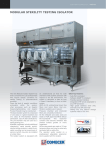
1
User’s Manual
HDAT2 v4.8
Version 1.0
29.06.2010
Lubomir Cabla / CBL
http://www.hdat2.com/
Contents
CONTENTS.........................................................................................................................................................................I
TABLES..........................................................................................................................................................................VII
PICTURES......................................................................................................................................................................VII
PREFACE...........................................................................................................................................................................8
1. HDAT2 PROGRAM.......................................................................................................................................................9
1.1 OVERVIEW.....................................................................................................................................................................9
1.2 USED INTERRUPTS, KEYS..................................................................................................................................................9
1.3 COMMON NOTES..............................................................................................................................................................9
1.5 COMMAND LINE PARAMETERS............................................................................................................................................9
/Dx Disable detection........................................................................................................................................................10
/G Set path/name for BIX file...........................................................................................................................................10
/L Create/Append HDETECT.TXT file at startup.............................................................................................................10
/M Mono display mode.....................................................................................................................................................11
/O Change output path......................................................................................................................................................11
/P Pause the detect screen.................................................................................................................................................11
/S Silent mode (no sound).................................................................................................................................................11
/T=x,y Detect timeout.......................................................................................................................................................11
/W Wake/Spin-up the drive (PUIS)....................................................................................................................................11
/X=y Special functions......................................................................................................................................................12
/Y=x Last BIOS INT13h drive number.............................................................................................................................12
/?, /H Help text
............................................................................................................................................................................................12
1.6 NOTES ABOUT USB/FIREWIRE DRIVES............................................................................................................................12
2. DETECTION OF PC RESOURCES..........................................................................................................................14
2.1 DETECTION OF BIOS....................................................................................................................................................14
2.1.1 Detection of system BIOS..................................................................................................................................14
2.1.2 Detection of PnP BIOS......................................................................................................................................14
2.1.3 Detection of BIOS32..........................................................................................................................................14
2.1.4 Detection of PCI BIOS......................................................................................................................................14
2.2 DETECTION OF CPU/RAM/BUS..................................................................................................................................14
2.3 DETECTION OF CMOS..................................................................................................................................................15
2.4 DETECTION OF ROM‘S.................................................................................................................................................15
2.5 DETECTION OF FDD.....................................................................................................................................................15
2.6 DETECTION OF PCI.......................................................................................................................................................15
2.7 DETECTION OF PCI AHCI............................................................................................................................................15
2.8 DETECTION OF ATA/ATAPI ON-BOARD.........................................................................................................................16
2.9 DETECTION OF ASPI....................................................................................................................................................16
2.10 DETECTION OF BIOS INT13H....................................................................................................................................16
2.11 DETECTION OF OPERATING SYSTEM.................................................................................................................................17
3. MENU............................................................................................................................................................................18
M1. DEVICE TESTS MENU..........................................................................................................................................19
M1.1 CHECK AND REPAIR BAD SECTORS................................................................................................................................19
M1.2 CHECK BAD SECTORS ONLY.........................................................................................................................................19
M1.3 READ AND REPAIR BAD SECTORS.................................................................................................................................19
M1.4 READ BAD SECTORS...................................................................................................................................................19
M1.5 WIPE DEVICE............................................................................................................................................................19
M1.6 SEEK DEVICE.............................................................................................................................................................19
M1.7 MOST POWERFUL TEST................................................................................................................................................19
M1.8 USER DEFINED TEST...................................................................................................................................................19
M2. FILE SYSTEM MENU............................................................................................................................................20
M2.1 READ FILE SYSTEM FROM MBR.................................................................................................................................20
M2.2 SCAN FILE SYSTEM...................................................................................................................................................20
M2.3 USER DEFINED TEST...................................................................................................................................................20
Page i
M3. DEVICE INFORMATION MENU.........................................................................................................................21
M3.1 DEVICE INFORMATION ................................................................................................................................................21
M3.2 INQUIRY DATA..........................................................................................................................................................21
M3.3 MODE SENSE DATA...................................................................................................................................................21
M3.4 VITAL PRODUCT DATA (VPD)...................................................................................................................................23
M3.5 TABLE OF CONTENTS (TOC/PMA/ATIP)..................................................................................................................24
M3.6 GET CONFIGURATION.................................................................................................................................................24
M3.7 READ DISC INFORMATION...........................................................................................................................................25
M3.8 MECHANISM STATUS..................................................................................................................................................25
M3.9 LOG SENSE...............................................................................................................................................................25
M3.9.1 Error counter log pages.................................................................................................................................26
M3.10 DUMP IDENTIFY DEVICE.................................................................................................................................27
M4. SMART MENU.........................................................................................................................................................28
The evolution of SMART...................................................................................................................................................28
The two SMART specifications: ATA/SCSI......................................................................................................................28
Some failures are predictable, and some are not.................................................................................................................29
How attributes are determined............................................................................................................................................29
Attribute values...................................................................................................................................................................30
Worst value.........................................................................................................................................................................30
Threshold Exceeded Condition (T.E.C.).............................................................................................................................30
SMART for USB hard drives..............................................................................................................................................31
M4.1.1 READ DATA..........................................................................................................................................................31
M4.1.2 READ ATTRIBUTE DATA..........................................................................................................................................31
Temperature...................................................................................................................................................................48
Write, Read and Verify Error Counter pages..................................................................................................................48
Non-medium error count................................................................................................................................................49
Self-Test Results.............................................................................................................................................................49
Last n Error Events.........................................................................................................................................................51
M4.1.4 SCSI SELF-TEST...................................................................................................................................................51
M4.1.5 SCSI SELF-TEST LOG............................................................................................................................................52
M4.1.6 SCSI ABORT BACKGROUND SELF-TEST...................................................................................................................52
M4.2 ROUTINE MENU...................................................................................................................................................53
M4.2.1 OFF-LINE..............................................................................................................................................................53
M4.2.2 SHORT SELF-TEST..................................................................................................................................................53
M4.2.3 EXTENDED SELF-TEST............................................................................................................................................54
M4.2.4 CONVEYANCE SELF-TEST........................................................................................................................................54
M4.2.5 SELECTIVE SELF-TEST............................................................................................................................................54
M4.2.6 ABORT OFF-LINE SELF-TEST ROUTINE.....................................................................................................................55
M4.3 READ LOG MENU................................................................................................................................................55
M4.3.1 LOG DIRECTORY....................................................................................................................................................56
M4.3.2 SUMMARY ERROR LOG...........................................................................................................................................56
M4.3.3 COMPREHENSIVE ERROR LOG...................................................................................................................................58
M4.3.4 EXTENDED COMPREHENSIVE ERROR LOG...................................................................................................................58
M4.3.5 SELF-TEST LOG.....................................................................................................................................................59
M4.3.6 SELECTIVE LOG......................................................................................................................................................59
M4.3.7 DUMP OF LOG PAGES............................................................................................................................................59
M4.4 COMMAND MENU...............................................................................................................................................60
M4.4.1 SAVE ATTRIBUTE VALUES.......................................................................................................................................60
M4.4.2 ATTRIBUTE AUTOSAVE............................................................................................................................................60
M4.4.3 AUTOMATIC OFF-LINE............................................................................................................................................61
M4.5 SMART COMMAND TRANSPORT (SCT) MENU..........................................................................................61
M4.5.1 ERROR RECOVERY CONTROL (ERC) MENU..............................................................................................................61
M4.5.1.1 Read Command Timer................................................................................................................................62
M4.5.1.2 Write Command Timer................................................................................................................................62
M4.5.2 FEATURE CONTROL MENU.......................................................................................................................................62
M4.5.2.1 Write Cache................................................................................................................................................62
M4.5.2.2 Write Cache reordering..............................................................................................................................63
M4.5.2.3 Time Interval for temperature logging.......................................................................................................63
Page ii
M4.5.3 DATA TABLE MENU ...............................................................................................................................................63
M4.5.3.1 HDA Temperature History..........................................................................................................................63
M4.5.4 LBA SEGMENT ACCESS/WRITE SAME MENU............................................................................................................64
M4.5.4.1 LBA Repeat Write Pattern..........................................................................................................................64
M4.5.4.2 LBA Repeat Write Sector............................................................................................................................64
M4.5.5 SCT STATUS PAGE (E0H).......................................................................................................................................64
M6. HIDDEN AREAS MENU.........................................................................................................................................65
M6.1 OVERVIEW OF HIDDEN AREAS....................................................................................................................................66
M6.2 AUTO REMOVE HIDDEN AREAS...................................................................................................................................66
M6.3 DUMP OF HPA AREA.................................................................................................................................................66
M6.4 DUMP OF DCO AREA................................................................................................................................................66
M7. DEVICE CONFIGURATION OVERLAY (DCO) MENU..................................................................................67
ATA/ATAPI Device Configuration Overlay (DCO)......................................................................................................67
SATA II Device Configuration Overlay (DCO).............................................................................................................67
M7.1 SHOW IDENTIFY.........................................................................................................................................................67
M7.2 MODIFY...................................................................................................................................................................67
Example of the restrictions on changing of bits:.................................................................................................................68
Maximum LBA sectors restrictions....................................................................................................................................68
Host Protected Area feature set restrictions........................................................................................................................68
M7.3 RESTORE..................................................................................................................................................................68
M7.4 FREEZE LOCK...........................................................................................................................................................69
M7.5 CHECK DCO STRUCTURE..........................................................................................................................................69
M7.6 DUMP DCO.............................................................................................................................................................69
M8. SECURITY MENU...................................................................................................................................................71
Security Mode feature set .......................................................................................................................................................71
Master Password Identifier feature..........................................................................................................................................72
User password lost..................................................................................................................................................................72
Attempt limit for SECURITY UNLOCK command................................................................................................................73
M8.1 SET PASSWORD.........................................................................................................................................................73
M8.2 FREEZE LOCK...........................................................................................................................................................73
M8.3 UNLOCK...................................................................................................................................................................74
M8.4 DISABLE PASSWORD..................................................................................................................................................74
M8.5 ERASE UNIT.............................................................................................................................................................74
M8.6 UNLOCK DEVICE........................................................................................................................................................76
M9. SET MAX (HPA) MENU.........................................................................................................................................77
M9.1 SET MAX ADDRESS...................................................................................................................................................77
M9.2 SET PASSWORD.........................................................................................................................................................79
M9.3 LOCK.......................................................................................................................................................................79
M9.4 UNLOCK...................................................................................................................................................................79
M9.5 FREEZE LOCK...........................................................................................................................................................80
M9.6 AUTO REMOVE HPA AREA.......................................................................................................................................80
M10. QUANTUM MENU................................................................................................................................................81
M10.1 READ DEFECT LIST.................................................................................................................................................81
M10.2 READ CONFIGURATION.............................................................................................................................................81
M10.2.1 DisCache Parameters..................................................................................................................................82
PE - Prefetch Enable [default bit=1]...................................................................................................................................82
CE - Cache Enable [default bit=1]......................................................................................................................................82
M10.2.2 Error Recovery Parameters.........................................................................................................................82
AWRE - Automatic Write Reallocation enabled [default bit=1].....................................................................................82
ARR - Automatic Read Reallocation enabled [default bit=1].........................................................................................82
RC - Read Continuous [default bit=0]............................................................................................................................82
EEC - Enable Early Correction [default bit=0]...............................................................................................................82
Silent Mode enabled.......................................................................................................................................................82
DCR - Disable Correction [default bit=0].......................................................................................................................83
Number of Retries [default byte=8]................................................................................................................................83
ECC Correction Span [default byte=32].........................................................................................................................83
M10.2.3 Device Parameters.......................................................................................................................................83
WCE - Write Cache Enable [default=1].........................................................................................................................83
RUEE - Reallocate Uncorrectable Error Enables [default=1].........................................................................................83
Page iii
M11. DUMP/SAVE MENU.............................................................................................................................................84
M11.1 SAVE DEBUG DATA.............................................................................................................................................84
M11.2 SAVE DETECT DATA................................................................................................................................................84
M.13 COMMANDS MENU.............................................................................................................................................85
M13.1 COMMAND/FEATURE SETS.........................................................................................................................................85
M13.1.1 SMART feature set.......................................................................................................................................85
M13.1.2 Security feature set.......................................................................................................................................85
M13.1.3 Removable Media feature set.......................................................................................................................85
M13.1.4 Power Management feature set...................................................................................................................86
M13.1.5 PACKET Command feature set...................................................................................................................86
M13.1.6 Write Cache.................................................................................................................................................86
M13.1.7 Read Cache (look-ahead)............................................................................................................................86
M13.1.8 Release interrupt..........................................................................................................................................86
M13.1.9 SERVICE interrupt.......................................................................................................................................86
M13.1.10 DEVICE RESET command........................................................................................................................87
M13.1.11 Host Protected Area (HPA) feature set.....................................................................................................87
M13.1.12 WRITE BUFFER command.......................................................................................................................87
M13.1.13 READ BUFFER command.........................................................................................................................87
M13.1.14 NOP command...........................................................................................................................................87
M13.1.15 DOWNLOAD MICROCODE command....................................................................................................87
M13.1.16 READ/WRITE DMA QUEUED command.................................................................................................87
M13.1.17 Compact Flash (CFA) feature set..............................................................................................................87
M13.1.18 Advanced Power Management (APM) feature set.....................................................................................87
M13.1.19 Removable Media Status feature set..........................................................................................................88
M13.1.20 Power-Up in Standby (PUIS) feature set...................................................................................................88
M13.1.21 SET FEATURES subcommand required to spinup after power-up...........................................................88
M13.1.22 Address Offset Mode Reserved Area Boot.................................................................................................88
M13.1.23 SET MAX security extension......................................................................................................................90
M13.1.24 Automatic Acoustic Management (AAM) feature set.................................................................................90
M13.1.25 48-bit Address feature set..........................................................................................................................90
M13.1.26 Device Configuration Overlay (DCO) feature set.....................................................................................91
M13.1.27 FLUSH CACHE command........................................................................................................................92
M13.1.28 FLUSH CACHE EXT command................................................................................................................92
M13.1.29 SMART error logging................................................................................................................................92
M13.1.30 SMART self-test..........................................................................................................................................92
M13.1.31 Media serial number..................................................................................................................................92
M13.1.32 Media Card Pass Through Command feature set......................................................................................92
M13.1.33 Streaming feature set.................................................................................................................................93
M13.1.34 General Purpose Logging (GPL) feature set.............................................................................................93
M13.1.35 WRITE DMA/MULTIPLE FUA EXT commands.......................................................................................93
M13.1.36 WRITE DMA QUEUED FUA EXT command...........................................................................................93
M13.1.37 World Wide Name......................................................................................................................................93
M13.1.38 URG bit for READ STREAM DMA/EXT commands.................................................................................93
M13.1.39 URG bit for WRITE STREAM DMA/EXT commands................................................................................94
M13.1.40 Time Limited Commands (TLC) feature set...............................................................................................94
M13.1.41 Read/Write Continuous mode in TLC feature............................................................................................94
M13.1.42 IDLE IMMEDIATE with UNLOAD FEATURE.........................................................................................94
M13.2 VIEW/SEARCH DEVICE.............................................................................................................................................96
View device.................................................................................................................................................................96
Search device..............................................................................................................................................................96
M13.3 ATA COMMANDS...................................................................................................................................................97
M13.4 SATA COMMANDS.................................................................................................................................................97
M13.4.1 Reset SATA log 11h......................................................................................................................................97
M13.5 SCSI COMMANDS...................................................................................................................................................97
M13.5.1 SCSI Reset....................................................................................................................................................97
M13.5.2 Read Defect PList........................................................................................................................................97
M13.5.3 Read Defect GList........................................................................................................................................97
4. PARAMETERS............................................................................................................................................................97
4.1 DEVICE ACCESS.............................................................................................................................................................98
4.2 TEST PROCEDURE..........................................................................................................................................................98
Page iv
4.2.1 Verify.................................................................................................................................................................99
4.2.2 blockVerify........................................................................................................................................................99
4.2.3 VerifyWriteVerify..............................................................................................................................................99
4.2.4 blockVerifyWriteVerify......................................................................................................................................99
4.2.5 Read.................................................................................................................................................................100
4.2.6 ReadReadCompare..........................................................................................................................................100
4.2.7 ReadWrite........................................................................................................................................................100
4.2.8 ReadWriteRead................................................................................................................................................101
4.2.9 ReadWriteReadCompare.................................................................................................................................101
4.2.10 Wipe...............................................................................................................................................................102
4.2.11 WipeReadWipe..............................................................................................................................................102
4.2.12 ReadECC.......................................................................................................................................................102
4.2.13 WriteECC......................................................................................................................................................102
4.2.14 Seek................................................................................................................................................................103
4.3 DIRECTION OF TESTING.................................................................................................................................................103
4.4 GROUP OF TESTED SECTORS...........................................................................................................................................103
4.5 FIRST SECTOR.............................................................................................................................................................103
4.6 LAST SECTOR..............................................................................................................................................................103
4.7 DISABLE SMART FOR TEST........................................................................................................................................103
4.8 NUMBER OF TESTS.......................................................................................................................................................104
4.9 COUNT OF RETRY ON ERROR..........................................................................................................................................104
4.10 DEVICE RESET ON ERROR............................................................................................................................................104
4.11 SHOW C/H/S...........................................................................................................................................................104
4.12 SOUND (CTRL+S)..................................................................................................................................................104
4.13 PAUSE ON DETECT SCREEN..........................................................................................................................................104
4.14 RUNNING MODE........................................................................................................................................................105
4.15 READ/SCAN MODE....................................................................................................................................................105
4.16 LBA/CHS MODE.....................................................................................................................................................105
4.17 BOUNDARY MODE......................................................................................................................................................105
4.18 CHECK BOOT SIGNATURE............................................................................................................................................105
4.19 PREVENT REMOVAL....................................................................................................................................................105
4.20 EJECT MEDIUM..........................................................................................................................................................105
4.21 DIR: ROOT ONLY..................................................................................................................................................106
4.22 SHOW ECC.............................................................................................................................................................106
4.23 FILL WRITE BUFFER....................................................................................................................................................106
4.24 INSERT DATE/TIME STAMP...........................................................................................................................................106
4.25 SET K-PREFIX VALUE.................................................................................................................................................106
4.26 ADDRESSING MODE....................................................................................................................................................106
4.27 SEARCH OBJECT........................................................................................................................................................107
4.28 STRING: CASE SENSITIVE.............................................................................................................................................107
4.29 STRING: TYPE...........................................................................................................................................................107
4.30 STRING: POSITION IN SECTOR.......................................................................................................................................107
4.31 MODE SENSE DATA VALUES.......................................................................................................................................107
4.32 LOG SENSE DATA VALUES.........................................................................................................................................108
S1. SCSI DEFECTS........................................................................................................................................................109
Medium defects.........................................................................................................................................................109
Primary defect list (PLIST)...................................................................................................................................................109
Logical unit certification list (CLIST)...................................................................................................................................109
Data defect list (DLIST)........................................................................................................................................................109
Grown defect list (GLIST)....................................................................................................................................................109
Write failures............................................................................................................................................................110
X. MESSAGES................................................................................................................................................................111
X.1 DEVICE STATUS MESSAGES.........................................................................................................................................111
X.1.1 !SET MAX:......................................................................................................................................................111
X.1.2 !SMART:.........................................................................................................................................................111
X.1.3 !SECURITY:....................................................................................................................................................112
X.1.4 !DCO:.............................................................................................................................................................113
X.1.5 !ATA MODE:..................................................................................................................................................113
X.1.6 !EDD:..............................................................................................................................................................113
X.1.7 !OFFSET:.......................................................................................................................................................113
X.1.8 !POWER:........................................................................................................................................................113
Page v
X.2 ERROR MESSAGES OF INT13H/EXT.INT13H...............................................................................................................114
X.3 ERROR MESSAGES OF ASPI........................................................................................................................................115
ASPI Host Error Messages...............................................................................................................................................115
ASPI Target Error Messages.............................................................................................................................................116
ASPI Command/SRB Error Messages..............................................................................................................................116
X.4 ERROR MESSAGES OF PNP..........................................................................................................................................116
X.5 ERROR MESSAGES OF ESCD......................................................................................................................................117
Z. REFERENCES................................................................................................................................................................119
Page vi
Tables
TABLE 1: USED FILE NAMES ......................................................................................................................................9
TABLE 2: PRE-DEFINED ADDRESS..........................................................................................................................16
TABLE 3: MODE SENSE PAGE CODES....................................................................................................................22
TABLE 4: VITAL PRODUCT DATA (VPD) CODES.................................................................................................23
TABLE 5: SEAGATE VPD PAGES...............................................................................................................................24
TABLE 6: LIST OF PROFILES.....................................................................................................................................24
TABLE 7: LOG PAGE CODES......................................................................................................................................25
TABLE 8: QUANTUM LOG SENSE PAGES..............................................................................................................26
TABLE 9: VENDOR LOG SENSE PAGES..................................................................................................................26
TABLE 10: PARAMETER CODES FOR ERROR COUNTER LOG PAGES.........................................................26
TABLE 11: SMART ATTRIBUTES..............................................................................................................................33
TABLE 12: SMART ATTRIBUTES FOR SSD ONLY................................................................................................43
TABLE 13: SELF-TEST RESULTS VALUE................................................................................................................50
TABLE 14: SMART DIRECTORY LOG......................................................................................................................56
TABLE 15: IDENTIFIER AND SECURITY LEVEL BIT INTERACTION............................................................73
Pictures
PICTURE 1: DEVICE MENU........................................................................................................................................18
PICTURE 2: CHECK DCO STRUCTURE...................................................................................................................69
PICTURE 3: DUMP DCO...............................................................................................................................................70
Page vii
Preface
This manual is for HDAT2 program. Program is designed for advanced users, you have to know
what you are doing.
I am sorry for my English.
Motto: Do you know how hard it is to write a manual?
Page 8
1. HDAT2 Program
1.1 Overview
Program HDAT2 run in protected mode and is compiled with 32-bits compiler Free Pascal.
Program HDAT2 can be used in two levels:
•
•
Device Tests – tests for devices connected to PC
File System - tests for file systems (FAT only, so far)
Program is running only under any "real" DOS operating system (not in DOS under Windows).
In DOS under Windows you can use a demo program HDAT2DEM.EXE only.
1.2 Used interrupts, keys
HDAT2 program install own interrupts:
•
for INT09h (keyboard)
Keys ESC, PAUSE, which normally interrupts program, make only pause of action. Pressing
keys CTRL+BREAK should always break program and return to operating system (only if
system is not running in a loop of interrupt). You should see a text "!! HARD BREAK !!" on the
screen.
Any time you can enable or disable sound with key CTRL+S regardless to settings of
parameter /s.
1.3 Common notes
Program detects the device modes up to Ultra DMA 6 for ATA/133 from standard ATA/ATAPI. If
some ATA mode is internally disabled (using a company SW) than device seems do not support
this mode. For correct settings, you must use again this firm SW from device manufacturer.
Program on exit is starting an alternate reset of controller and device (INT13h/AH=0Dh) for
stopping some of unacceptable noises of hard drive.
Table 1: Used file names
File Name
HDATCOPY.TXT
HDETECT.TXT
XXXXXXXX.BIX
HDAT_FST.BIX
HDAT2SCR.ERR
Description
Saved listings from program.
Saved listing of detected PC resources and devices.
Binary debug informations of device.
Saved status of the file system items.
Saved screen with error message.
XXXXXXXX = last eight characters of serial number or device name or "_GENERIC"
1.5 Command line parameters
The program accepts optional command line parameters.
Format of parameters:
Page 9
hdat2 [<switch>parameter1 <switch>parameter2 ...]
Each parameter must be preceded with a switch, program accept either a forward slash (/) or
a hyphen (-). Parameters are delimited by one or more space characters.
Items listed between brackets ([]) are optional.
Every parameter is checked for duplicity, availability and correct of setting.
In case of parameter error will be displayed order of parameter, an error message, and
parameter value:
<number_of_parameter>. <error_message>: <parameter_value>
Error messages:
Duplicate parameter
- duplicate parameter is found (given twice or multiple times)
Unknown parameter
- wrong parameter (not supported by this program)
Incorrect parameter
- switch '/' or '-' is missing; value of parameter is out of range, etc.
Parameters
/Dx
Disable detection
Default: all enabled
•
•
•
•
•
•
•
•
•
•
•
x=1 CPU/RAM/BUS
x=2 BIOS
x=3 CMOS
x=4 ROM
x=5 FDD
x=6 PCI
x=7 PCI AHCI
x=8 ATA/ATAPI
x=9 ASPI
x=10 BIOS_INT13h
x=11 OS (operating system)
You can repeat the parameters, e.g. HDAT2 /d=1,7 …
/G
Set path/name for BIX file
Default: current directory (usable for FAT only)
Syntax: /G=<drive>:\[<dir>\[<name>]]
This option is valid for demo program HDAT2DEM.EXE only.
With this option you can set and use your own BIX file instead of HDAT2DEM.BIX.
/L
Create/Append HDETECT.TXT file at startup
Page 10
Default: current directory (usable for FAT only)
It is for debug purpose only. If HDAT2 program cannot continue with error message you can
try start program with this switch. HDAT2 program will produce detect screens with useful
informations about PC and connected devices. When some error message appears and
program is halted, you can send me this LOG file for finding where is a problem.
Output device is identical with device where program is loaded from, e.g. program was loaded
from diskette A:, output log shall be written to diskette A:.
/M
Mono display mode
Default: disabled
Useable for monochrome monitor only.
/O
Change output path
Default: current directory (usable for FAT only)
Syntax: /O=<drive>:\[<dir>\]
With this option you set your own device and directory for output files.
/P
Pause the detect screen
Default: disabled
If parameter enabled and detect output screen is full, sounds a beep and is waiting for user
request to press any key. Pressing any key will be program continuing to run until screen is full
again. Except the key ESC – pressing this key shall disable setting of this parameter and
detection will continue without pause.
/S
Silent mode (no sound)
Default: disabled
Disable all beeps [NoSound]. Any time you can press CTRL+S to enable or disable this
parameter.
/T=x,y
Detect timeout
Default: x=5, y=1
Syntax: /T=x,y
x=number of seconds
y=cycle count
/W Wake/Spin-up the drive (PUIS)
Default: disabled
Page 11
Power-up in standby (PUIS) or Power Management 2 mode (PM2, Western Digital specific)
is a hard disk configuration which prevents the drive from automatic spinup when power is
applied. The spinup occurs later by an ATA command.
PM2 can usually be enabled by jumpering on the drive but can also be configured by other
means (configuration sector) using manufacturer specific tools.
PUIS requires corresponding BIOS support. If PUIS is enabled on the drive but not supported
by the BIOS, the drive will not be detected by the system or detected as zero in size. PUIS is
typically only supported on RAID controllers.
With this parameter program will try to spinup the drive and disable PUIS feature.
/X=y
Special functions
Default: settings depends on value Y
y=1 - disable DC_NIEN for ATA (e.g. use it for HighPoint)
Default: DC_NIEN is enabled.
Disable interrupt for ATA (so called DC_NIEN); main using is for add-on ATA HighPoint
controllers.
y=2 – PCI: read all registers
Default: During detection of PCI devices will read first 64 registers (00h-3Fh) only instead of
all 255 registers (00h-FFh).
PCI on some PCs is not correct implemented and by reading of all registers could be system
stop/hang. All PCI registers will be read with this parameter.
y=3 – PCI: use all storage subclasses
Default: without parameter '/x4' are used PCI subclasses 01h, 04h, 05h, 06h, 80h only.
For PCI class Storage 01h detection will be valid all subclasses (00h-FFh).
y=4 – PCI: use IO ports instead of BIOS
Default: PCI BIOS
Use IO ports instead of PCI BIOS to access PCI bus.
/Y=x
Last BIOS INT13h drive number
Default: x=239=EFh (values 0-255=00h-FFh)
You can set the last detected BIOS INT13h number.
If is used parameter /x1, on exit program will be execute a reset for all connected ATA and
ATAPI devices to prevent a time loop when device is waiting for end of interrupt.
/?, /H
Help text
1.6 Notes about USB/FireWire drives
A lot of the non-ATA interfaces (adapters) such as USB and FireWire usually only support a
limited subset of ATA or SCSI commands (the device then can converts SCSI commands into
ATA commands). And it is vendor specific for each controller chip.
So such ATA commands for read SMART data, set security (include password), set HPA etc. are
possible only for some USB controllers not for all of them.
Page 12
Note: USB adapters block most of the low level access.
Question: I was wondering if its ever going to be possible to get the SMART info off a USB
storage device?
Answer: You could at least get some kind of condition report by removing your hard disk from
its USB case, connecting it to an ATA or SATA cable in a desktop, then running the utility.
Though this ritual does not allow continuous monitoring of the USB drive, it may give a clue as
to its current status.
The same answer is for setting or removing the HPA area or security password.
Page 13
2. Detection of PC resources
At start of program or with so-called re-detect from main menu are detected some PCs
resources.
2.1 Detection of BIOS
Program detects some BIOS functions via Desktop Management Interface (DMI) interface.
2.1.1 Detection of system BIOS
BIOS (Basic Input/Output System)
- AMI, Award, Phoenix, Compaq, IBM, Quadtel, Acer, Dell, SystemSoft, Toshiba
- Detection of type BIOS, version, date, revision, model, sub-model (not for all BIOS)
- Some BIOS features
2.1.2 Detection of PnP BIOS
PnP (Plug and Play)
- Used standard:
Compaq/Phoenix/Intel: Plug and Play BIOS Specification v1.0A 05.05.1994
- Versions, CS/DS entry points
2.1.3 Detection of BIOS32
BIOS32 (BIOS32 Service Directory)
The new service will provide information about those services in the BIOS that designed for
callers running in a 32-bit code segment. (The BIOS32 Service Directory will itself be a 32-bit
BIOS service.) The expected clients of this service are 32-bit operating systems and 32-bit
device drivers. The expected providers of this service are BIOS vendors that implement one or
more 32-bit BIOS services. The BIOS32 Service Directory proposal came into being during the
attempts to establish a 32-bit code interface for the Peripheral Component Interconnect (PCI)
standard.
The BIOS32 Service Directory proposal came into being during the attempts to establish a 32bit code interface for the Peripheral Component Interconnect (PCI) standard.
- Used standard:
Standard BIOS 32-bit Service Directory Proposal, Revision 0.4, 18.06.1993
Phoenix Technologies Ltd., PC Division, Desktop Product Line
2.1.4 Detection of PCI BIOS
PCI (Peripheral Component Interconnect)
- Used standard: PCI BIOS v2.0c+.
2.2 Detection of CPU/RAM/BUS
Page 14
- Processor (type, CPUID)
- Memory (RAM)
- Bus (EISA, MCA, ISA, PCI)
2.3 Detection of CMOS
CMOS (Complementary Metal Oxide Semiconductor)
-
Test of CMOS presence (real-time bit)
Show 'CMOS size'
Show 'POST diagnostics status'
Show 'Shutdown/Reset status'
2.4 Detection of ROM‘s
ROM (Read Only Memory)
First scan memory from C000h:0000h to F000h:0000h with offset 200h (512 bytes). After
scanning it shows PnP/PCI informations about found ROM‘s.
2.5 Detection of FDD
FDD (Floppy Disk Drive)
- Detect device type of ATA FDD on on-board ATA controllers
- Detect count of FDD according to CMOS memory and BIOS detection
- If FDD is not present in CMOS settings, but is connected, it is neither possible detect nor test
FDD!
- Does it test of two FDD drives
- Test of presence FDD
- Test FDD with max. BIOS parameters – we got a type of drive
2.6 Detection of PCI
PCI (Peripheral Component Interconnect)
By PCI detection will be detect host devices of class 1 (Storage) and all subclasses defined for
class 1 (SCSI, IDE, Floppy, IPI, RAID, ADMA, SATA, SAS) only. For every found PCI host
device will show some important information like:
- bus number, device and function (Bus, Device, Function)
- identification number of manufacturer (Vendor ID) and host device (Device ID),
name of manufacturer (if is known)
- I/O port addresses
- system interrupt IRQ and PCI interrupt from INT#A to INT#D
- Bus Master support
On these PCI host devices will be detected PCI devices. When it was no device found, it
appears 'No PCI devices found'.
2.7 Detection of PCI AHCI
Advanced Host Controller Interface (AHCI)
Page 15
The Advanced Host Controller Interface (AHCI) is an application programming interface defined
by Intel which defines the operation of Serial ATA host bus adapters. The specification
describes a system memory structure for computer hardware vendors to exchange data
between host system memory and attached storage devices.
AHCI gives software developers and hardware designers a standard method for detecting,
configuring, and programming SATA/AHCI adapters.
By PCI AHCI detection will be detect AHCI controller.
2.8 Detection of ATA/ATAPI on-board
It is perform detection of devices on primary (1F0h) and secondary (170h) channel, tertiary
(1E8h) and quaternary (1F0h) channel. On every channel are detected always two devices:
drive 0 and 1 (master and slave).
Table 2: Pre-defined address
Controller
Primary
Secondary
Tertiary
Quaternary
PC3000
Addresses
1F0h (1F0-1F7h/3F0h)
170h (170-177h/370h)
1E8h (1E8-1EFh/3E0h)
168h (168-16Fh/360h)
100h
INT
14/0Eh
15/0Fh
11 (alt. 12,9)
11 (alt. 12,9)
The devices will appears in form:
[c/d 0xxxh/0yyyh/irq] description
c
: number of controller (at detection)
d
: 0=master, 1=slave
0xxxh
: base address of ATA registers (hexadecimal)
0yyyh
: alternate address of ATA registers (hexadecimal)
irq
: number of interrupt
description : device name
Text 'disabled or not present' in field ‘description’ means that on given controller and
channel is not present any device or if is disabled in BIOS.
2.9 Detection of ASPI
ASPI (Advanced SCSI Programming Interface)
With loaded ASPI driver for given SCSI controller we got on detection more information than
without driver. It will be detected all host adapters and all devices via ID and LUN from 0 to
255. With ASPI driver we can detect devices connected via SCSI controller, parallel port etc. devices like SCSI hard disk, CD, ZIP.
2.10 Detection of BIOS INT13h
This detection will detect devices connected in system via BIOS interrupt INT13h. Detection
will be successfully only if device supports extended interrupt INT13h (Extended INT13h).
With this detection, we find out e.g. devices like SCSI hard drive even in case not loaded ASPI
drivers but with constraint of obtained informations about device.
Page 16
E.g. if is enabled detection 'BIOS_INT13h' only, it will not detect ATAPI devices like CD-ROM,
because these devices does not use interrupt INT13h even extended INT13h.
2.11 Detection of operating system
Finally we will detect and display type of the running operating system.
If is detected operating system like 'Windows DOS', 'OS/2 DOS', 'WinNT/2K DOS', 'Windows',
'Desqview' or 'Linux DOS emulation', appears message 'This program cannot be run in
multitask environment' and program exit.
Page 17
3. Menu
The contents of the menu that appears depend on the type of device, type of device detection
and supported features.
Examples:
1. Menu items specified only for devices as CD/DVD does not appear for devices as hard disk,
respectively. The same is valid for PATA/SATA devices vs. SCSI or USB devices.
2. If hard disk does not support Host Protected Area feature set the menu item for Set Max
Address will not be displayed.
3. If hard disk does not support SET MAX security extension feature the menu items for SET
MAX security (Set Password, Lock, Unlock, Freeze Lock) will not be displayed.
4. If hard disk does not support Host Protected Area feature set and SET MAX security
extension feature the whole menu for SET MAX will not be displayed.
Supported features or commands can you find in Commands Menu - Command/Feature sets or
in Device Information Menu – Device Information.
Picture 1: Device Menu
Page 18
M1. Device Tests Menu
Coming in the next version.
M1.1 Check and Repair bad sectors
Serious bad sector: no ECC/DRQ possible
Logical defects: ECC/DRQ is possible
Physical defects: surface damages (scratches)
M1.2 Check bad sectors only
M1.3 Read and Repair bad sectors
M1.4 Read bad sectors
M1.5 Wipe device
M1.6 Seek device
From ATA/ATAPI-7 is command SEEK obsolete.
M1.7 Most powerful test
Read defined block of sectors into memory 1, write this block of sectors onto device, read the
same defined block of sectors into memory 2 and compare memory 1 and 2.
M1.8 User defined test
Page 19
M2. File System Menu
M2.1 Read File System from MBR
M2.2 Scan File System
This test is not fully implemented so you can use it "as it is". I want to implement many things,
sometimes.
M2.3 User defined test
Page 20
M3. Device Information Menu
There are miscellaneous information about selected device.
M3.1 Device Information
This option it will show all available information obtained from interface ATA/ATAPI (from
IDENTIFY DEVICE or IDENTIFY DEVICE PACKET command), BIOS tables, from interrupt
INT13h and Extended INT13h, from ASPI drivers.
M3.2 Inquiry Data
This option is valid only for ATAPI, SCSI, or USB devices. For SCSI and USB devices only in
case with loaded ASPI driver.
The INQUIRY command requests that information regarding identification of the Logical Unit be
send to the Initiator. Options allow the Initiator to request additional information about the
Logical Unit like product identification, peripheral device type, product revision level etc.
M3.3 Mode Sense Data
This option is valid only for ATAPI, SCSI, or USB devices. For SCSI and USB devices only in
case with loaded ASPI driver.
The MODE SENSE command provides a means for a device server to report parameters to an
application client. The page control field specifies the type of mode parameter values, which
will returned in the mode pages: current, changeable, default and saved values.
Current values
The current values returned are:
a) The current values of the mode parameters established by the last successful MODE SELECT
command.
b) The saved values of the mode parameters if a MODE SELECT command has not successfully
completed since the mode parameters were restored to their saved values or
c) The default values of the mode parameters if a MODE SELECT command has not
successfully completed since the mode parameters were restored to their default values.
Changeable values
In the mask, the bits in the fields of the mode parameters that are changeable all shall be set
to one and the bits in the fields of the mode parameters that are non-changeable (i.e., defined
by the logical unit) all shall be set to zero.
Default values
The default values of the mode parameters; unsupported parameters shall be set to zero.
Default values should be accessible even if the logical unit is not ready.
Saved values
Page 21
The method of saving parameters is vendor specific. The parameters are preserved in such a
manner that they are retained when the device is powered down.
Table 3: Mode sense page codes
Page
00h
Subpage
00h
01h
02h
03h
00h
00h
00h
04h
00h
05h
00h
06h
00h
07h
08h
09h
0Ah
0Bh
0Ch
0Dh
00h
00h
00h
00h
01h
F1h
F2h
00h
00h
00h
0Eh
00h
0Fh
10h
00h
00h
11h
14h
15h
16h
18h
19h
1Ah
1Bh
1Ch
00h
00h
00h
00h
00h
00h
00h
00h
00h
1Dh
01h
00h
1Eh
1Fh
20h-3Eh
22h
2Ah
2Ch
Page 22
00h
00h
00h
00h
Description
Vendor specific (does not require page format)
Unit Attention Page
Configuration page (tape)
Drive Operation
Read-Write Error Recovery
Disconnect/Reconnect
Format Device (SBC)
Parallel Printer Interface (SSC)
MRW CD-RW (MMC)
Rigid Disk Drive Geometry (SBC)
Serial Printer Interface (SSC)
Flexible Disk (SBC)
Printer Options (SSC)
Write Parameters (MMC)
Optical Memory (SBC)
RBC Device Parameters (RBC)
Verify Error Recovery
Caching
Peripheral Device (obsolete)
Control Mode
Control Extension
Parallel ATA Control
Serial ATA Control
Medium Types Supported
Notch and Partition
Obsolete
CD Device Parameters (MMC)
CD Audio Control parameters (MMC)
ADC Device Configuration (ADC)
Data Compression
XOR Control (SBC)
Device Configuration (SSC)
Medium Partition (1)
Enclosure Services Management
Extended
Extended Device-Type Specific
Protocol Specific LUN
Protocol Specific Port
Power Condition
LUN Mapping
Informational Exceptions Control
Fault/Failure Reporting (MMC)
Background Control
Time-Out and Protect (MMC)
Element Address Assignments (SMC)
Transport Geometry Parameters
Device Capabilities
Device-type specific (vendor specific in common usage)
LCD Mode
CD/DVD Capabilities and Mechanical Status
MRW CD-RW
M3.4 Vital Product Data (VPD)
This option is valid only for ATAPI, SCSI, or USB devices (For SCSI and USB devices only in
case with loaded ASPI driver).
These vital product data (VPD) pages are returned by an INQUIRY command with the EVPD
bit set to one and contain vendor specific product information about a logical unit and target
device. The vital product data may include vendor identification, product identification, unit
serial numbers, device operating definitions, manufacturing data (e.g., plant and date of
manufacture), field replaceable unit information, and other vendor specific or device specific
information. The standard defines the structure of the vital product data, but not the contents.
Table 4: Vital product data (VPD) codes
Page
00h
01h-7Fh
80h
81h
82h
83h
84h
85h
86h
87h
88h
89h
8Ah
8Bh
90h
91h
B0h
B1h
B2h
B3h
C0h-FFh
C0h
C1h
C2h
C3h
D0h
D1h
D2h
Description
Supported VPD Pages
ASCII Information
Unit Serial Number
Implemented Operating Definition
ASCII Implemented Operating Definition
Device Identification
Software Interface Identification
Management Network Addresses
Extended Inquiry Data
Mode Page Policy
SCSI Ports
ATA Information
Power Condition
Device Constituents
Protocol Specific Logical Unit Information
Protocol Specific Port Information
Block Limits
Block Device Characteristics
Thin Provisioning
Referrals
Vendor specific
Firmware Revision
Operation Mode (Fujitsu)
Date Code
Unique Identification (Quantum)
Manufacturing Number (Maxtor)
Jumper Settings
Negotiated Rate Information (Quantum)
Device Behavior
Queue Depth
(Hitachi)
(Hitachi)
Page 80h provides the product serial number and product circuit board number for the drive.
Page 81h defines the current operating definition, the default operating definition, and which
operating definitions are implemented by the drive. These operating definition values are
specified in the Change Definition command.
The Device Identification page 83h provides the means to retrieve zero or more identification
descriptors applying to the logical unit. Logical units may have more than one identification
Page 23
descriptor (e.g., if several types or associations of identifier are supported). Device identifiers,
if any, shall be assigned to the peripheral device (e.g., a disk drive) and not to the currently
mounted media, in the case of removable media devices. Operating systems are expected to
use the device identifiers during system configuration activities to determine whether alternate
paths exist for the same peripheral device.
Table 5: Seagate VPD Pages
Page
C0h
C1h
C2h
C3h
D1-D4h
Description
Firmware Numbers
Date Code
Jumper Settings
Device Behavior
Vendor specific
M3.5 Table of Contents (TOC/PMA/ATIP)
This option is valid only for ATAPI or SCSI device type of CD-ROM (For SCSI devices only in
case with loaded ASPI driver).
M3.6 Get Configuration
This option is valid only for ATAPI device type of CD-ROM.
The GET CONFIGURATION command provides information about the Logical Unit capabilities both current and potential. It returns supported features (set of commands, pages, and
behavior that may be implemented) and profile list (collections of features and provide a
methods to quickly determine the Logical Unit’s type).
Table 6: List of profiles
Profile
0000h
0001h
0002h
0003h
0004h
0005h
0008h
0009h
000Ah
0010h
0011h
0012h
0013h
0014h
0015h
0016h
001Ah
001Bh
002Ah
002Bh
0040h
0041h
0042h
Page 24
Description
No Current Profile
Non-Removeable Disk
Removeable Disk
Magneto-Optical Eraseable
Optical Write Once
AS-MO
CD-ROM
CD-R
CD-RW
DVD-ROM
DVD-R Sequential recording
DVD-RAM
DVD-RW Restricted Overwrite
DVD-RW Sequential Recording
DVD-R Dual Layer Sequential Recording
DVD-R Dual Layer Jump Recording
DVD+RW
DVD+R
DVD+RW Dual Layer
DVD+R Dual Layer
BD-ROM
BD-R Sequential Recording (SRM)
BD-R Random Recording (RRM)
0043h
0050h
0051h
0052h
FFFFh
BD-RE
HD DVD-ROM
HD DVD-R
HD DVD-RAM
Drives not conforming to a standard profile
M3.7 Read Disc Information
This option is valid only for ATAPI device type of CD-ROM.
The READ DISC INFORMATION command allows the Initiator to request information about the
currently mounted disc like formats supported by device, erasable medium, state of last
session, recorded status of the disc (empty, incomplete, finalized).
M3.8 Mechanism Status
This option is valid only for ATAPI device type of CD-ROM.
The Mechanism Status command requests that the Logical Unit respond with the current status
of the device, including any Changer Mechanism that adheres to the standard. This command
is intended to provide information to the Initiator about the current operational state of the
Logical Unit. The Logical Unit takes operational direction from both the Initiator and the user.
Movement of media in/out of the Logical Unit as well as Play operations may be due to
external controls or Initiator commands. This command provides a method that allows the
Initiator to know what has transpired with the changer mechanism.
M3.9 Log Sense
The LOG SENSE command provides a means for the application client to retrieve statistical or
other operational information maintained by the SCSI target device about the SCSI target
device or its logical units.
The drive collects operational information and stores these statistics as log data. Log data are
grouped by category into log pages. The LOG SENSE command allows an initiator to retrieve
the stored log data. The LOG SENSE command is a complementary command to the LOG
SELECT command.
Each log page contains one or more pieces of information. Each piece of information is referred
to as a parameter. There are two types of parameters: values and lists. In general, error and
performance counters are reported as values.
Log Sense data pages require special interpretation and also are subject to change.
Table 7: Log Page codes
Page
00h
01h
02h
03h
04h
05h
06h
07h
08h
Subpage
00h
00h
00h
00h
00h
00h
00h
00h
00h
Description
Supported Log Pages
Buffer Over-Run/Under-Run
Write Error Counter
Read Error Counter
Read Reverse Error Counter
Verify Error Counter
Non-Medium Error Counter
Last n-Error Events
Format Status
Page 25
09h
0Ah
0Bh
0Dh
0Eh
0Fh
10h
15h
17h
18h
19h
1Ah
2Fh
30h-3Eh
3Fh
00h-FFh
00h-FFh
00h
00h
00h
00h
00h
00h
00h
00h
Reserved to the MS59 Std. (contact AIIM C21 comm.)
Reserved to the MS59 Std. (contact AIIM C21 comm.)
Last n-Deferred Error or Asynchronous Events
Temperature
Start-Stop Cycle Counter
Application Client
Self-Test Results
Background Medium Scan Results
Non-volatile Cache
Protocol Specific Port
General Statistics and Performance
Power Condition Transitions
Informational Exceptions/SMART
Vendor specific (does not require page format)
Reserved
00h
00h-FFh
00h-FFh
Table 8: Quantum Log Sense Pages
Page
31h
36h
37h
38h
39h
3Ah
3Bh
3Dh
3Eh
3Fh
Subpage
Description
Last 500 Errors
Early Warning System (EWS)
Seek Performance Summary
Servo Events Counter
Bad Block Replacement Summary
Disk Error Recovery Counters
DER Description
ECC Counters and Sumary
SCSI Bus Events
ECC On The Fly
Table 9: Vendor Log Sense Pages
Page
30h
Subpage
37h
38h
3Eh
Description
SMART Attitude (Seagate)
Performance Counters (Hitachi)
Cache statistics (Seagate)
SMART Data (Fujitsu)
Factory (Seagate)
M3.9.1 Error counter log pages
SCSI SPC standard defines the error counter log pages:
02h
03h
04h
05h
– Write Error Counter
– Read Error Counter
– Read Reverse Error Counter
- Verify Error Counter
A log page may return one or more log parameters that record events
defined by the parameter codes.
Table 10: Parameter codes for error counter log pages
Parameter code
0000h
0001h
Page 26
Description
Errors corrected without substantial delay
Errors corrected with possible delays
0002h
0003h
0004h
0005h
0006h
0007h-7FFFh
8000h-FFFFh
Total (e.g., rewrites or rereads)
Total errors corrected
Total times correction algorithm processed
Total bytes processed
Total uncorrected errors
Reserved
Vendor specific
M3.10 Dump IDENTIFY DEVICE
This option will show 512 bytes as result from ATA or ATAPI command IDENTIFY DEVICE.
Page 27
M4. SMART Menu
The SMART is "Self Monitoring and Reporting Technology". It is a standard interface
allowing a hard disk drive to check its status, report it to host system, and provide some
estimation for a failure date.
It is actually set of subroutines in device firmware, which are doing diagnostics functions. The
SMART in BIOS only checks the status of the drive at boot time and can enable or disable
SMART, but cannot run operation of diagnostics tests.
The evolution of SMART
Reliability prediction technology emerged from a widely recognized need to protect missioncritical information stored on disc drives. As system storage capacity requirements increased
and multiple disc array systems started to appear, industry leaders identified the importance of
creating an early warning system that would allow enough lead time to back up data, should a
failure become imminent. In order to understand how SMART evolved, it is necessary to look
at SMART's roots, which are based in technology developed by IBM and Compaq.
IBM's reliability prediction technology is called Predictive Failure Analysis (PFA). PFA
measures several attributes, including head flying height, to predict failures. The disc drive,
upon sensing degradation of an attribute, such as flying height, sends a notice to the host that
a failure may occur. Upon receiving notice, users can take steps to protect their data.
Some time later, Compaq announced a breakthrough in diagnostic design called IntelliSafe.
This technology, which was developed in conjunction with Seagate, Quantum, and Conner,
monitors a range of attributes and sends attribute and threshold information to host software.
The disc drive then decides if an alert is warranted, and sends that message to the system,
along with the attribute and threshold information. The attribute and threshold level
implementation of IntelliSafe varies with each disc drive vendor, but the interface, and the way
in which status is sent to the host, are consistent across all vendors.
Compaq placed IntelliSafe in the public domain by presenting their specification for the
ATA/IDE environment, SFF-8035, to the Small Form Factor Committee on May 12, 1995.
Seagate quickly recognized that reliability prediction technology offered tremendous benefits to
customers, and researched the possibility of making a version available to other system OEMs,
integrators, and independent software vendors. Conner, IBM, Quantum and Western Digital
joined Seagate in the development of this new version, appropriately named SMART, which
combines conceptual elements of Compaq's IntelliSafe and IBM's PFA.
Features of SMART technology include a series of attributes, or diagnostics, chosen specifically
for each individual drive model. Attribute individualism is important because drive
architectures vary from model to model. Attributes and thresholds that detect failure for one
model may not be functional for another model. Comparing different models of car’s helps
illustrate this point. Some cars are equipped with four-wheel drive, but others, like a Cadillac,
are not. In other words, the architecture of the drive will determine which attributes to
measure, and which thresholds to employ. Although not all failures will be predicted, we can
expect an evolution of SMART, as technology and experience sharpen our ability to predict
reliability. Subsequent changes to attributes and thresholds will also occur as field experience
allows improvements to the prediction technology.
The two SMART specifications: ATA/SCSI
SMART emerged for the ATA/IDE environment when SFF-8035 was placed in the public
domain. SCSI drives incorporate a different industry standard specification, as defined in the
Page 28
ANSI-SCSI Informational Exception Control (IEC) document X3T10/94-190. Seagate's
SMART System program includes both industry standards, thereby making SMART technology
available for both products with either ATA, or SCSI interfaces.
The SMART system technology of attributes and thresholds is similar in ATA/IDE and SCSI
environments, but the reporting of information differs.
In an ATA/ environment, software on the host interprets the alarm signal from the drive
generated by the "report status" command of SMART The host polls the drive on a regular
basis to check the status of this command, and if it signals imminent failure, sends an alarm to
the end user or system administrator. This allows downtime to be scheduled by the system
administrator to allow for backup of data and replacement of the drive. This structure also
allows for future enhancements, which might allow reporting of information other than drive
conditions, such as thermal alarms, CD-ROM, tape, or other I/O reporting. The host system
can evaluate the attributes and alarms reported, in addition to the "report status" command
from the disc.
Generally speaking, SCSI drives with reliability prediction capability only communicate a
reliability condition as either good or failing. In a SCSI environment, the failure decision occurs
at the disc drive, and the host notifies the user for action. The SCSI specification provides for a
sense bit to be flagged if the disc drive determines that a reliability issue exists. The system
then alerts the end user/system manager.
Some failures are predictable, and some are not
A disc drive must be able to monitor many elements in order to have a comprehensive
reliability management capability. One of the most crucial elements understands failures.
Failures can be seen from two standpoints: predictable, and unpredictable.
Unpredictable failures occur quickly, like electronic and mechanical problems, such as a
power surge that can cause chip or circuit failure. Improvements in quality, design, process,
and manufacturing can reduce the incidence of non-predictable failures. For example, the
development of steel-belted radial tires reduced the occurrences of blowouts common among
older flat wall "rag" tire designs.
Predictable failures are characterized by degradation of an attribute over time, before the
disc drive fails. This creates a situation where attributes can be monitored, making it possible
for predictive failure analysis. Many mechanical failures are typically considered predictable,
such as the degradation of head flying height, which would indicate a potential head crash.
Certain electronic failures may show degradation before failing, but more commonly,
mechanical problems are gradual and predictable. For instance, oil level is a function, or
"attribute" of most cars that can be monitored. When a car's diagnostic system senses that the
oil is low, an oil light comes on. The driver can stop the car and save the engine. In the same
manner, SMART allows notice to start the backup procedure and save the user's data.
Mechanical failures, which are mainly predictable failures, account for 60 percent of drive
failure. This number is significant because it demonstrates a great opportunity for reliability
prediction technology. With the emerging technology of SMART, an increasing number of
predictable failures will be predicted, and data loss will be avoided.
By monitoring hard disk health, you will be able to predict most of disk failures and avoid
data losing.
How attributes are determined
SMART technology is like a jigsaw puzzle; it takes many pieces, put together in the right way,
to make a pattern. As previously discussed, understanding failures are one piece of the puzzle.
Another piece of the puzzle is the way in which attributes are determined. Attributes are
Page 29
reliability prediction parameters, customized by the manufacturer for different types of drives.
To determine attributes, manufacturer design engineers review returned drives, consider the
design points, and create attributes to signal the types of failures that they are seeing.
Information gained from field experience can be used to predict reliability exposures and, over
time, attributes can be incorporated into the new reliability architecture.
Though attributes are drive-specific, a variety of typical characteristics can be identified:
•
•
•
•
•
•
•
•
head flying height
data throughput performance
spin-up time
re-allocated sector count
seek error rate
seek time performance
spin try recount
drive calibration retry count
The attributes listed above illustrate typical kinds of reliability indicators. Ultimately, the disc
drive design determines which attributes the manufacturer will choose. Attributes are therefore
considered proprietary, since they depend on drive design.
SMART attribute is a specific property of disk being monitored. Every SMART attribute has a
set of properties: attribute value, its threshold, worst attribute value and raw value. Specific
threshold is assigned to each attribute. Once the attribute value drops below this threshold,
SMART considers disk to be faulty.
Attribute values
Attribute values are used to represent the relative reliability of individual performance or
calibration attributes. The current attribute value is the normalized raw attribute data. The
value varies between 1 and 100. The closer the value gets to one, the higher the
possibility of a failure. The device compares the attribute values with thresholds. When the
attribute values are larger than the thresholds, the device is operating normally. Attributes are
being used to retrieve current state of a drive and to show their meaning in much more
readable form for end-user.
Raw attribute data (6 bytes)
Usually it shows exact amount of time, attempts or errors. For example: the raw value of
attribute Temperature is a drive temperature in Celsius degrees, the raw value of Power on
hours count attribute is a amount of hours when drive was in power-on state.
Attribute threshold (1 byte)
This is the lowest limit of a varying attribute value. SMART compares the attribute values with
the thresholds to identify a failure. Each attribute value has a corresponding attribute
threshold limit. The numerical values of the attribute thresholds are determined by the
device manufacturer through design and reliability testing and analysis. Attribute thresholds
are set at the device manufacturer’s factory and cannot be changed in the field. The valid
range for attribute thresholds is from 1 through 253 decimal.
Worst value
The worst attribute value among the attribute values collected to date. This value indicates the
state nearest to a failure so far.
Threshold Exceeded Condition (T.E.C.)
Page 30
T.E.C. stands for "Threshold Exceeded Condition" and basically means a failure. If one or
more attribute values are less than or equal to their corresponding attribute thresholds, then
the device reliability status indicates an impending degrading or fault condition. Some
attributes are considered life-critical and others are merely "informative". T.E.C. with an
"informative" attribute does not necessarily mean drive failure.
SMART for USB hard drives
The majority of drives connected via USB and Firewire are not supported. The protocol bridge
between the USB and ATA protocols doesn't seem to support SMART data.
Some SMART-enabled motherboards and related software may not communicate with certain
SMART-capable drives, depending on the type of interface. Few external drives connected via
USB and Firewire correctly send SMART data over those interfaces. With so many ways to
connect a hard drive (e.g. SCSI, Fibre Channel, ATA, SATA, SAS, SSA) it's difficult to predict
whether SMART reports will function correctly.
M4.1.1 Read Data
This command returns the Device SMART data structure to the host. This data structure
contains status bytes, collection and error logging capability, and estimated polling time for
SMART routines.
M4.1.2 Read Attribute Data
SMART attribute is a specific property (parameter) of disk being monitored. The attribute is
referred to either by its number or by its descriptive name. Attribute value is a positive integral
number, usually in range from 1 to 100 (or sometimes 1 to 200, max. 255). Maximum values
are good, minimum values indicate that some component of the disk is about to fail. Specific
threshold is assigned to each attribute. Once the value drops below this threshold, SMART
considers disk to be faulty – it is happen T.E.C.
Maximum number of attributes is 30. Numbers of attributes depends on manufacturer.
Remember that attributes are no longer part of the ATA standard, but most manufacturers still
support them. Although SFF-8035i does not define the meaning or interpretation of attributes,
many have a de facto standard interpretation. Each attribute has a six-byte raw value (RAW
VALUE) and a one-byte normalized value (VALUE).
The format of the raw data is vendor-specific and not specified by any standard. To track disk
reliability, the disk's firmware converts the raw value to a normalized value ranging from 1 to
254. If this normalized value is less than or equal to the threshold (THRESH), the attribute is
said to have failed.
Program only reports the different attribute types, values, and thresholds as read from the
device. It does not carry out the conversion between "Raw" and "Normalized"
values: this is done by the disk's firmware.
The conversion from Raw value to a quantity with physical units is not specified by the SMART
standard. In most cases, the values printed are sensible. For example the temperature
attribute generally has its raw value equal to the temperature in Celsius. The raw SMART
attributes (temperature, power-on lifetime, and so on) are stored in vendor-specific structures.
For example the Hitachi disk reports its power-on hours in minutes, not hours. Some IBM disks
track three temperatures rather than one, in their raw values.
Some firmware (Western Digital) initializes SMART some attributes (10, 11, and 199) after
either several spin-ups or power-on hours. Until that time, they have the uninitialized value
253 and the worst value is larger than current attribute value.
Page 31
Each attribute also has a "WORST" value. This is the smallest (closest to failure) value that
the disk has recorded at any time during its lifetime when SMART was enabled. Note however
that some vendors firmware may actually increase the "Worst" value for some "rate-type"
attributes.
The TYPE of the attribute indicates if attribute failure means the device has reached the end of
its design life (Old age) or it is an impending disk failure (Pre-failure). For example, disk spinup time (ID 3) is a prefailure attribute. If this (or any other prefail attribute) fails, disk failure
is (imminent) predicted in less than 24 hours.
Pre-failure attributes are ones which, if less than or equal to their threshold values, indicate
pending disk failure. Old age, or usage attributes, are ones which indicate end-of-product life
from old-age or normal aging and wearout, if the attribute value is less than or equal to the
threshold. The fact that an attribute is of type 'Pre-fail' does not mean that your disk is about
to fail! It only has this meaning if the attribute's current Normalized value is less than or equal
to the threshold value.
If the worst recorded value is less than or equal to the threshold value, then appears a
message "^ Failed in the past" in red color.
It could occur so called false error - SMART firmware report a warning, but the device is
good. Common reason of false errors is that device has problem with power supply or in short
time was exposed to crucial changes in temperature.
Each attribute can have a certain collection of flags (types to determine his importance):
•
Pre-Failure (PF, 01h) – marked with a sign "!"
It is labeled sometimes like Life Critical (CR) or Pre-Failure warranty (PW). If
attribute has this flag then a field threshold contains a minimal allowed value under
which is not guaranteed work ability of device and increases a possibility his
inactivation.
Indicates a pre-failure condition (caused by exceeded threshold) where imminent loss
of data is being predicated.
•
Online Collection (OC, 02h)
Determine that value of this attribute will acquired during performing of on-line SMART
tests or both of tests (on-line/off-line). On the contrary, value of attribute will acquired
only during off-line tests.
It indicates that the value of this attribute is calculated during online test.
•
Performance Related (PR, 04h)
Determine that value of this attribute direct depend on device performance in some
indicators (seek/throughput/etc. performance). Usually is re-establishing after
execution of SMART tests.
It indicates degradation of performance caused by usage or age of a drive.
•
Error Rate (ER, 08h)
Value of this attribute reflect relative error rate of given attribute - raw read/write,
seek, etc.
Indicates that attribute measure frequency of errors.
•
Events Count (EC, 10h)
Sometimes is labeled like Error Count. Attribute is an events counter.
•
Self-Preserving (SP, 20h)
Value of attribute is restoring and saving automatically - usually at every start of device
and at execution of SMART tests.
Indicates that attribute is automatically preservable and restored each time when
Page 32
performing SMART tests.
Each attribute has its own value, meaning, and importance. Unfortunately, each manufacturer
can make extensions to SMART attributes and most of them prefer to keep their own
extensions in secret. Some disk manufacturers use their own ID’s for attributes.
The names/meanings of attributes and the interpretation of their raw values is not specified by
any standard. Different manufacturers sometimes use the same attribute ID for different
purposes.
Unfortunately, as you can see, this table is not complete and, most likely, on your HDD shows
some attributes with the name "Unknown attribute". It means that I do not have any
information about the name and meaning of this attribute.
Table 11: SMART attributes
ID
0
1
2
3
4
5
6
7
8
9
ID hex.
00h
01h
02h
03h
04h
05h
06h
07h
08h
09h
10
11
12
13
99
100
101
183
184
185
186
187
188
189
190
0Ah
0Bh
0Ch
0Dh
63h
64h
65h
B7h
B8h
B9h
BAh
BBh
BCh
BDh
BEh
191
BFh
192
C0h
193
194
195
C1h
C2h
C3h
196
C4h
197
198
199
200
C5h
C6h
C7h
C8h
Description
Invalid attribute identifier (not in use)
Raw Read Error Rate
Throughput Performance
Spin Up Time
Start/Stop Count
Reallocated Sector Count
Read Channel Margin
Seek Error Rate
Seek Time Performance
Power-On Hours Count
Power-On Time Count
Spin-Up Retry Count
Drive Calibration Retry Count
Drive Power Cycle Count
Soft Read Error Rate
Average FHC (Fly-Height Controller) (Maxtor)
Minimum FHC (Fly-Height Controller) (Maxtor)
Maximum FHC (Fly-Height Controller) (Maxtor)
SATA Downshift Error Count
End-to-end Error Count
Head Stability
Induced Op-Vibration Detection
Uncorrectable Error Count
Command Timeout Error Count
High Fly Writes
Airflow Temperature
Temperature Difference from 100 (Seagate)
G-Sense/Shock Error Rate
Shock Sense (WDC)
Power-Off Retract Count
Emergency Retract Cycle Count (Fujitsu,WDC)
Load/Unload Cycle Count
HDA Temperature
Hardware ECC Recovered
ECC On The Fly Count (Fujitsu,WDC)
Reallocation Event Count
Re-allocated Sector Event (WDC)
Current Pending Sectors Count
Off-line Uncorrectable Sector Count
Ultra DMA CRC Error Rate
Write Error Rate/ Write Error Count
Page 33
201
C9h
202
CAh
203
CBh
204
CCh
205
CDh
206
207
208
209
210
211
CEh
CFh
D0h
D1h
D2h
D3h
212
213
214
215
216
217
218
220
221
D4h
D5h
D6h
D7h
D8h
D9h
DAh
DCh
DDh
222
223
224
225
226
227
228
230
231
240
DEh
DFh
E0h
E1h
E2h
E3h
E4h
E6h
E7h
F0h
241
242
250
254
F1h
F2h
FAh
FEh
Multi-Zone Error Rate (WDC)
Soft Read Error Rate
Off Track Errors Count (Maxtor)
Detected TA Count (Fujitsu)
Data Address Mark (DAM) Errors
TA Increase Count (Fujitsu)
ECC Errors
Run Out Cancel (Fujitsu,WDC)
Soft ECC Correction
Shock Count Write Opern (Fujitsu)
Thermal Asperity Rate
Shock Rate Write Opern (Fujitsu)
Flying Height
Spin High Current
Spin Buzz
Offline Seek Performance
Vibration During Write
Vibration During Read
Spin Running Current (Hitachi)
Shock During Write
Gr seek err/RRO-C ERP Count
Ground Load Errors Count
Ground SpinUp Errors
Unexpectant Errors Count
Unlock/Mis Read Count
FlashROM ECC Corr. Count
Disk Shift
G-Sense Error Rate
Shock Sense Error Rate (Hitachi)
Loaded Hours
Load/Unload Retry Count
Load Friction
Load/Unload Cycle Count
Load-In Time
Torque Amplification Count
Power-Off Retract Count
GMR Head Amplitude
Drive Temperature
Head Flying Hours (Hitachi)
Transfer Error Rate (Fujitsu)
Total LBA Writes (IBM)
Total LBA Reads (IBM)
Read Error Retry Rate
G Sensor Error Rate Count
Free Fall Protection (Seagate)
Description of some attributes:
1. Raw Read Error Rate
Raw read error is very hard to interpret.
This attribute value depends of read errors, disk surface condition and indicates the rate of
hardware read errors that occurred when reading data from a disk surface. Lower values
indicate that there is a problem with either disk surface or read/write heads. Frequency of
errors appearance while reading RAW data from disk.
Page 34
Count of non-corrected read errors. More errors (i.e. lower attribute value) mean worse
condition of disk surface.
Frequency of errors while reading raw data from a disk.
"Read Error Rate" indicates the rate of hardware read errors that occurred when reading data
from a disk surface. A non-zero value indicates a problem with either the disk surface or
read/write heads. Note that Seagate drives often report a raw value that is very high even on
new drives, and does not thereby indicate a failure.
2. Throughput Performance
Overall (general) throughput performance (average efficiency) of hard disk drive. If the value
of this attribute is deceasing, there is a high probability of troubles with your disk.
3. Spin Up Time
Average time of spindle spin up (from zero RPM (Revolutions per Minute) to fully operational).
"Spin up time" describes amount of time it took to spin the platters up to their rated rotation
speed (usually 5400 or 7200 RPM) - average time of spindle spin up time. Values above 80
should be considered good. Values between 70 and 80 are still acceptable. There is a known
issue with Quantum (Maxtor) hard drives - out-of-the-box new drives drop "Spin up time" to
70 within first two weeks of use, causing program to predict failure within a month. This is
usually a false alarm. After some initial "burn-in" period, "Spin up time" becomes constant and
the drive functions normally.
The raw value of this attribute indicates average time to spin up the drive spindle. Raw value
is a time of milliseconds or seconds.
4. Start/Stop Count
Count of spindle start/stop cycles. Raw value probably shows total number of on/off HDD.
Raw value of this attribute (Raw shows on/off Spindle Motors) indicates total number of drive
start/stop cycles (including both power on/off switching and suspend/wakeup switching).
This raw value of this attribute is a count of hard disk spindle start/stop cycles.
5. Reallocated Sectors Count
Indicates amount of spare sector pool (spare area) available. Spare sectors are used to replace
(reallocating, remapping) sectors that became bad for some reason (read or write errors).
Value of 100 means that no sectors were remapped, 1 means that spare sectors are exhausted
due to multiple remaps.
Count of reallocated sectors. When the hard drive finds a read/write/verification error, it marks
this sector as "reallocated" and transfers data to a special reserved area (spare area). This
process is also known as remapping and "reallocated" sectors are called remaps. This is why,
on a modern hard disks, you cannot see "bad blocks" while testing the surface - all bad blocks
are hidden in reallocated sectors. However, the more sectors that are reallocated, the more a
sudden decrease (up to 10% and more) can be noticed in the disk read/write speed.
The more sectors reallocated (i.e. lower attribute value), the worse the condition of disk
surface. The raw value of this attribute shows exact amount of reallocated sectors.
Reallocation Event Count is not zero - this means drive found some weak sectors and marked
them pending. But later it was able to successfully recover these sectors (by reading or writing
them). Reallocation Event Count records both successful and unsuccessful tries.
Page 35
6. Read Channel Margin
Margin of a channel while reading data. The function of this attribute is not specified.
Reserve of channel while reading
7. Seek Error Rate
Seek errors are usually a power problem or a vibration problem. They may also indicate a
problem with the disk.
Count of seeks errors. When your HDD reads data, it positions heads in the needed place. If
there is a failure in the mechanical positioning system, a seek error arises. More seek errors
(i.e. lower attribute value) - indicates worse condition of a disk surface and disk mechanical
subsystem. Frequency of errors appearance while positioning.
Average rate of seek errors. This attribute indicates a state of head positioning mechanism.
Lower values shows that there is a problem with head positioning.
Rate of seek errors of the magnetic heads. If there is a failure in the mechanical positioning
system, servo damage or a thermal widening of the hard disk, seek errors arise. More seek
errors indicates a worsening condition of a disk surface and the disk mechanical subsystem.
"Seek Error Rate" - Rate of seek errors of the magnetic heads. If there is a partial failure in the
mechanical positioning system, then seek errors will arise. Such a failure may be due to
numerous factors, such as damage to a servo, or thermal widening of the hard disk. More seek
errors indicates a worsening condition of a disk's surface or the mechanical subsystem, or
both. Note that Seagate drives often report a raw value that is very high, even on new drives,
and this does not normally indicate a failure.
8. Seek Time Performance
Disk seeks system performance. The average efficiency of operations while positioning.
Average performance of seek operations of the magnetic heads. If this attribute is decreasing,
it is a sign of problems in the hard disk drive mechanical subsystem.
9. Power On Hours Count
Count of hours in power-on state. The raw value of this attribute shows total count of hours
(or minutes, or seconds, depending on manufacturer) in power-on state. A decrease of this
attribute value to the critical level (threshold) indicates a decrease of the MTBF (Mean Time
Between Failures). However, in reality, even if the MTBF value falls to zero, it does not mean
that the MTBF resource is completely exhausted and the drive will not function normally.
Raw value of this attribute indicates how long the drive was working (powered on).
Sense of attribute is identical with attribute "Device/Drive Power Cycle Count", which
shows count of start/stop cycles of hard drive. Decreasing of value to threshold means
exhausted lifetime of drive (MTBF - Mean Time Between Failures).
New models of Maxtor use Attribute 9 to store the power-on disk lifetime in minutes rather
than hours. Some models of Fujitsu disks use Attribute 9 to store the power-on disk lifetime in
seconds.
10. Spin Up Retry Count
Page 36
Indicates number of times disk was unable to spin platters up on first attempt (lower values
mean more retries). Count of retry of drive spindle spins start attempts. The raw value
indicates amount of retries.
Number of attempts to start a spindle of disk. If the HDD cannot start its spindle on the first
try (to make HDD work), it makes another try - and so on while the spindle will not rotate
normally. This attribute stores a count of start retries.
Count of retry of spin start attempts. This attribute stores a total count of the spin start
attempts to reach the fully operational speed (under the condition that the first attempt was
unsuccessful). A decrease of this attribute value is a sign of problems in the hard disk
mechanical subsystem.
11. Calibration Retry Count (Recalibration Retries Count)
Indicates number of times recalibration was requested. Low value (multiple recalibrations)
usually indicates some head-positioning problem. Number of attempts to calibrate a drive.
Calibration is the act of repositioning the drive read/write head to cylinder 0. This value
represents the number of times a calibration has failed on the first attempt.
This attribute indicates the number of times recalibration was requested (under the condition
that the first attempt was unsuccessful). A decrease of this attribute value is a sign of
problems in the hard disk mechanical subsystem.
12. Device Power Cycle Count
The Power Cycle Count attribute indicates the total number of times power has cycled
on the drive. It probably means "start - stop" (power on - power off) of hard drive. Attribute
importance is identical to "Power-On Hours".
Number of complete start/stop cycles of hard disk. The raw value indicates amount of power
cycles. This attribute indicates the count of full hard disk power on/off cycles.
13. Soft Read Error Rate
ECC repairable read errors. This is a software error, not a hardware error. This is the rate of
"program" read errors occurring when reading data from a disk surface.
99. Average FHC
100. Minimum FHC
101. Maximum FHC
For FHC (Fly-Height Controller) see "System and method for determining head-disk contact
in a magnetic recording disk drive by magnetoresistive signal amplitude” (United States Patent
7292401).
183. SATA Downshift Error Count
Used by Samsung and Western Digital.
184. End-to-end error count
This attribute is a part of HP's SMART IV technology and it means that after transferring
through the cache RAM data buffer the parity data between the host and the hard drive did not
match.
Page 37
Tracks the number of end to end internal card data path errors that were detected.
Starting in late 2007, new HP business desktops and Workstations will begin incorporating
SMART IV technology in hard drives. While the current versions of SMART do a good job
monitoring the data on the hard drive media, the ever increasing emphasis on reliability and
quality led Hewlett-Packard and hard drive manufacturers to better ensure that the data flow
from host interface to media and media to host interface is not compromised. This is done by
adding a parity code to every 512 byte block in the data path of the hard drive's Cache RAM.
This parity checking, which is called SMART IV by HP, provides more complete error detection
coverage of the entire data path between the host and the hard drive. In the hard drive
industry, SMART IV is also known as End-to-End Error Detection.
- If an error is detected by the drive and the data cannot be retrieved or sent without failure, a
protocol is in place to notify the host operating system of the error. The host operating system
can then decide to resend the command or notify the user that a data error may have
occurred.
- If errors are detected, a SMART attribute called End-to-End Error Detection Count is updated.
If the SMART threshold is crossed, an imminent failure error message is reported to the user
either through Client Management Software that has been installed in the operating system or
by the HP BIOS on the next reboot.
188. Command Timeout
It means number of commands were aborted because of timeout - drive wasn't able to read or
write properly in a reasonable time period.
191. G-Sense Error Rate
Frequency of mistakes appearance as a result of impact loads.
192. Power-Off Retract Count
The Power-Off Retract Count attribute returns the number of times the drive has been
powered-off. This value is one less than the Power-Cycle Count attribute value.
Number of power-off or emergency retract cycles.
Number of the fixed‚ turning off drive cycles.
Count of fixed pictures with power-off retracts of power supply of disk.
Unknown function on IBM drives. Is possibly a count of the number of times the drive head
was moved off the disk in a power down situation?
Fujitsu: "Emergency Retract Cycle Count”.
193. Load/Unload Cycle Count
Count of load/unload (LUL) cycles for heads moving into special park zone or working position
(Landing Zone).
194. HDA Temperature
The Temperature attribute indicates the current drive (HDA: a hard disk assembly)
temperature in degrees Celsius (°C) for drives equipped with thermal sensor. Exact
temperature can be obtained from the Meaning column.
195. Hardware ECC Recovered
Frequency of the on the fly errors.
Page 38
Fujitsu: "ECC On the Fly Count”.
196. Reallocation Event Count
It is count of sectors reallocation. Value raw indicates total count of attempts, successful and
not successful.
Count of remap operations (transferring data from a bad sector to a special reserved disk area
- spare area). The raw value of this attribute shows the total number of attempts to transfer
data from reallocated sectors to a spare area. Unsuccessful attempts are counted as well as
successful.
Reallocation Event Count means drive found some weak sectors and marked them pending.
But later it was able to successfully recover these sectors (by reading or writing them).
Reallocation Event Count records both successful and unsuccessful tries.
A bad sector marked by the disk (and invisible to the operating system) can be counted as
"reallocation event" or "reallocated sector count". If these numbers start growing, something is
seriously wrong.
197. Current Pending Sector Count
Amount of pending sectors. If the sector issues and error during read or write the drive marks
it as pending for a certain time before replacing this error sector with a spare one.
Current count of unstable sectors (waiting for remapping). The raw value of this attribute
indicates the total number of sectors waiting for remapping. Later, when some of these sectors
are read successfully, the value is decreased. If errors still occur when reading some sector,
the hard drive will try to restore the data, transfer it to the reserved disk area (spare area) and
mark this sector as remapped. If this attribute value remains at zero, it indicates that the
quality of the corresponding surface area is low.
Those are sectors that couldn't be properly read and that the hard disk logic is waiting for a
write operation to try to remap to a spare sector (if available). A simple disk surface scan
won't be enough to force the remap operation. You need a read/write surface scan to remap
the sector. The best option should be a tool that knows about what should be read from that
sector so that it has some option to apply the best fix to the missing data.
The Current Pending Sector Count of one reflects a sector that has been marked as bad by the
operating system. I suspect that the drive's controller is aware that it is bad, but it cannot
relocate it until such time as the system writes to it, thereby signalling that the data in that
sector is no longer of any consequence.
It represents a sector that the drive has given up on, but not yet been able to replace, because
it was not written to it. The system does not factor into this.
198. Off-line Scan Uncorrectable Sector Count
Amount of error sectors detected during the last off-line scan. Count of uncorrectable
read/write sector errors. Growth of value row means worse condition of disk surface and/or
mechanical subsystem.
The Uncorrectable Errors Count attribute returns the number of uncorrectable ECC errors
(Error Correction Codes) that occurred. This counter increments if more than four bits in the
affected sector
are uncorrectable. The raw value of this attribute indicates the total number of uncorrectable
errors when reading/writing a sector. A rise in the value of this attribute indicates that there
Page 39
are evident defects of the disk surface and/or there are problems in the hard disk drive
mechanical subsystem.
Those are sectors that an offline scanning found as unreadable. Offline scanning is a process
that can be automatically started by the hard disk logic when a long enough idle period is
detected or that can be forced by some tool. Those unreadable sectors are identified and the
hard disk logic is waiting for a write command that will overwrite them to try to remap them to
spare sectors (if available).
199. Ultra DMA CRC Error Rate
The UDMA CRC Error Count attribute indicates the number of sectors that encountered
a CRC error (Cyclic Redundancy Check) while in UDMA mode. Just one more method of error
control in data transfer operations, but for high-speed transfer modes.
UDMA controller performs an error checking on data it receives from HDD, ensuring that data
was not damaged while transmitted over the cable. Each time the error is detected, controller
requests a retransmission, thus slowing down the overall transfer speed. Lower values of
"Ultra ATA/DMA CRC Error Rate" correspond to higher number of errors, usually indicating a
cabling problem. Just change your cable.
Value raw contain count of errors occurred in Ultra DMA transfer data mode in control sum
(ICRC - Interface CRC). In practice these CRC errors arise at over clocking PCI bus (more
then 33.6 MHz), strong twisted cable and from drivers, which does not observe demand for
receive/send data in Ultra DMA mode.
200. Write Error Rate/Count
Indicates a rate at which write retries are requested. Lower values indicate that there is a
problem with either disk surface or read/write heads.
The raw value indicates amount of write errors. Frequency of errors appearance while
recording data into disk.
Count of non-corrected write errors. Write data errors rate. This attribute indicates the total
number of errors found when writing a sector. The higher raw (i.e. more errors, lower
attribute value), the worse condition of disk surface condition and/or mechanical subsystem is.
Western Digital: Multi Zone Error Rate.
201. Soft Read Error Rate (TA Counter Detected)
Frequency of the off track errors.
202. Data Address Mark Errors (TA Increase Count)
Frequency of the Data Address Mark errors.
Number of Data Address Mark (DAM) errors (or) vendor-specific.
203. Run Out Cancel
Frequency of the ECC errors.
Maxtor: "ECC Errors”
204. Soft ECC Correction
Quantity of errors corrected by software ECC.
Page 40
205. Thermal Asperity Rate (TAR)
Frequency of the thermal asperity errors.
206. Flying Height
The height of the disk heads above the disk surface.
207. Spin High Current
Quantity of used high current to spin up drive.
208. Spin Buzz
Quantity of used buzz routines to spin up drive.
209. Offline Seek Performance
Drives seek performance during offline operations.
220. Disk Shift
Shift of disk volume relate to axis of spindle. Actual value of attribute is in field raw. The shift
could happen as a result of heavy hit on device, by device fall or otherwise.
Shift of disk is possible as a result of strong shock loading in the store, as a result of its falling
or for other reasons (sometimes temperature).
Shift of disks towards spindle. The raw value of this attribute indicates how much the disk has
shifted. Unit measure is unknown. For more info see on Seagate website Seagate G-Force
Protection.
NOTE: Shift of disks is possible as a result of a strong shock or a fall, or for other reasons.
221. G-Sense Error Rate
Errors rate in consequence to shock overload. This attribute saves the data from sensor
sensitive to shock. (Unknown function on IBM drives)
This attribute is an indication of shock-sensitive sensor – total quantity of errors appearance as
a result of impact loads (for example dropping drive).
Rate of errors occurring as a result of impact loads. This attribute stores an indication of a
shock-sensitive sensor, that is, the total quantity of errors occurring as a result of internal
impact loads (dropping drive, wrong installation, etc.). For more info on Seagate website
Seagate G-Force Protection.
222. Loaded Hours
The load to head drive raised by total work time of mechanics. It takes only account of time,
when the heads are in working position.
Loading on magnetic heads actuator caused by the general operating time. Only time when the
actuator was in the operating position is counted.
223. Load/Unload Retry Count
Page 41
The loads to head drive raised by many times retry of operation read, write, and seek of heads
and the like. It takes only account of time, when the heads are in working position. (Unknown
function on IBM drives)
Loading on magnetic heads actuator caused by numerous recurrences of operations like
reading, recording, positioning of heads, etc. Only the time when heads were in the operating
position is counted.
224. Load Friction
Loading on magnetic heads actuator caused by friction in mechanical parts of the store. Only
the time when heads were in the operating/working position is counted.
225. Load/Unload Cycle Count
Total of cycles of loading on drive.
226. Load-In Time
The total loads to head drive. It takes only account of time, when the heads are in working
position (not in park zone). General time of loading for drive.
Total time of loading on the magnetic heads actuator. This attribute indicates total time in
which the drive was under load (on the assumption that the magnetic heads were in operating
mode and out of the parking area).
227. Torque Amplification Count
Amount of power of drive torque (moment amplifier). Count of efforts of the rotating moment
of a drive.
228. Power-Off Retract Count
This attribute shows a count of the number of times the drive was powered down.
Number of power-off retract events.
230. GMR Head Amplitude
Amplitude of heads vibration/trembling (GMR head) in working/running state.
231. Drive Temperature
Hard disk drive temperature. The raw value of this attribute shows built-in heat sensor
registrations (in degrees centigrade).
Studies have shown that lowering disk temperatures by as little as 5°C significantly reduces
failure rates, though this is less of an issue for the latest generation of fluid-drive bearing
drives. One of the simplest and least expensive steps you can take to ensure disk reliability is
to add a cooling fan that blows cooling air directly onto or past the system's disks.
In this case, the raw value stores three temperatures: the disk's temperature in Celsius (29),
plus its lifetime minimum (23) and maximum (33) values. The format of the raw data is
vendor-specific and not specified by any standard.
240. Head Flying Hours (Hitachi)
Time while head is positioning.
Page 42
Modern drive heads float over the surface of the disk and do all of their work without ever
physically touching the platters they are magnetizing. The amount of space between the heads
and the platters is called the floating height or flying height. It is also sometimes called the
head gap, and some hard disk manufacturers refer to the heads as riding on an "air
bearing".
If a drive is used at too high an altitude, the air will become too thin to support the heads at
their proper operating height and failure will result; special industrial drives that truly are
sealed from the outside are made for these special applications.
Some modern drives include sensors that monitor the flying height of the heads and signal a
warning if the parameter falls out of the acceptable range.
240. Transfer Error Rate (Fujitsu)
If the device receives the reset during transferring the data, the transfer error is counted up.
250. Read Error Retry Rate
Indicates a rate at which read retries is requested. Lower values indicate that there is a
problem with either disk surface or read/write heads. Frequency of errors appearance while
reading data from a disk.
254. Free Fall Protection
Number of "Free Fall Events" detected.
Table 12: SMART attributes for SSD only
ID ID hex.
0
00h
100
64h
103
67h
130
82h
170
AAh
171
ABh
172
ACh
173
ADh
174
AEh
175
AFh
176
B0h
177
B1h
178
B2h
179
B3h
180
B4h
181
B5h
182
B6h
183
B7h
184
B8h
192
C0h
195
C3h
196
C4h
197
C5h
198
199
200
C6h
C7h
C8h
Description
Invalid attribute identifier (not in use)
Erase/Program Cycles Count
Translation Table Rebuild
Minimum Spares
Reserved Block Count
Program Fail Count
Erase Fail Count
Wear Leveling Count
Unexpected Power Loss
Program Fail Count (chip)
Erase Fail Count (chip)
Wear Leveling Count
Used Reserved Block Count (chip)
Used Reserved Block Count (total)
Unused Reserved Block Count (total)
Program Fail Count (total)
Erase Fail Count (total)
Runtime Bad Block (total)
Initial Bad Block Count
Unsafe Shutdown Count
Program Failure Block Count
Erase Failure Block Count
Read Failure Block Count
(Uncorrectable Bit Errors)
Total Count of Read Sectors
Total Count of Write Sectors
Total Count of Read Commands
Used Reserved Block Count
Page 43
201
C9h
202
Cah
203
CBh
204
205
206
207
208
209
225
229
232
CCh
CDh
Ceh
CFh
D0h
D1h
E1h
E5h
E8h
233
E9h
234
EAh
235
EBh
251
252
253
254
FBh
FCh
FDh
FEh
Total Count of Write Commands
Program Fail Count
Total Count of Error Bits from Flash
Erase Fail Count
Total Count of Read Sectors with Correctable Bit Errors
Wear Leveling Count
Bad Block Full Flag
Maximum PE Count Specification
Minimum Erase Count
Maximum Erase Count
Average Erase Count
Remaining Drive Life in % by Erase Count
Host Writes
Halt System ID, Flash ID
Firmware Version Information
Endurance Remaining
Available Reserved Space
ECC Fail Record
Power-On Time
Media Wearout Indicator
Average Erase Count, Max Erase Count
Uncorrectable ECC Count
Good Block Count, System Block Count
Good Block Rate
Minimum Reserve Flash Block Count
New-Added Bad Flash Block Count
Abnormal Shutdown Count
Total Erase Flash Block Count
Description of some SSD SMART attributes:
Apacer: 229, 232, 234-235
Adtron: 130, 232-235
Delkin: 175-183,
Indilinx: 199, 205-209
Intel: 192, 225, 232-233
STEC: 100, 103, 170-174
Transcend: 184, 195-208, 229, 232-235
Many SMART attributes that are used with hard disk drives (i.e. all of those that are related to
the mechanical nature of a HDD, such as such as Seek Error Rate, Spin-up time, etc) are not
relevant for solid state drives.
Drive degradation and potential causes of failures within solid state drives are related to the
wear out of the flash blocks inside the drive.
100. Erase/Program Cycles
Count of erase program cycles for entire card.
103. Translation Table Rebuild
Power backup fault or internal error resulting in loss of system unit tables.
130. Minimum Spares
Minimum Spares - the number of spare blocks remaining as a value from 1% to 100%.
Page 44
Specifies the number of spare blocks remaining as a percentage of the spare blocks in the
worst wear-leveling zone.
170. Reserved Block Count
Number of reserved spares for bad block handling.
171. Program Fail Count
Count of flash program failures.
172. Erase Fail Count
Count of flash erase command failures.
173,177,203. Wear Leveling Count
Worst case erase count.
The NAND flash devices are limited by a certain number of write cycles. When using a FATbased file system, frequent FAT table updates are required. If some area on the flash wears
out faster than others, it would significantly reduce the lifetime of the whole SSD, even if the
erase counts of others are far from the write cycle limit. Thus, if the write cycles can be
distributed evenly across the media, the lifetime of the media can
be prolonged significantly. This scheme is called wear leveling.
174. Unexpected Power Loss
Attribute counts number of unexpected power loss events.
205. Maximum PE Count Specification
PE means program/erase cycle.
225. Host Writes
This attribute reports the total number of sectors written by the host system. The raw value is
increased by 1 for every 65,536 sectors written by the host.
229. Halt System ID, Flash ID
Attribute represent halt system and flash ID.
232. Firmware Version Information
Transcend
Attribute stores YYMMDD, number of channels and banks.
232. Endurance Remaining
Adtron
The Endurance Remaining attribute reports the number of physical erase cycles completed on
the drive as a percentage of the maximum physical erase cycles the drive supports. Because
the maximum physical erase cycles is a theoretical number (100,000), a low value in this
attribute does not necessarily mean the drive will fail. In other words, the drive may exceed
the maximum number of erase cycles, causing the drive to report 0%, without impacting drive
performance.
Page 45
232. Available Reserved Space
Intel
This attribute reports the number of reserve blocks remaining. The attribute value begins at
100 (64h), which indicates that the reserved space is 100 percent available. The threshold
value for this attribute is 10 percent availability, which indicates that the drive is close to its
end of life. Use the Normalized value for this attribute.
233. ECC Fail Record
Transcend
This attribute reports ECC fail number, row address, channel and bank number of last ECC fail.
233. Power-On Time
Adtron
The Power-On Time attribute indicates the total number of seconds the drive has been
operational. This timer starts when the drive is manufactured in production and continues
whenever the drive is powered on.
233. Media Wear Out Indicator
Intel
This attribute reports the number of cycles the NAND media has experienced. The normalized
value declines linearly from 100 to 1 as the average erase cycle count increases from 0 to the
maximum rated cycles. Once the normalized value reaches 1, the number will not decrease,
although it is likely that significant additional wear can be put on the device. Use the
Normalized value for this attribute.
234. Average Erase Count, Max Erase Count
Transcend
The average and maximum number of erase count of all the blocks.
234. Uncorrectable ECC Count
Adtron
The Uncorrectable ECC Count attribute stores the total number of ECC errors the drive
encountered but could not resolve. If an uncorrectable ECC error occurs, the drive returns the
error in the Status and Error registers and increments this counter.
235. Good Block Count, System Block Count
Transcend
This attribute reports the number of good block and system block.
235. Good Block Rate
Adtron
Page 46
The Good Block Rate attribute reports the number of available reserved blocks (for spares) as
a percentage of the total number of reserved blocks. Whenever the drive swaps a reserved
block for a bad block, this percentage decreases.
251. Minimum Reserve Flash Block Count
Number of minimal reserved block count of each flash plane.
252. New-Added Bad Flash Block Count
Number of new-added bad flash block of total flash chips.
253. Abnormal Shutdown Count
Reserved for maintenance.
254. Total Erase Flash Block Count
Number of erase flash block of all flash chips.
Notes:
Once a RAID volume is created using the Intel Matrix Storage Manager, the SMART
values of the hard drives can no longer be viewed by third party software utilities that read
these values.
This is a known issue. While SMART values cannot be viewed by third party software utilities,
they are still reported as SMART alerts by the Intel Matrix Storage Manager tray alert and the
Intel Matrix Storage Console.
Page 47
M4.1.3 SCSI SMART Data
This item is valid for SCSI devices with ASPI drivers only.
SCSI and Fibre Channel devices offer additional statistical informations from so called "log
pages”.
For SCSI devices the "attributes" are obtained from the temperature and start-stop cycle
counter log pages. Certain vendor specific attributes are listed if recognised. The attributes are
output in a relatively free format (compared with ATA/SATA disk attributes).
Temperature
Temperature Warning is enabled by setting the EWASC (Enable Warning Additional Sense
Code) bit to 1 and setting DEXCPT (Disable Exception Control) bit to 0 in Informational
Exceptions Control Mode Page 1C. The warning is issued as sense data (Sense Key 01h, ASC
0Bh, ASCQ 01h).
As with other SMART features, thermal monitoring is controlled using Mode Select and Mode
Sense pages. The Enable Warning Additional Sense Code (EWASC) bit in the Information
Exceptions Control Page (page 1Ch) controls whether or not any SMART notifications will be
generated due to thermal monitoring events. This bit can be set to 1 to enable thermal
monitoring SMART notifications, or set to 0 to prevent the generation of any SMART
notifications due to thermal monitoring threshold crossings. However, clearing this bit will not
turn off thermal analysis or logging of thermal data, nor will it prevent operational limits from
being imposed to protect the integrity of the drive.
SMART status and temperature is reported in Log Sense page 2Fh.
Temperature Log Sense page code 0Dh provides the temperature of the drive and Fibre
Channel link error and initialization counts.
The temperature sensed in the device at the time the Log Sense command is performed the binary value specified the temperature of the device in degrees Celsius. Temperatures
equal to or less than zero degrees Celsius is indicated by a value of zero. If the device server is
unable to detect a valid temperature because of a sensor failure or other condition, the value
returned is FFh (255). The temperature should be reported with an accuracy of plus or
minus three Celsius degrees while the device is operating at a steady state within the
environmental limits specified for the drive.
No comparison is performed between the temperature value and the reference temperature.
A reference temperature for the drive may optionally be provided by the drive using
parameter code 0001h. If no reference temperature is provided, the parameter may not be
provided in the log page or alternatively, the reference temperature value may be set to the
value of FFh. The one-byte binary value reflects the maximum reported sensor temperature in
degrees Celsius at which the drive will operate continuously without degrading the drive’s
operation or reliability outside the limits specified by the manufacturer of the drive. The
reference temperature may change for vendor-specific reasons.
Write, Read and Verify Error Counter pages
Parameter codes 00h through 06h specify six counters each for write, read and verify errors
(18 counters). A description of the type (category of error) counters specified by codes 00h
through 06h are described following.
Parameter Code 00h - Error Corrected Without Substantial Delay. An error correction
was applied to get perfect data (a.k.a. ECC on-the fly). ‘Without Substantial Delay’ means the
correction did not postpone reading of later sectors (e.g., a revolution was not lost). The
Page 48
counter is incremented once for each logical block that requires correction. Two different
blocks corrected during the same command are counted as two events.
Parameter Code 01h - Error Corrected with Possible Delays. An error code or algorithm
(e.g., ECC, checksum) is applied in order to get perfect data with substantial delay. "With
possible delay” means the correction took longer than a sector time so that reading/writing of
subsequent sectors was delayed (e.g., a lost revolution). The counter is incremented once for
each logical block that requires correction. A block with a double error that is correctable
counts as one event and two different blocks corrected during the same command count as
two events.
Parameter Code 02h - Total (e.g., re-writes or re-reads) This parameter code specifies the
counter counting the number of errors that are corrected by applying retries. This counts
errors recovered, not the number of retries. If five retries were required to recover one block
of data, the counter increments by one, not five. The counter is incremented once for each
logical block that is recovered using retries. If an error is not recoverable while applying retries
and is recovered by ECC, it isn’t counted by this counter; it will be counted by the counter
specified by parameter code 01h - Error Corrected with Possible Delay.
Parameter code 03h - Total Error Corrected. This counter counts the total of parameter
code errors 00h, 01h and 02h. There is to be no "double counting" of data errors among these
three counters. The sum of all correctable errors can be reached by adding parameter code
01h and 02h errors, not by using this total.
Parameter Code 04h - Total Times Correction Algorithm Processed. This parameter
code specifies the counter that counts the total number of retries, or "times the retry
algorithm, is invoked". If after five attempts a counter 02h type error is recovered, then five is
added to this counter. If three retries are required to get a stable ECC syndrome before a
counter 01h type error is corrected, then those three retries are also counted here. The
number of retries applied to unsuccessfully recover an error (counter 06h type error) are also
counted by this counter.
Parameter Code 05h - Total Bytes Processed. This parameter code specifies the counter
that counts the total number of bytes either successfully or unsuccessfully read, written or
verified (depending on the log page) from the drive. If a transfer terminates early because of
an unrecoverable error, only the logical blocks up to and including the one with the
unrecoverable error are counted. Data bytes transferred to the initiator during a Mode Select,
Mode Sense, Inquiry, Write Data Buffer, etc. do not count; only user data bytes are counted by
this counter.
Parameter Code 06h - Total Uncorrected Errors. This parameter code specifies the
counter that contains the total number of blocks for which an uncorrected data error has
occurred.
Non-medium error count
Log sense page code 06h provides for summing the occurrences of recoverable error events
other than write, read, or verify failures. Parameter code 0000h Non-medium error count is
the only code supported for this page. This page contains counters for non-medium errors.
This includes seek errors and other hardware type failures.
Self-Test Results
Parameter Code
This field identifies the log parameter being transferred. The Parameter Code field for the
results of the most recent self-test contains 0001h; the Parameter Code field for the results of
the second most recent test contains 0002h, etc.
Self-test Segment Number
Page 49
This field identifies the number of the segment that failed during the self-test.
00h The segment that failed cannot or need not be identified.
Self-test Code
This field contains the value in the Self-test Code field of the Send Diagnostics command that
initiated this device self-test.
Self-test Results Value
Table 13: Self-Test Results Value
Value
00h
01h
02h
03h
04h
05h
06h
07h
08h-0Eh
0Fh
Description
The self-test routine completed without error.
The background self-test routine was aborted by the application client using
a Send Diagnostics command with the Self-test Code field set to 100b (Abort
background self-test).
The self-test routine was aborted by an application client using a method
other than a Send Diagnostics command with the Self-test Code field set to
100b (e.g., by a task management function, by a reset, or by issuing an
exception command).
An unknown error occurred while the device server was executing the selftest routine and the device server was unable to complete the self-test
routine.
The self-test completed with a failure in a test segment, and the test
segment that failed is not known.
The first segment of the self-test failed.
The second segment of the self-test failed.
Another segment of the self-test failed.
Reserved.
Self-test is in progress.
Timestamp
This field contains the total accumulated power-on hours of the device server at the time the
self-test operation was completed. If the test is still in progress, the content of this field is 0. If
the power-on hours for the device server at the time the self-test operation was completed is
greater than FFFFh, the content of this field is FFFFh.
Sense Key
This field may contain a hierarchy of additional information relating to error or exception
conditions that occurred during the self-test represented in the same format used by the sense
data.
Additional Sense Code (ASC)
This field may contain a hierarchy of additional information relating to error or exception
conditions that occurred during the self-test represented in the same format used by the sense
data.
Additional Sense Code Qualifier (ASCQ)
This field may contain a hierarchy of additional information relating to error or exception
conditions that occurred during the self-test represented in the same format used by the sense
data.
LBA of First Failure
This field contains information that helps you locate the failure on the media. If the logical unit
implements logical blocks, the content of this field is the first logical block address where a
self-test error occurred. This implies nothing about the quality of any other logical block on the
logical unit, since the testing during which the error occurred may not have been performed in
a sequential manner. This value does not change (e.g., as the result of block reassignment).
Page 50
The content of this fields will be FFFFFFFFFFFFFFFFh if no errors occurred during the self-test
or if the error that occurred is not related to an identifiable media address.
Last n Error Events
The Last n Error Events log page (page code 07h) provides for a number of error-event records
using the list parameter format of the log page. The number of these error-event records
supported, n, is vendor specific. Each error-event record contains vendor specific diagnostic
information for a single error encountered by the device. The parameter code associated with
error-event record indicates the relative time at which the error occurred. A higher parameter
code indicates that the error event occurred later in time.
The content of the PARAMETER VALUE field of each log parameter is ASCII data that may
describe the error event. The contents of the character string is not defined by any standard.
When the last supported parameter code is used by an error-event record, the recording on
this log page of all subsequent error information shall cease until one or more of the list
parameters with the highest parameter codes have been reinitialized.
M4.1.4 SCSI Self-Test
The SEND DIAGNOSTIC command provides a means to request that a SCSI device perform a
self test. Self tests other than the default self test cause an entry to be placed in the self test
results log page. The 20 most recent self tests are held.
All of these tests are non-destructive.
Self-Test types
The default self-test is mandatory for all device types that support the SEND DIAGNOSTIC
command. While the test is vendor specific (defined by the manufacturer), the means of
requesting the test is standardized.
Default (built-in factory) self test is defined by the manufacturer. On completion the default
self test reports any errors detected in its response. The default self test makes no entry into
the self test log. Most SCSI devices perform a default self test when they are being powered
up.
There are two optional types of self-test aside from the mandatory default self-test that may
be invoked using the SELF-TEST CODE field in the SEND DIAGNOSTIC command; a short
self-test and an extended self-test. The goal of the short self-test is to quickly identify if the
logical unit determines that it is faulty. A goal of the extended self-test
routine is to simplify factory testing during integration by having logical units perform more
comprehensive testing without application client intervention. A second goal of the extended
self-test is to provide a more comprehensive test to validate the results of a short self-test, if
its results are judged by the application client to be inconclusive.
The criteria for the short self-test are that it has one or more segments and completes in two
minutes or less. The criteria for the extended self-test are that it is has one or more segments
and that the completion time is vendor specific. Any tests performed in the segments are
vendor specific.
Self-Test modes
When a device server receives a SEND DIAGNOSTIC command specifying a self-test to be
performed in the background mode, the device server shall return status for that command
as soon as the CDB has been validated.
Page 51
When a device server receives a SEND DIAGNOSTIC command specifying a self-test to be
performed in the foreground mode, the device server shall return status for that command
after the self-test has been completed.
M4.1.5 SCSI Self-Test Log
The Self-Test Results log page provides the results from the 20 most recent self-tests. Results
from the most recent self-test or the self-test currently in progress shall be reported in the first
self-test log parameter; results from the second most recent self-test shall be reported in the
second self-test log parameter; etc. If fewer than 20 self-tests have occurred, the unused selftest log parameter entries shall be zero filled.
All tests output the accumulated power on hours when the test was performed and the success
or otherwise (e.g. the self test was aborted by the user's request) of the test. Unsuccessful self
tests output a self test segment number (vendor specific), the logical block address of the first
failure (if appropriate) and a sense key, ASC, ASCQ code.
M4.1.6 SCSI Abort Background Self-Test
Command SEND DIAGNOSTIC with code for abort background self-test shall abort the current
self-test running in background mode. This is only valid if a previous SEND DIAGNOSTIC
command specified a background self-test function and that self-test has not completed.
Page 52
M4.2 Routine Menu
Current self-tests provides for a short self-test and an extended self-test. The short self-test
does read scan of a small area of the media in a short time. The area of the media scanned is
vendor specific. The extended self-test does read scan of the entire media. As the capacity of
disk drives increases, the time to complete the extended self-test becomes exceedingly long.
The ATA/ATAPI standard defines a Selective self-test that allows the read scan portion of the
self-test to test areas of the media specified by the user. This allows the time to complete the
self-test to be altered and allows those areas deemed critical by the user to be scanned.
Command SMART EXECUTE OFF-LINE IMMEDIATE causes the device to immediately
initiate the optional set of activities that collect SMART data in an off-line mode and then save
this data to the device's non-volatile memory, or execute a self-diagnostic test routine in either
captive (foreground) or off-line (background) mode.
When executing a self-test in captive mode, the device sets BSY to one and executes the
self-test routine after receipt of the command. At the end of the routine, the device places the
results of this routine in the Selftest execution status byte and executes command completion.
If an error occurs while a device is performing, the routine the device may discontinue its
testing, place the results of this routine in the Self-test execution status byte, and complete
the command.
Tests run in captive mode may busy out the drive for the length of the test.
The self-test routine recommended polling time shall be equal to the number of minutes
that is the minimum recommended time before which the host should first poll for test
completion status. Actual test time could be several times this value. Polling before this time
could extend the self-test execution time or abort the test depending on the state of bit 2 of
the off-line data capability bits.
Results of self-test routine are reported in the Self Test Error Log in Read Log Menu. Note
that on some disks the progress of the self-test can be monitored by watching this log during
the self-test.
M4.2.1 Off-Line
SMART off-line routine shall only be performed in the off-line mode. The results of this routine
are placed in the Off-line data collection status byte.
Of-line collection on hard disk from Toshiba execute:
- Raw Read Error Rate test
- Partial Read Scanning
M4.2.2 Short Self-Test
Depending on the value in the LBA Low register, this SMART Short self-test routine may be
performed in either the captive or the off-line mode. This self-test routine should take about
ones of minutes to complete.
This is a test in a different category than the immediate or automatic offline tests. The Self
tests check the electrical and mechanical performance as well as the read performance of the
disk. Their results are reported in the Self Test Error Log. The progress of the self-test can be
monitored by watching this log during the self-test.
Page 53
Short self-test on hard disk from Toshiba execute:
-
Raw Read Error Rate test
Write test
Servo test
Partial Read Scanning
M4.2.3 Extended Self-Test
Depending on the value in the LBA Low register, this SMART Extended self-test routine may be
performed in either the captive or the off-line mode. This self-test routine should take about
tens of minutes to complete.
This is a longer and more thorough version of the Short Self Test described above.
Extended self-test on hard disk from Toshiba execute:
-
Raw Read Error Rate test
Write test
Servo test
Full Read Scanning
M4.2.4 Conveyance Self-Test
Depending on the value in the LBA Low register, this SMART Conveyance self-test routine may
be performed in either the captive or the off-line mode. This self-test routine is intended to
identify damage incurred during transporting of the device. This self-test routine should take
about minutes to complete.
M4.2.5 Selective Self-Test
The SMART Selective self-test routine is an optional self-test routine.
Each range of LBA’s is called a "span" and is specified by a starting LBA and an ending LBA.
Note that the spans can overlap partially or completely.
If the routine is implemented, all features of the routine shall be implemented. Support for the
routine is indicated in off-line data collection capabilities. This self-test routine shall include the
initial tests performed by the Extended self-test routine plus a selectable read scan. The host
shall not write the Selective self-test log while the execution of a Selective self-test command
is in progress.
The user may choose to do read scan only on specific areas of the media. To do this, user shall
set the test spans desired in the Selective self-test log and set the flags in the Feature flags
field of the Selective self-test log to indicate do not perform off-line scan. In this case, the test
spans defined shall be read scanned in their entirety. The Selective self-test log is updated as
the self-test proceeds indicating test progress. When all specified test spans have been
completed, the test is terminated and the appropriate self-test execution status is reported in
the SMART READ DATA response depending on the occurrence of errors.
The test terminates when all test spans have been scanned. After the scan of the selected
spans, a user may wish to have the rest of media read scanned as an off-line scan. In this
case, the user shall set the flag to enable off-line scan in addition to the other settings. If an
error occurs during the scanning of the test spans, the error is reported in the self-test
Page 54
execution status in the SMART READ DATA response and the off-line scan is not executed.
When the test spans defined have been scanned, the device shall then set the offline scan
pending and active flags in the Selective self-test log to one, the span under test to a value
greater than five, the self-test execution status in the SMART READ DATA response to 00h, set
a value of 03h in the off-line data collection status in the SMART READ DATA response and
shall proceed to do an off-line read scan through all areas not included in the test spans.
This off-line read scan shall complete as rapidly as possible, no pauses between block reads,
and any errors encountered shall not be reported to the host. Instead error locations may be
logged for future reallocation. If the device is powered-down before the off-line scan is
completed, the off-line scan shall resume when the device is again powered up. From powerup, the resumption of the scan shall be delayed the time indicated in the Selective self-test
pending time field in the Selective self-test log. During this delay time, the pending flag shall
be set to one and the active flag shall be set to zero in the Selective self-test log. Once the
time expires, the active flag shall be set to one, and the off-line scan shall resume. When the
entire media has been scanned, the off-line scan shall terminate, both the pending and active
flags shall be cleared to zero, and the off-line data collection status in the SMART READ DATA
response shall be set to 02h indicating completion.
During execution of the Selective self-test, the self-test executions time byte in the Device
SMART Data Structure may be updated but the accuracy may not be exact because of the
nature of the test span segments. For this reason, the time to complete off-line testing and the
self-test polling times are not valid. Progress through the test spans is indicated in the
selective self-test log.
A hardware or software reset shall abort the Selective self-test except when the pending bit is
set to one in the Selective self-test log. The receipt of a SMART EXECUTE OFF-LINE
IMMEDIATE command with 0Fh, Abort off-line test routine, in the LBA Low register shall abort
Selective self-test regardless of where the device is in the execution of the command. If a
second self-test is issued while a selective self-test is in progress, the selective self-test is
aborted and the newly requested self-test is executed.
The selective self-test pending time is the time in minutes from power-on to the resumption of
the off-line testing if the pending bit is set. At the expiration of this time, sets the active bit to
one, and resumes the off-line scan that had begun before power-down.
A hardware or software reset shall abort the Selective self-test except when the pending bit is
set to one in the Selective self-test log. The receipt of a SMART command Abort off-line test
routine shall abort Selective self-test regardless of where the device is in the execution of the
command. If a second self-test is issued while a selective self-test is in progress, the selective
self-test is aborted and the newly requested self-test is executed.
M4.2.6 Abort Off-Line Self-Test Routine
This command aborts non-captive SMART Self Tests. Note that this command will abort the
Offline Immediate Test routine only if your disk has the "Abort Offline collection upon new
command" capability.
M4.3 Read Log Menu
SMART disks maintain a lot of the error logs.
The error log is not disabled when SMART is disabled. Disabling SMART disables the delivering
of error log information via the SMART READ LOG SECTOR command. If a device receives a
firmware modification, all error log data is discarded and the device error count for the life of
the device is reset to zero.
Page 55
M4.3.1 Log Directory
SMART Log directory is 512 bytes length and is optional. If implemented, the SMART Log
Directory is SMART Log address zero, and is defined as one sector long. The log directory table
defines number of sectors in the log at log address from 1 to 255.
The value of the SMART Logging Version word shall be 01h (or 0001h) if the drive supports
multi-sector SMART logs. In addition, if the drive supports multi-sector logs, then the logs at
log addresses 80-9Fh shall each be defined as 16 sectors long.
If the drive does not support multi-sector SMART logs, then log number zero is defined as
reserved, and the drive shall return a command aborted response to the host’s request to read
log number zero.
Table 14: SMART Directory Log
Log Address
00h
01h
02h
03h
06h
07h
09h
10h
11h
12h-17h
20h
21h
22h
23h
80h-9Fh
A0h-BFh
E0h
E1h
Description
Directory Log
Summary SMART error log
Comprehensive SMART error log
Extended Comprehensive SMART error log
SMART self-test log
Extended SMART self-test log
Selective SMART self-test log
SATA: NCQ error page
SATA: Phy Event Counters
SATA reserved
Streaming performance log
Write stream error log
Read stream error log
Delayed sector log
Host vendor specific
Device vendor specific
Issue SCT Command/Status request
SCT data transfer (Read/Write SCT data)
M4.3.2 Summary Error Log
Summary SMART error log data structures (log address 01h) shall include UNC
(Uncorrectable data error) errors, IDNF (Requested ID not found) errors for which the
address requested was valid, servo errors, write fault errors, etc. Summary error log data
structures shall not include errors attributed to the receipt of faulty commands such as
command codes not implemented by the device or requests with invalid parameters or invalid
addresses.
UNC (UNCorrectable): data is uncorrectable. This refers to data which has been read from
the disk, but for which the Error Checking and Correction (ECC) codes are inconsistent. In
effect, this means that the data can not be read.
IDNF (ID Not Found): user-accessible address could not be found. For READ LOG type
commands, IDNF can also indicate that a device data log structure checksum was incorrect.
If the command that caused the error was a READ or WRITE command, then the Logical Block
Address (LBA) at which the error occurred will be printed. The LBA is a linear address, which
counts 512-byte sectors on the disk, starting from zero. Because of the limitations of the
SMART error log, if the LBA is greater than FFFFFFFh, then either no error log entry will be
Page 56
made, or the error log entry will have an incorrect LBA. This may happen for drives with a
capacity greater than 137 GB.
The summary error log (512 bytes) is read-only and supports 28-bit addressing only. If the
device supports comprehensive error log (address 02h), then the summary error log sector
duplicates the last five error entries in the comprehensive error log.
The error log index indicates the error log data structure representing the most recent error.
Only values 1 through 5 are valid. If there are no error log entries, the value of the error log
index shall be zero.
The device error count field shall contain the total number of errors attributable to the
device that have been reported by the device during the life of the device. These errors shall
include UNC errors, IDNF errors for which the address requested was valid, servo errors, write
fault errors, etc. This count shall not include errors attributed to the receipt of faulty
commands such as commands codes not implemented by the device or requests with invalid
parameters or invalid addresses. If the maximum value for this field is reached, the count shall
remain at the maximum value when additional errors are encountered and logged.
An error log data structure shall be presented for each of the last five errors reported by the
device. These errors log data structure entries are viewed as a circular buffer. That is, the first
error shall create the first error log data structure; the second error, the second error log
structure; etc. The sixth error shall create an error log data structure that replaces the first
error log data structure; the seventh error replaces the second error log structure, etc. The
error log index indicates the most recent error log structure. If fewer than five errors have
occurred, the unused error log structure entries shall be zero filled.
Command Data Structure
If the command data structure represents a command or software reset, the content of the
command data structure shall be contents of the Device Control, Features, Sector Count, LBA
Low, LBA Mid, LBA High, Device, and Command registers.
The fifth command data structure shall contain the command or reset for which the error is
being reported. The fourth command data structure should contain the command or reset that
preceded the command or reset for which the error is being reported, the third command data
structure should contain the command or reset preceding the one in the fourth command data
structure, etc.
If fewer than four commands and resets preceded the command or reset for which the error is
being reported, the unused command data structures shall be zero filled, for example, if only
three commands and resets preceded the command or reset for which the error is being
reported, the first command data structure shall be zero filled. In some devices, the hardware
implementation may preclude the device from reporting the commands that preceded the
command for which the error is being reported or that preceded a reset. In this case, the
command data structures are zero filled.
Timestamp shall be the time since power-on in milliseconds when command acceptance
occurred. This timestamp is printed as DD:HH:MM:SS:MSC, where DD=days, HH=hours,
MM=minutes, SS=seconds, and MSEC=milliseconds. Timestamp may wrap around (after
49.710 days).
Error Data Structure
The error data structure shall contain the error description of the command for which an error
was reported: contents of the Error, Sector Count, LBA Low, LBA Mid, LBA High, Device, and
Status registers after command completion occurred.
Extended error information shall be vendor specific.
Page 57
State shall contain a value indicating the state of the device when command was written to
the Command register or the reset occurred as described:
- Sleep indicates the reset for which the error is being reported was received when the device
was in the Sleep mode.
- Standby indicates the command or reset for which the error is being reported was received
when the device was in the Standby mode.
- Active/Idle with BSY cleared to zero indicates the command or reset for which the error
is being reported was received when the device was in the Active or Idle mode and BSY was
cleared to zero.
- Executing SMART off-line or self-test indicates the command or reset for which the error
is being reported was received when the device was in the process of executing a SMART offline or self-test.
Life timestamp shall contain the power-on lifetime of the device in hours when command
completion occurred.
SMART Error log is a list of errors detected by SMART during the disk's life.
M4.3.3 Comprehensive Error Log
The comprehensive error log data structures shall include UNC errors, IDNF errors for
which the address requested was valid, servo errors, write fault errors, etc.
Comprehensive error log data structures shall not include errors attributed to the receipt of
faulty commands such as command codes not supported by the device or requests with invalid
parameters or invalid addresses.
The SMART Comprehensive error log provides logging for 28-bit addressing only. For 48bit addressing see SMART Extended Comprehensive error log. The maximum size of the
SMART comprehensive error log shall be 51 sectors. Devices may support fewer than 51
sectors.
The value of the error log version byte shall be set to 01h.
The error log index indicates the error log data structure representing the most recent error.
If there have been no error log entries, the error log index is set to zero. Valid values for the
error log index are zero to 255. Unused error log data structures shall be filled with zeros.
The error log is viewed as a circular buffer. The device may support from two to 51 error log
sectors. When the last supported error log sector has been filled, the next error shall create an
error log data structure that replaces the first error log data structure in sector zero. The next
error after that shall create an error log data structure that replaces the second error log data
structure in sector zero. The sixth error after the log has filled shall replace the first error log
data structure in sector one, and so on.
The other entries are defined like for Summary Error Log.
M4.3.4 Extended Comprehensive Error Log
For devices implementing the General Purpose Logging feature set only.
Error log data structures shall include UNC errors, IDNF errors for which the address
requested was valid, servo errors, write fault errors, etc. Error log data structures shall
Page 58
not include errors attributed to the receipt of faulty commands such as command codes not
implemented by the device or requests with invalid parameters or invalid addresses.
The maximum size of the Extended Comprehensive SMART error log is 65,536 sectors. Devices
may support fewer than 65,535 sectors.
All 28-bit entries contained in the Comprehensive SMART log shall also be included in the
Extended Comprehensive SMART error log with the 48-bit entries.
The contents of word registers: Bits (7:0) refer to the contents if the register were read
with bit 7 of the Device Control register cleared to zero. Bits (15:8) refer to the contents if the
register were read with bit 7 of the Device Control register set to one.
Command data structure contains data when the command register was written.
Error data structure contains data after command completion occurred.
M4.3.5 Self-Test Log
The ATA-5 standard added an ATA error log and commands to run disk self-tests to the SMART
command set. The SMART self-test log sector supports 28-bit addressing only. Self-test log
contains results of the last 21 self-tests.
The Lifetime column in this log shows the power-on age in hours of the disk when the selftest was run. If a self-test finds an error, the Logical Block Address (LBA) in Failing LBA
column shows where the error occurred on the disk. The Remain column shows the
percentage of the self-test remaining when the error was found.
If you suspect that something is wrong with a disk, I strongly recommend running a long selftest to look for problems.
M4.3.6 Selective Log
The Selective self-test log is a log that may be both written and read by the host. This log
allows the host to select the parameters for the self-test and to monitor the progress of the
self-test.
The selective self-test log shows the start/end Logical Block Addresses (LBA) of each of the
five test spans, and their current test status. If the span is being tested or the remainder of
the disk is being read-scanned, the current 65536-sector block of LBA’s being tested is also
displayed.
The selective self-test log also shows if a read-scan of the remainder of the disk will be carried
out after the selective self-test has completed and the time delay before restarting this readscan if it is interrupted.
M4.3.7 Dump of LOG pages
In this menu you can select one of these menu modes:
LOG Directory
This menu item reads SMART log included in SMART Directory Log only.
All 256 pages
Page 59
List of all SMART log pages regardless of SMART Directory Log.
Accessible pages
List of all available (readable, accessible) pages.
Not Accessible pages
List of nonexistent or unavailable pages.
Non Empty pages
List of available non-empty pages – containing binary data other than 00h.
Empty pages
List of available empty pages – containing binary data 00h.
You can select log page, count of sectors do you want to read and, if available, select a read
command to read SMART log page.
Available read commands: SMART READ LOG and READ LOG EXTENDED.
You can select type of dump format (BYTE, WORD, DWORD or QWORD) also.
M4.4 Command Menu
M4.4.1 Save Attribute Values
In new standards this command have been marked as obsolete.
This command causes the device to immediately save any updated attribute values to the
device's non-volatile memory regardless of the state of the attribute autosave timer. Upon
receipt of this command from the host, the device sets BSY, writes any updated attribute
values to non-volatile memory, clears BSY, and asserts INTRQ.
M4.4.2 Attribute Autosave
In new standards this command have been marked as obsolete.
This command enables and disables the optional attribute autosave feature of the device.
Depending upon the implementation, this command may either allow the device, after some
vendor specified event, to automatically save its updated attribute values to non-volatile
memory; or this command may cause the autosave feature to be disabled. The state of the
attribute autosave feature (either enabled or disabled) will be preserved by the device across
power cycles.
Disabling this feature does not preclude the device from saving attribute values to non-volatile
memory during some other normal operation such as during a power-on or power-off sequence
or during an error recovery sequence.
If this command is not supported by the device, the device shall abort the command upon
receipt from the host, returning the Aborted command error.
Page 60
During execution of the autosave routine the device shall not assert BSY nor deassert DRDY. If
the device receives a command from the host while executing its autosave routine it must
respond to the host within two seconds.
M4.4.3 Automatic Off-Line
In new standards this command have been marked as obsolete.
This subcommand enables and disables the optional feature that causes the device to perform
the set of off-line data collection activities that automatically collect attribute data in an off-line
mode and then save this data to the device's non-volatile memory. Depending upon the
implementation, this subcommand may either cause the device, after some vendor-specified
event, to automatically initiate or resume performance of its off-line data collection activities;
or this subcommand may cause the automatic off-line data collection feature to be disabled.
Disabling this feature does not preclude the device from saving attribute values to non-volatile
memory during some other normal operation such as during a power-on or power-off sequence
or during an error recovery sequence.
The state of the automatic off-line data collection feature (either enabled or disabled) shall be
preserved by the device across power cycles. Implementation of this feature is optional and
vendor specific.
If the device does not support this subcommand, if SMART is disabled or if the values in the
registers are invalid, an Aborted command error is posted.
M4.5 SMART Command Transport (SCT)
Menu
The SCT Command Transport provides a method for a host to send commands and data to a
device and for a device to send data and status to a host using logs. Log Address E0h (SCT
Command/Status) is used to issue commands and return status. Log Address E1h (SCT Data
Transfer) is used to transport data.
The commands that are available:
1.
2.
3.
4.
5.
Long Sector Access (Read/Write Long)
LBA Segment Access (Write Same, Write All)
Error Recovery Control (CCTL, TLER)
Feature Control
Data Table command
For more information about SCT see http://www.t13.org/.
M4.5.1 Error Recovery Control (ERC) Menu
Command Completion Time Limit (CCTL, Samsung, Hitachi)
Time Limited Error Recovery (TLER, Western Digital)
Limits the time for error recovery in READ and WRITE commands.
The Error Recovery Control command can be used to set time limits for read and write error
recovery. For nonqueued commands, these timers apply to command completion at the host
interface. For queued commands where in order data delivery is enabled, these timers begin
Page 61
counting when the device begins to execute the command, not when the command is sent to
the device. These timers do not apply to streaming commands, or to
queued commands when out-of-order data delivery is enabled.
Time limits for error recovery may be desirable in a data redundant RAID environment where it
is more desirable to have the drive report a data error rather than risk having it being kicked
off of the RAID.
Read and Write command timer values are set to default values at power-on but may be
altered by a SCT command at any time. These settings are unaffected by software (soft) or
hardware (COMRESET) reset.
M4.5.1.1 Read Command Timer
The Read Command Timer sets an upper limit to the amount of time the drive's disk task will
be operating on a command. This is typically the amount of time the drive will be operating on
a read command in total but in some cases a read command will require more than one disk
operation. Minimum value for this command is one. Setting this value to zero will disable Read
Command time-out, allowing the drive to perform all available error recovery procedures
without time limit.
If the Read Command Timer expires while the drive is performing error recovery, the drive will
stop processing the command and report an un-correctable ECC error for the LBA that was
causing error recovery to be invoked. Note that the LBA might actually be recoverable given
more time for error recovery. At this point the host could reconstruct the data for the failing
LBA from the other disk drives, and then issue a write command to the target LBA, allowing
the drive to handle the suspect LBA as it best sees fit.
M4.5.1.2 Write Command Timer
The Write Command Timer sets the upper limit for the amount of time the drive spends
recovering from an error while performing a write. The minimum value for this command is
one. Setting this value to zero will disable Write Command time-out, allowing the drive to
perform all available error recovery procedures without a time limit.
The Write Command Timer has the effect of controlling how aggressively the drive will
reallocate write data when encountering defects. A long Write Command Timer allows the drive
to use all of its available error recovery procedures for dealing with write errors. A short Write
Command Timer will force the drive to reallocate sectors that are having difficulty being
written sooner rather than later. The reallocating of the data needs to occur in order to prevent
the write command from exceeding its allotted time. If the timer expires during a retry, the
reallocation operation is completed. If the timer is about to expire, it is the responsibility of the
drive to attempt to reallocate the data before the timer expires. If the drive is unable to
complete data reallocation before the timer expires then the devices fails the command when
the timer expires. When Write Cache is enabled the operation of the timer is vendor specific.
M4.5.2 Feature Control Menu
Set or return the state of drive features (overrides write cache enable/disable).
M4.5.2.1 Write Cache
Allow write cache operation to be determined by ATA Set Features command (default)
The ATA Set Features command will determined the operation state of write cache per the ATA
specification.
Page 62
Force write cache enabled
Force write cache disabled
Write cache will be forced into the corresponding operation state, regardless of the current ATA
Set Features state. Any attempt to change the write cache settings through SET FEATURES
shall be accepted, but otherwise ignored, and not affect the operation state of write cache and
complete normally without reporting an error.
In all cases, bit 5 of word 85 in the IDENTIFY DEVICE information will reflect the true operation
state of write cache, one indicating enabled and zero indicating disabled.
M4.5.2.2 Write Cache reordering
Enable Write Cache Reordering (default)
Disk write scheduling may be reordered by the drive.
If write cache is disabled, the current Write Cache Reordering state is remembered but has no
effect on non-cached writes, which are always written in the order received. The state of Write
Cache Reordering has no effect on either NCQ or LCQ queued commands.
Disable Write Cache Reordering
Disk write scheduling is executed on a first-in-first-out (FIFO) basis.
M4.5.2.3 Time Interval for temperature logging
Set the time interval for temperature logging. The default is value 0001h.
Value may be set from 0001h to FFFFh to specify the temperature logging interval in minutes.
This value applies to the Absolute HDA Temperature History queue. Issuing this command shall
cause the queue to be reset and any prior values in the queues shall be lost. Queue Index shall
be set to zero and the first queue location shall be set to the current value. All remaining
queue locations are set to 80h. The Sample Period, Max Op Limit, Over Limit, Min Op Limit and
Under Limit values are preserved.
M4.5.3 Data Table Menu
Read a data table - returns Relative and Absolute HDA Temperature and Temperature history.
M4.5.3.1 HDA Temperature History
The placement, accuracy, and granularity of temperature sensors to support this temperature
history are vendor specific.
The Absolute HDA Temperature History (in degrees C) is preserved during the processing of all
power and reset events with the requirement that when the device powers up, a new entry is
made in the history queue with a value of 80h (i.e., an invalid absolute temperature value).
This allows an application viewing the history to see the discontinuity in temperature resulting
from the device being turned off. If the device does not sample temperatures during a certain
power state (e.g., Sleep or Standby), then a value of 80h is entered into the history queue to
indicate that temperature sensing has resumed.
When the Absolute HDA Temperature history is cleared (e.g., for new devices or after changing
the Logging Interval) the Queue Index shall be set to zero and the first queue location shall be
Page 63
set to the current Absolute HDA Temperature value. All remaining queue locations shall be set
to 80h.
M4.5.4 LBA Segment Access/Write Same Menu
This action writes a pattern or 512-byte data block repeatedly to the media. This capability
could also be referred to as "Write All", "Write Same", or "Long Segment Access".
The LBA Segment Access command will begin writing sectors from first LBA in incrementing
order until count sectors have been written. A count of zero means apply operation from first
LBA until the last user LBA on the drive is reached. If the HPA feature set is implemented by
and enabled on the device, then this feature set shall determine the last user LBA. This
command will not write over a hidden partition when hidden partitions are enabled using the
Host Protected Area drive capabilities. Automatic sector reassignment is permitted during the
operation of this function.
Any command, including IDENTIFY DEVICE, other than SCT status, issued to the drive while
this command is in progress will terminate the LBA Segment Access command.
M4.5.4.1 LBA Repeat Write Pattern
This function shall write a 32-bit pattern on the media starting at first LBA sector until the last
user LBA.
M4.5.4.2 LBA Repeat Write Sector
This function shall write a filled sector on the media starting at first LBA sector until the last
user LBA.
M4.5.5 SCT Status page (E0h)
Status for an SCT command may be read at any time by reading the SCT Command/Status
log. If the command involves data transfer, the host should check status before data is
transferred to ensure that the device is ready. The host should also check status when the
command is complete to confirm that the data was transferred without error. When the
command is complete, the host may check status a third time to determine if the command
succeeded, failed, or partially succeeded.
Reading the SCT Command/Status log retrieves the status information. The SCT status may be
acquired any time that the host is allowed to send a command to the device. This command
shall not change the power state of the device, nor terminate any background activity,
including any SCT command in progress. This means if the device is in the Standby or Idle
state, then the log request shall succeed.
If the SMART feature set is supported and not enabled, then a device that implements this SCT
feature set shall support SMART READ LOG and SMART WRITE LOG commands to the SCT
Command/Status log (E0h) and the SCT Data Transfer log (E1h).
Page 64
M6. Hidden Areas Menu
On hard disk can be these hidden areas:
•
•
•
Host Protected Area (HPA)
Device Configuration Overlay (DCO)
Address Offset
Note: Hidden partition is not the HPA. Hidden partition is a logical section (special partition
ID in MBR) of a disk which is not accessible to the operating system. Hidden partition may
contain files and folders like a normal one. It may be used to protect confidential data or store
backup of the system. This partition does not limits the native size of a drive. E.g. A hidden
(rescue) partition on laptop can stores install or utility files in case you need to reinstall
system.
Host Protected Area (HPA)
The HPA was first introduced in the ATA-4 standard.
The primary function of the HPA is to store diagnostic utilities as well as a boot record; this is
useful when it is not possible to boot from the primary partition. One can use the SET MAX
ADDRESS command to reset the HPA to the maximum user addressable sectors, and then boot
from what was the HPA. If the volatile bit is also set then the hard disk retains the new values
on power up or reboot.
HPA (Host Protected Area) is a method with which the host (BIOS, OS) can "protect" or
reserve an area of the HDD (or a given number of LBAs).
So, in order to create a HPA with data in it, you would first have to put data on those LBAs,
then issue a SET MAX or SET MAX EXT (depending on the capacity of the HDD) in order to
protect the data that was written. This will make those sectors "invisible" to the host.
Then, if you issue a SET MAX or SET MAX EXT with the number of LBAs returned in the READ
NATIVE MAX ADDRESS or READ NATIVE MAX ADDRESS EXT command, it will then allow the
system access to those LBAs and the data associated.
Spec says that "If a Host Protected Area has been created using the SET MAX ADDRESS
command, all SET MAX ADDRESS EXT commands shall result in command aborted until the
Host Protected Area is eliminated by use of the SET MAX ADDRESS command with the address
value returned by the READ NATIVE MAX ADDRESS command."
An HPA created with a 28-bit Set Max command is eliminated by performing a 28-bit Set Max
Address command with the value returned by a 28-bit Read Native Max Address command. It
makes no difference if that Set Max is volatile or non-volatile, except that if the Set Max is
non-volatile and power is cycled, the HPA will be restored.
Device Configuration Overlay (DCO)
The DCO feature was first introduced in ATA-6 standard.
The DEVICE CONFIGURATION SET command can be used to reduce the capacity of the hard
disk by setting the device parameters, or LBA, to the desired value.
Address Offset
This address offset method allows HDD to boot from its reserved area.
Page 65
The typical use would be to first set the HPA using the non-volatile SET MAX ADDRESS
command, and then issue the SET FEATURES command to the hard disk. This will result
in changing the location of the first sector (LBA 0), to the start of the protected area that was
set using the non-volatile SET MAX ADDRESS command. Due to this change, the former user
area now becomes the reserved area.
PARTIES
PARTIES (Protected Area Run Time Interface Extension Services) is a BIOS feature
which makes use of the Host Protected Area feature set. The main idea is that the system
manufacturer reserves an area at the end of the disk. This area is configured to provide an
emergency boot location, and may contain various diagnostic services. A means of booting
from the protected area is provided by the BIOS.
The BIOS may password protect the PARTIES area which could make access impossible
without vendor support or without moving the disk to a machine with a non-PARTIES BIOS.
M6.1 Overview of Hidden Areas
This menu item will display summary about all hidden areas on hard disk.
M6.2 Auto Remove Hidden Areas
With this menu item you can try to auto-remove present hidden areas.
Auto Remove DCO Area
1. Read Device Configuration Overlay (DCO) data.
2. Write back DCO data to device with already corrected capacity.
3. In case of setting error we try to run Device Configuration Overlay Restore command.
M6.3 Dump of HPA area
M6.4 Dump of DCO area
Page 66
M7. Device Configuration Overlay (DCO)
Menu
ATA/ATAPI Device Configuration Overlay (DCO)
DCO allows systems to modify the apparent features provided by a hard disk drive device. It
provides a set of commands that allow a utility program to modify some of the commands,
modes, and feature sets reported as supported by the hard disk drive. It can be used to hide a
portion of the hard disk drive's capacity from being viewed by the operating system and the
file system.
The optional Device Configuration Overlay feature set allows a utility program to modify some
of the optional commands, modes, and feature sets that a device reports as supported in the
IDENTIFY DEVICE or IDENTIFY PACKET DEVICE command data as well as the capacity
reported.
Commands of Device Configuration Overlay feature set:
DEVICE
DEVICE
DEVICE
DEVICE
CONFIGURATION
CONFIGURATION
CONFIGURATION
CONFIGURATION
FREEZE LOCK
IDENTIFY
RESTORE
SET
SATA II Device Configuration Overlay (DCO)
The Serial ATA II—Extensions to Serial ATA 1.0a r1.1 specification defines additional
SATA II parameters that can be controlled by the ATA-7 Device Configuration Overlay (DCO)
feature set. The DCO feature set allows the host to disable use of some SATA II features, even
across a power cycle, with very specific requirements to restore those functionalities. This
feature set provides additional flexibility for the OEMs to control drive functionality. As an
example, using DCO is a method to disable Native Command Queuing functionality on SATA
drives.
It should be noted that disabling interface power management would disable support for hostinitiated SATA interface power management, as well as any device-initiated SATA interface
power management.
M7.1 Show Identify
This command DEVICE CONFIGURATION IDENTIFY specifies the selectable commands,
modes, capacity, and feature sets that the device is capable of supporting. After the execution
of a DEVICE CONFIGURATION SET command, this information is no longer available from
an IDENTIFY DEVICE or IDENTIFY PACKET DEVICE command.
M7.2 Modify
The Device Configuration Overlay feature set may affect words (61:60), 63, (88:82), and
(103:100) of the IDENTIFY DEVICE and IDENTIFY PACKET DEVICE command responses.
Certain bits in these words that indicate that a command, mode, capacity, or feature set is
supported and enabled may be cleared by a DEVICE CONFIGURATION SET command.
For a particular command, mode, capacity, or feature set, when a bit is cleared indicating that
the device does not support the feature, the device shall not provide the feature. In addition,
Page 67
the maximum capacity of the device may be reduced. Since a Host Protected Area may be lost
if the capacity of the device is reduced, when a Host Protected Area is set the DEVICE
CONFIGURATION SET command shall cause the device to return command aborted. The
address value returned by a READ NATIVE MAX ADDRESS or READ NATIVE MAX ADDRESS EXT
command is modified by the DEVICE CONFIGURATION SET command modifying the
maximum capacity of the device.
The term ‘is allowed’ indicates that the device may report that a feature is supported and/or
enabled.
If a DEVICE CONFIGURATION FREEZE LOCK command has been issued since the device
powered-up, the DEVICE CONFIGURATION SET command shall cause the device to return
command aborted. The settings made by a DEVICE CONFIGURATION SET command are
maintained over power-down and power-up.
Example of the restrictions on changing of bits:
If a user attempts to change maximum LBA address (SET or RESTORE) after establishing a
protected area with SET MAX address, the device will abort that command.
If the user attempts to disable Security feature when the device is enabled and the Security
feature is set, the device will abort that command.
The command will be abort if the device does not support this command, if a DEVICE
CONFIGURATION SET command has already modified the original settings as reported by a
DEVICE CONFIGURATION IDENTIFY command, if DEVICE CONFIGURATION FREEZE LOCK is
set, if any of the bit modification restrictions described bellow are violated, or if a Host
Protected Area has been established by the execution of a SET MAX ADDRESS or SET MAX
ADDRESS EXT command, or if an attempt was made to modify a mode or feature that cannot
be modified with the device in its current state.
Maximum LBA sectors restrictions
Modifying the maximum LBA of the device also modifies the address value returned by a READ
NATIVE MAX ADDRESS or READ NATIVE MAX ADDRESS EXT command.
This shall be the highest address accepted by the device after execution of the command.
When this value is changed, the content of IDENTIFY DEVICE data words shall be changed as
described in the SET MAX ADDRESS and SET MAX ADDRESS EXT command descriptions to
reflect the maximum address set with this command. This value shall not be changed and
command aborted shall be returned if a Host Protected Area has been established by the
execution of a SET MAX ADDRESS or SET MAX ADDRESS EXT command with an address value
less than that returned by a READ NATIVE MAX ADDRESS or READ NATIVE MAX ADDRESS EXT
command. Any data contained in the Host Protected Area is not affected.
Host Protected Area feature set restrictions
If a Host Protected Area has been established by use of the SET MAX ADDRESS or SET MAX
ADDRESS EXT command, these bits shall not be cleared to zero and the device shall return
command aborted.
M7.3 Restore
This DEVICE CONFIGURATION RESTORE command disables an overlay that has been set
by a MODIFY command and returns the IDENTIFY DEVICE or IDENTIFY PACKET DEVICE
command data to that indicated by the DEVICE CONFIGURATION IDENTIFY command.
Since a Host Protected Area may be lost if the capacity of the device is reduced, when a Host
Page 68
Protected Area is set the DEVICE CONFIGURATION RESTORE command shall cause the
device to return command aborted.
If a DEVICE CONFIGURATION FREEZE LOCK command has been issued since the device
powered-up, the DEVICE CONFIGURATION RESTORE command shall cause the device to
return command aborted.
The device will abort that command if a Host Protected Area has been set by a SET MAX
ADDRESS or SET MAX ADDRESS EXT command, or if DEVICE CONFIGURATION FREEZE LOCK
is set.
M7.4 Freeze Lock
A DEVICE CONFIGURATION FREEZE LOCK command prevents accidental modification of
the state of the Device Configuration Overlay feature set. Devices always powers-up with
configuration freeze lock not set. After a successful DEVICE CONFIGURATION FREEZE
LOCK command is executed, the device aborts all Device Configuration Overlay feature set
commands until the device is powered-down and powered-up again. The freeze locked state is
not affected by hardware or software reset.
M7.5 Check DCO Structure
Check DCO structure, integrity checksum and show how many undefined words are set.
Picture 2: Check DCO structure
M7.6 Dump DCO
This option will show 512 bytes as result from command Device Configuration Identify (DCO).
Page 69
Picture 3: Dump DCO
Page 70
M8. Security Menu
This menu item is available only for drive, which support Security Mode feature set (bit 1 of
word 82). Next features are described in word 128. Maximum password length is 32
characters.
Drive Lock is based on the industry standard ATA specification. The standard uses a dual
password structure featuring a User and Master password and defines Master Password
Capability (High and Maximum). The Master Password Capability (known as Security
Level) indicates whether or not the Master password may be used to unlock the device.
In High mode, the Master password can be used to unlock a protected hard drive and reset
the User password. By contrast, in Maximum mode the Master password can only be used to
reformat the hard drive and reset security options for the newly formatted drive.
In the Maximum mode, the Master password cannot be used to change the User password
without first reformatting the hard drive. This protects against unauthorized access to hard
drive by the owner of the Master password. In both security modes, if both passwords are
lost, the hard drive is rendered permanently unusable. The decision to implement only the
High mode was made to eliminate risk of data loss in the event only the User password is
lost.
When the manufacturer ships the device, the state of the Security Mode feature shall be
disabled. The initial master password value is not defined by ATA standard.
In High security mode, one can unlock the disk with either the user or master password by
using the SECURITY UNLOCK DEVICE ATA command. Also in High security mode the SECURITY
ERASE UNIT command can be used with either the User or Master password.
In Maximum security mode, one can not unlock the disk without knowing the User
password. One way to reuse the disk is to issue the SECURITY ERASE PREPARE command
followed by SECURITY ERASE UNIT. However, the SECURITY ERASE UNIT command will
require the Master password and all data will be erased as a result.
Laptops usually send Security frozen command to a drive once they lock/unlock the drive and
to use Security commands after that you will need to re-power the drive but not a laptop itself.
Some BIOS is sending the Freeze (password freeze) on boot to all drives to prevent virus from
setting passwords. Just power on the PC, boot it with HDAT2 disk and only plug the drive after
the BIOS post. If you have a modular BIOS like Award you can mess with the bios and place
there a special module to manage the ATA passwords directly on the BIOS.
Security Mode feature set
The optional Security Mode feature set is a password system that restricts access to user
data stored on a device. The system has two passwords, User and Master, and two security
levels, High and Maximum. The security system is enabled by sending a user password to the
device with the SECURITY SET PASSWORD command. When the security system is enabled,
access to user data on the device is denied after a power cycle until the User password is sent
to the device with the SECURITY UNLOCK command.
A Master password may be set in addition to the User password. The purpose of the Master
password is to allow an administrator to establish a password that is kept secret from the user,
and which may be used to unlock the device if the User password is lost. Setting the Master
password does not enable the password system.
Page 71
The security level is set to High or Maximum with the SECURITY SET PASSWORD command.
The security level determines device behavior when the Master password is used to unlock the
device. When the security level is set to High, the device requires the SECURITY UNLOCK
command and the Master password to unlock. When the security level is set to Maximum,
the device requires a SECURITY ERASE PREPARE command and a SECURITY ERASE UNIT
command with the Master password to unlock. Execution of the SECURITY ERASE UNIT
command erases all user data on the device.
The SECURITY FREEZE LOCK command prevents changes to passwords until a following power
cycle. The purpose of the SECURITY FREEZE LOCK command is to prevent password setting
attacks on the security system. Sometimes this command will issue system BIOS. If device is
locked with SECURITY FREEZE LOCK command, then program for this device will show a
message "!SECURITY: FROZEN".
If device is locked with a password, then program for this device will show a message "!
SECURITY: LOCKED".
A device that implements the Security Mode feature set shall implement the following
minimum set of commands:
SECURITY
SECURITY
SECURITY
SECURITY
SECURITY
SECURITY
SET PASSWORD
UNLOCK
ERASE PREPARE
ERASE UNIT
FREEZE LOCK
DISABLE PASSWORD
Support of the Security Mode feature set is indicated in IDENTIFY DEVICE word 82 and word
128.
Master Password Identifier feature
The Master Password Identifier (known as Master Password Revision Code) is an
optional feature in the Security feature set.
If the Master Password Identifier feature is supported, the manufacturer shall set the
Master Password Identifier to FFFEh. The valid identifiers are 0001h through FFFEh. A value of
0000h or FFFFh indicates that the Master Password Identifier feature is not supported. The
Master Password Identifier does not indicate whether a Master Password exists or is valid.
When an administrator sets a master password, the corresponding Master Password Identifier
may also be set. The identifier is maintained for the benefit of the host and shall not be
modified by the device.
User password lost
If the User password sent to the device with the SECURITY UNLOCK command does not match
the user password previously set with the SECURITY SET PASSWORD command, the device
shall not allow the user to access data.
If the Security Level was set to High during the last SECURITY SET PASSWORD command, the
device shall unlock if the Master password is received.
If the Security Level was set to Maximum during the last SECURITY SET PASSWORD
command, the device shall not unlock if the Master password is received. The SECURITY
ERASE UNIT command shall erase all user data and unlock the device if the Master password
matches the last Master password previously set with the SECURITY SET PASSWORD
command.
Page 72
Attempt limit for SECURITY UNLOCK command
The device shall have an attempt limit counter. The purpose of this counter is to defeat
repeated trial attacks. After each failed User or Master password SECURITY UNLOCK
command, the counter is decremented. When the counter value reaches zero the EXPIRE bit
(bit 4 of word 128) in the IDENTIFY DEVICE information is set to one, and the SECURITY
UNLOCK and SECURITY UNIT ERASE commands are command aborted until the device is
powered off or hardware reset. The EXPIRE bit shall be cleared to zero after power-on or
hardware reset. The counter shall be set to five after a power-on or hardware reset.
M8.1 Set Password
The command SECURITY SET PASSWORD to set password identifier (User, Master), security
level (High, Maximum), new password and Master Password Identifier (Revision Code) for
Master password.
A factory installed Master password may be valid before an initial SECURITY SET PASSWORD
command (for master password) has been successfully executed. A device may contain both a
valid Master and a valid User password.
Table 15: Identifier and security level bit interaction
Identifier
User
Level
High
User
Maximum
Master
High or
Maximum
Command result
The password supplied with the command shall be saved as the
new User password. The Lock mode shall be enabled from the next
power-on or hardware reset. The device shall then be unlocked by
either the User password or the previously set Master password.
The password supplied with the command shall be saved as the
new User password. The Lock mode shall be enabled from the next
power-on or hardware reset. The device shall then be unlocked by
only the User password. The Master password previously set is still
stored in the device but shall not be used to unlock the device.
This combination shall set a Master password but shall not enable
or disable the Lock mode. The security level is not changed. Master
password identifier set to the value in Master Password Revision
Code field.
M8.2 Freeze Lock
The SECURITY FREEZE LOCK command shall set the device to Frozen mode. After command
completion, any other commands that update the device Lock mode shall be command
aborted. Frozen mode shall be disabled by power-off or hardware reset. If SECURITY FREEZE
LOCK shall be issued when the device is in Frozen mode, the command executes and the
device shall remain in Frozen mode.
Commands disabled by SECURITY FREEZE LOCK are:
SECURITY
SECURITY
SECURITY
SECURITY
SECURITY
SET PASSWORD
UNLOCK
DISABLE PASSWORD
ERASE PREPARE
ERASE UNIT
Password freeze
Page 73
The BIOS is sending the Freeze Lock on boot to all drives to prevent virus from setting
passwords. Just power on the PC, boot it with HDAT2 disk and only plug the drive after the
BIOS post.
M8.3 Unlock
This command transfers 512 bytes of data from the host.
If the Identifier bit is set to Master and the device is in high security level, then the password
supplied shall be compared with the stored Master password. If the device is in maximum
security level then shall be the unlock command rejected.
If the Identifier bit is set to user then the device shall compare the supplied password with the
stored User password.
If the password compare fails then the device shall return command aborted to the host and
decrements the unlock counter. This counter shall be initially set to five and shall be
decremented for each password mismatch when SECURITY UNLOCK is issued and the device is
locked. When this counter reaches zero then SECURITY UNLOCK and SECURITY ERASE UNIT
commands shall be command aborted until a power-on reset or hardware reset. SECURITY
UNLOCK commands issued when the device is unlocked have no effect on the unlock counter.
M8.4 Disable Password
The SECURITY DISABLE PASSWORD command transfers 512 bytes of data from the host.
Device shall be in Unlocked mode.
The device shall disable the User password, and return the drive to the state "Security is
disabled". This command shall not change the Master password or the Master Password
Identifier.
If the selected password (User or Master) matches the password previously saved by the
device, the device shall disable the Lock mode. This command shall not change the Master
password. The Master password shall be reactivated when a User password is set.
The device shall return command aborted if the command is not supported, the device is in
Locked mode, or the device is in Frozen mode.
M8.5 Erase Unit
The SECURITY ERASE PREPARE command shall be issued immediately before the SECURITY
ERASE UNIT command to enable device erasing and unlocking. This command prevents
accidental loss of data on the device. The device shall return command aborted if the
command is not supported or the device is in Frozen mode.
This command transfers 512 bytes of data from the host. If the password does not match the
password previously saved by the device, the device shall reject the command with command
aborted.
The SECURITY ERASE PREPARE command shall be completed immediately prior to the
SECURITY ERASE UNIT command. If the device receives a SECURITY ERASE UNIT command
without an immediately prior SECURITY ERASE PREPARE command, the device shall command
abort the SECURITY ERASE UNIT command.
When Normal Erase mode is specified, the SECURITY ERASE UNIT command shall write
binary zeroes (00h) or binary ones (01h) to all user data areas. The Enhanced Erase mode is
Page 74
optional. When Enhanced Erase mode is specified, the device shall write predetermined data
patterns by the vendor to all user data areas. In Enhanced Erase mode, all previously written
user data shall be overwritten, including sectors that are no longer in use due to reallocation.
This command shall disable the device lLock mode; however, the Master password shall still be
stored internally within the device and may be reactivated later when a new User password is
set.
Overwritten data left in track edges is normally unreadable magnetic noise, but the off-track
writes makes any possible coherent data in the track edges unrecoverable. Note that only
drive internal technology is able to accomplish an off-track Secure Erase. There is no
standardized "write off-track" command for any software utility to use.
Security erase is not a "format" neither "low level" - it's an internal function of the HDD that
erase the content of LBA blocks. Therefore, data will be unrecoverable.
Notes:
The SECURITY ERASE UNIT command does a single pass overwrite with no verify.
On successful completion, this command shall disable Security, and invalidate any existing
User password. Any previously valid Master password and Master Password
Identifier remains valid. The Master Password Capability is set to High.
The enhanced command also erases sectors outside the current user data area, such as those
reallocated by spares.
Command SECURITY ERASE UNIT will write to every sector, which means it has to pass every
sector, also all of the bad sectors that it may not normally run into during normal drive
operation. In this case it begins the reallocation process, eventually over the course of the
erase it hit enough bad sectors to trip the SMART, which can predicts failure.
SECURITY ERASE UNIT allow erase the entire LBA space, even if the device was made
smaller through SET MAX or DCO SET. It will erase HPA (Host Protected Area) or DCO (Device
Configuration Overlay) areas, if any, as well. But don’t remove these areas.
In addition, many desktop system BIOS automatically issue a SECURITY FREEZE LOCK
command at power-on which prevents the ERASE commands from functioning, for fear that
they might be exploited or intitiated by malware or viruses. Even if they are not locked out,
the ERASE commands do not work under native SATA AHCI and/or RAID modes, meaning that
if you are using SATA drives, the host adapter must be reconfigured to legacy or IDE mode,
and only the first 4 attached drives are supported. They also do not work over non-ATA
interfaces such as USB or FireWire.
Also, if the power goes out before the ERASE UNIT is finished (it can take several hours on
larger drives), the drive will remain password locked and unusable until you unlock it. Once
unlocked, any data not overwritten can potentially be recovered unless the ERASE operation is
repeated and run to completion. In the mean-time the drive will appear to be in a locked and
unusable state, which will cause many people (even experienced technicians) who might
subsequently attempt to use the drive to believe that the drive is defective.
See Technical Proposal on ATA Secure Erase about ATA Secure Erase and DoD government
overwriting standards from T13.
E.g. Samsung SATA NAND SSD is shipped with master password set to 20h value (ASCII
blanks).
Page 75
M8.6 Unlock device
This menu item makes UNLOCK and DISABLE PASSWORD commands to unlock password of
device and disable password together. Command UNLOCK allow unlock a device only for this
session and after reset or power-off will be locked again. Command DISABLE PASSWORD will
change security system state to disabled.
This item is useful if you want really to unlock the device.
Page 76
M9. SET MAX (HPA) Menu
The Host Protected Area (HPA) security commands using a single command code and are
differentiated from one another by the value placed in the Features register. In addition, a
device supporting the Host Protected Area feature set may optionally include the security
extensions. Following commands are defined in this feature:
READ MAX ADDRESS/READ MAX ADDRESS EXT
SET MAX ADDRESS/SET MAX ADDRESS EXT
SET MAX SET PASSWORD
SET MAX LOCK
SET MAX FREEZE LOCK
SET MAX UNLOCK
Devices supporting these extensions shall set bit 10 of word 82 and bit 8 of word 83 of the
IDENTIFY DEVICE response to one.
HPA is defined as a reserved area for data storage outside the normal operating file
system. This area is hidden from the operating system and file system, and is normally used
for specialized applications. Systems may wish to store configuration data or save memory to
the HDD device in a location that the operating systems cannot change.
HPA (Host Protected Area) is a method with which the host (BIOS, OS) can "protect" or
reserve an area of the HDD (or a given number of LBAs).
So, in order to create a HPA with data in it, you would first have to put data on those LBAs,
then issue a SET MAX or SET MAX EXT (depending on the capacity of the HDD) in order to
protect the data that was written. This will make those sectors "invisible" to the host.
Then, if you issue a SET MAX or SET MAX EXT with the number of LBAs returned in the READ
NATIVE MAX ADDRESS or READ NATIVE MAX ADDRESS EXTENDED command, it will then allow
the system access to those LBAs and the data associated.
You can see at Address Offset Mode feature also.
M9.1 Set Max Address
This menu item is valid for ATA/SATA hard drive only when the Host Protected Area feature
set (bit 10 of word 82) is implemented. Use prohibited when the Removable feature set (bit
2 of word 82) is implemented.
First, we have to explain the concept:
•
Native max address: The native maximum address is the highest address accepted
by the device in the factory default condition. The native maximum address is the
maximum address that is valid when using the SET MAX ADDRESS command.
If the 48-bit Address feature set is supported and the 48-bit native max address is
greater than 268,435,455, the READ NATIVE MAX ADDRESS command shall return a
maximum value of 268,435,454.
•
Host Protected Area (HPA) feature set: A reserved area for data storage outside
the normal operating system file system is required for several specialized applications.
Systems may wish to store configuration data or save memory to the device in a
location that the operating systems cannot change. The optional Host Protected Area
feature set allows a portion of the device to be reserved for such an area when the
device is initially configured.
Page 77
A device that implements the Host Protected Area feature set shall implement the following
minimum set of commands:
READ NATIVE MAX ADDRESS
SET MAX ADDRESS
A device that implements the Host Protected Area feature set and supports the 48-bit
Address feature set shall implement the following additional set of commands:
READ NATIVE MAX ADDRESS EXT
SET MAX ADDRESS EXT
Devices supporting this feature set shall set bit 10 of word 82 to one in the data returned by
the IDENTIFY DEVICE or IDENTIFY PACKET DEVICE command.
The READ NATIVE MAX ADDRESS or READ NATIVE MAX ADDRESS EXT command allows
the host to determine the maximum native address space of the device even when a protected
area has been allocated.
The SET MAX ADDRESS or SET MAX ADDRESS EXT command allows the host to redefine
the maximum address of the user accessible address space. That is, when the SET MAX
ADDRESS or SET MAX ADDRESS EXT command is issued with a maximum address less than
the native maximum address, the device reduces the user accessible address space to the
maximum specified by the command, providing a protected area above that maximum
address. The SET MAX ADDRESS or SET MAX ADDRESS EXT command shall be immediately
preceded by a READ NATIVE MAX ADDRESS or READ NATIVE MAX ADDRESS EXT command.
After the SET MAX ADDRESS or SET MAX ADDRESS EXT command has been issued, the device
shall report only the reduced user address space in response to an IDENTIFY DEVICE
command in words 60, 61, 100, 101, 102, and 103. Any read or write command to an address
above the maximum address specified by the SET MAX ADDRESS or SET MAX ADDRESS EXT
command shall cause command completion with the IDNF bit set to one and ERR set to one, or
command aborted.
If the SET MAX ADDRESS or SET MAX ADDRESS EXT command is issued with a value that
exceeds the native maximum address command aborted shall be returned.
A volatility bit in the Sector Count register allows the host to specify if the maximum address
set is preserved across power-on or hardware reset cycles. On power-on or hardware reset the
device maximum address returns to the last non-volatile address setting regardless of
subsequent volatile SET MAX ADDRESS or SET MAX ADDRESS EXT commands. If Value volatile
bit is set to one, the device shall preserve the maximum values over power-up or hardware
reset. If Value volatile bit is cleared to zero, the device shall revert to the most recent nonvolatile maximum address value setting over power-up or hardware reset.
Typical use of these commands would be:
1. on reset
a) BIOS receives control after a system reset
b) BIOS issues a READ NATIVE MAX ADDRESS or READ NATIVE MAX ADDRESS EXT command
to find the max capacity of the device
c) BIOS issues a SET MAX ADDRESS or SET MAX ADDRESS EXT command to the values
returned by READ NATIVE MAX ADDRESS or READ NATIVE MAX ADDRESS EXT
d) BIOS read configuration data from the highest area on the disk
e) BIOS issues a READ NATIVE MAX ADDRESS or READ NATIVE MAX ADDRESS EXT command
followed by a SET MAX ADDRESS or SET MAX ADDRESS EXT command to reset the device to
the size of the file system
Page 78
2. on save to disk
a) BIOS receives control prior to shut down
b) BIOS issues a READ NATIVE MAX ADDRESS or READ NATIVE MAX ADDRESS EXT command
to find the max capacity of the device
c) BIOS issues a volatile SET MAX ADDRESS or SET MAX ADDRESS EXT command to the
values returned by READ NATIVE MAX ADDRESS or READ NATIVE MAX ADDRESS EXT
d) Memory is copied to the reserved area
e) Shut down completes
f) On power-on or hardware reset the device max address returns to the last non-volatile
setting
These commands are intended for use only by system BIOS or other low-level boot time
process. Using these commands outside BIOS controlled boot or shutdown may result in
damage to file systems on the device. Devices should return command aborted if a subsequent
non-volatile SET MAX ADDRESS or SET MAX ADDRESS EXT command is received after a
power-on or hardware reset.
SET MAX ADDRESS command shall be aborted if a SET MAX ADDRESS EXT has established a
host protected area and vice versa, SET MAX ADDRESS EXT command shall be aborted if a
SET MAX ADDRESS has established a host protected area.
Hosts shall not issue more than one non-volatile SET MAX ADDRESS or SET MAX ADDRESS
EXT command after a power-on or hardware reset. Devices should report an IDNF error upon
receiving a second non-volatile SET MAX ADDRESS command after a power-on or hardware
reset.
If a Host Protected Area has been created using the SET MAX ADDRESS command, all SET
MAX ADDRESS EXT commands shall result in command aborted until the Host Protected Area
is eliminated by use of the SET MAX ADDRESS command with the address value returned by
the READ NATIVE MAX ADDRESS command.
The HPA created with a 28-bit SET MAX command is eliminated by performing a 28-bit SET
MAX ADDRESS command with the value returned by a 28-bit READ NATIVE MAX ADDRESS
command. It makes no difference if that SET MAX is volatile or non-volatile, except that if the
SET MAX is non-volatile and power is cycled, the HPA will be restored.
M9.2 Set Password
The SET MAX SET PASSWORD command allows the host to define the password to be used
during the current power-on cycle. The password does not persist over a power cycle but does
persist over a hardware or software reset. This password is not related to the password used
for the Security Mode Feature set. When the password is set, the device is in the Set Max
Unlocked mode.
M9.3 Lock
The SET MAX LOCK command allows the host to disable the SET MAX commands (except SET
MAX UNLOCK) until the next power cycle or the issuance and acceptance of the SET MAX
UNLOCK command. When this command is accepted, the device is in the Set max locked
mode.
M9.4 Unlock
The SET MAX UNLOCK command changes the device from the Set Max Locked mode to the Set
Max Unlocked mode.
Page 79
M9.5 Freeze Lock
The SET MAX FREEZE LOCK command allows the host to disable the SET MAX commands
(including Set Max Unlock) until the next power cycle. When this command is accepted, the
device is in the Set Max Frozen mode.
M9.6 Auto Remove HPA Area
This menu item will try to remove detected HPA area.
Page 80
M10. Quantum Menu
This menu of specific commands is valid for hard drives Quantum and some Maxtor only.
Originated was these commands implemented for Quantum’s hard drives.
M10.1 Read Defect List
Defect lists store information about defect in the user area of the disk. Two lists exist in the
system area : G-List and P-List. Defects could be placed only in G-List or in the G-List and PList together. It is not allowed to have defect only in P-List.
Factory list (P-List) is static. User list (G-List) is dynamic. The drive skips sectors in the P-List
like they don't even exist. The drive uses replacement sectors for sectors in the G-List.
Performance-wise, bad sectors being in the P-List is better than being in the G-List. However
there is no way to add to the P-List without changing the LBA of every sector after the one
added to the P-List. This is fine if you are going to zerofill afterwards, but would not work on a
drive with data.
P-List (primary defect list) is designated for defects found during manufacturing process
(during execution of SelfScan routine). Defects placed in the P-List could be hidden by inline
spare method in such way that graph of linear read/verify will not produce a spike. It is only
possible to remap 32 sectors per each 65504 sectors. The defects placed in the P-List should
have a record in the G-List as well.
G-List (grown defect list) is designated for defects created during normal use of the hard
disk drive. Defects are added to the list either automatically (during AWRE or ARRE routines)
or manually using Reallocate and Reallocate Phys (Super 10) commands. Those defects are
always hidden by remap method that is guarantee user data from damage, because
relationship between PBA (Physical Block Address) and LBA is kept the same for other sectors.
This type of defects will produced spike on the read/verify graph. In addition to the defects
described, the G-List contains a full copy of P-List.
The Read Defect List command is an extended AT command that enables the host to retrieve
the drive’s defect list. Prior to issuing this command, the host should issue the Read Defect
List Length command. The defect list length is a fixed value for each Quantum/Maxtor
product and can be calculated as follows:
Length in sectors = (((max. number of defects)*8+4)+511)/512
If value in column 'Sector' is equal to FFFFFFFFh (-1), that indicate a bad track entries – it
appears a text '*BAD TRACK*'.
Unfortunately, I do not have detailed description to explain this obtained data.
M10.2 Read Configuration
The READ CONFIGURATION command displays configuration of the drive. Like the SET
CONFIGURATION command, this command is secured to prevent accidentally accessing it.
When bit is set to one, it displays 'YES', contrary 'NO'.
We got the following data:
- DisCache Parameters
Page 81
- Error Recovery Parameters
- Device Parameters
M10.2.1 DisCache Parameters
PE - Prefetch Enable [default bit=1]
When set to one, this bit indicates the drive will perform prefetching. A PE bit set to zero
indicates that no prefetching will occur. The CE bit must be set to one to enable use of the PE
bit.
CE - Cache Enable [default bit=1]
When set to one, this bit indicates that the drive will activate caching on all READ commands.
With the CE bit set to zero, the drive will disable caching and use the RAM only as a transfer
buffer.
M10.2.2 Error Recovery Parameters
AWRE - Automatic Write Reallocation enabled [default bit=1]
When set to one, indicates that the drive will enable automatic reallocation of bad blocks.
Automatic Write Reallocation is similar to the function of Automatic Read Reallocation, but is
initiated by the drive when a defective block has become inaccessible for writing.
An AWRE bit set to zero indicates that the drive will not automatically reallocate bad blocks.
ARR - Automatic Read Reallocation enabled [default bit=1]
When set to one, indicates that the drive will enable automatic reallocation of bad blocks. The
drive initiates reallocation when the ARR bit is set to one and the drive encounters a hard error
– that is, if the triple-burst ECC algorithm is invoked.
When the ARR bit is set to zero, the drive will not perform automatic reallocation of bad
sectors. If RC bit is one, the drive ignores this bit.
RC - Read Continuous [default bit=0]
When set to one, this bit instructs the drive to transfer data of the requested length without
adding delays to increase data integrity – that is, delays caused by the drive’s error-recovery
procedures. With RC set to one to maintain continuous flow of data and avoid delays, the drive
may send data that is erroneous. When the drive ignores an error, it does not post the error.
The RC bit set to zero indicates that potentially time-consuming operations for error recovery
are acceptable during data transfer.
EEC - Enable Early Correction [default bit=0]
When set to one, this bit indicates that the drive will use its ECC algorithm if it detects two
consecutive equal, nonzero error syndromes. The drive will not perform rereads before
applying correction, unless it determines that the error is uncorrectable. An EEC bit set to zero
indicates that the drive will use its normal recovery procedure when an error occurs: rereads,
followed by error correction. If the RC bit is set to one, the drive ignores the EEC bit.
Silent Mode enabled
Page 82
When set to one, this bit indicates the drive’s acoustic emanations will be reduced.
DCR - Disable Correction [default bit=0]
When set to one, this bit indicates that all data will be transferred without correction, even if it
would be possible to correct the data. A DCR bit set to zero indicates that the data will be
corrected if possible. If the data is uncorrectable, it will be transferred without correction,
though the drive will attempt rereads. If RC is set to one, the drive ignores this bit. The drive
will post all errors, whether DCR is set to zero or one.
Number of Retries [default byte=8]
This byte specifies the number of times that the drive will attempt to recover from data errors
by rereading the data, before it will apply correction. The drive performs rereads before ECC
correction, unless EEC is set to one, enabling early correction.
ECC Correction Span [default byte=32]
This byte specifies the maximum number of 10-bit symbols that can be corrected using ECC.
M10.2.3 Device Parameters
WCE - Write Cache Enable [default=1]
When this bit is set to one, the Quantum/Maxtor ATA hard disk drives enable the Write Cache.
This indicates that the drive returns GOOD status for a write command after successfully
receiving the data, but before data is written to the disk. A value of zero indicates that the
drive returns GOOD status for a write command after successfully receiving the data and
written to the disk. If the next command is another WRITE command, cached data continues
to be written to the disk while new data is added to the buffer.
RUEE - Reallocate Uncorrectable Error Enables [default=1]
When set to one, this bit indicates that the Quantum/Maxtor ATA hard disk drives will
automatically reallocate uncorrectable hard errors, if the ARR bit is set to one.
Page 83
M11. Dump/Save Menu
This menu contains items for saving some informations.
M11.1 Save DEBUG Data
If you have a trouble with some device, you can save all reasonable data informations about
selected device into file and send me to analyze. In this case, you should do an option "Save
Detect Data" also.
With this option are saving following informations:
•
•
•
•
•
•
•
256 words from IDENTIFY DEVICE or IDENTIFY DEVICE PACKET
DPT/DPTE tables from Extended INT13h
SMART: threshold, data, some log pages
Device Configuration Overlay data
Native Max Address data
SCSI : inquiry data, mode sense pages, log sense pages
ASPI table
Program does not save any private information!
For file name are taken first eight characters of serial number. In case of null serial number or
device does not support him is for file name used first eight characters of device name. Nonprintable characters will be replaced with character "_". Binary file is saved with type BIX to
the current directory from where was program called.
Actual version of debug file is BBBAh.
M11.2 Save Detect Data
This options save to the text file "HDETECT.TXT" all informations (controllers, devices etc.)
detected at the start of program. File is saved to the current directory from where program
was called.
Page 84
M.13 Commands Menu
M13.1 Command/Feature sets
This choice shows all supported features. In column "Status" appears "enabled", when
selected feature is enabled and "disabled", when this feature is disabled.
Feature showed with yellow color could be enabled or disabled with individual subcommands of
command SET FEATURES or special commands. This can you make with arrow keys left or
right. The other features are set from manufacturer in firmware of device and normally you
cannot change it, only with special utilities from manufacturer for given device.
In words 82-84 of device is saved setting which feature sets device support.
In words 85-87 of device is saved setting which feature sets are enabled for device.
Features M13.1.1 to M13.1.14: words 82/85 (in the IDENTIFY DEVICE response)
Features M13.1.15 to M13.1.28: words 83/86
Features M13.1.29 to M13.1.41: words 84/87
If you are looking for TRIM you should find if device supports DATA SET MANAGEMENT
command and if the function TRIM is enabled. Then in Command/Feature sets menu you can
find if device supports Deterministic read after TRIM (DRAT) and Read zero after Trim
(RZAT).
M13.1.1 SMART feature set
The intent of self-monitoring, analysis, and reporting technology (the SMART feature set) is
to protect user data and minimize the likelihood of unscheduled system downtime that may be
caused by predictable degradation and/or fault of the device. By monitoring and storing critical
performance and calibration parameters, SMART feature set devices attempt to predict the
likelihood of near-term degradation or fault condition. Providing the host system the
knowledge of a negative reliability condition allows the host system to warn the user of the
impending risk of a data loss and advise the user of appropriate action. Support of this feature
set is indicated in the IDENTIFY DEVICE response.
Devices that implement the PACKET Command feature set shall not implement the SMART
feature set as described in ATA/ATAPI standard. Devices that implement the PACKET
Command feature set and SMART shall implement SMART as defined by the command packet
set implemented by the device. This feature set is optional if the PACKET Command feature set
is not supported.
When SMART is supported, then with SMART ENABLE OPERATIONS or SMART DISABLE
OPERATIONS command could be SMART enabled or disabled.
M13.1.2 Security feature set
The optional Security Mode feature set is a password system that restricts access to user data
stored on a device. (See at Lock/Unlock Device Menu)
M13.1.3 Removable Media feature set
Page 85
The Removable Media feature set is intended only for devices not implementing the PACKET
Command feature set. This feature set operates with Media Status Notification disabled. The
MEDIA LOCK and MEDIA UNLOCK commands are used to secure the media and the MEDIA
EJECT command is used to remove the media. While the media is locked, the eject button
does not eject the media. Media status is determined by checking the media status bits
returned by the MEDIA LOCK and MEDIA UNLOCK commands.
Power-on reset, hardware reset, and the EXECUTE DEVICE DIAGNOSTIC command clear the
Media Lock (LOCK) state and the Media Change Request (MCR) state. Software reset clears the
Media Lock (LOCK) state, clears the Media Change Request (MCR) state, and preserves the
Media Change (MC) state.
M13.1.4 Power Management feature set
A device shall implement power management. A device implementing the PACKET Command
feature set may implement the power management as defined by the packet command set
implemented by the device. Otherwise, the device shall implement the Power Management
feature set as described in ATA/ATAPI standard.
The Power Management feature set permits a host to modify the behavior of a device in a
manner that reduces the power required to operate. The Power Management feature set
provides a set of commands and a timer that enable a device to implement low power
consumption modes.
M13.1.5 PACKET Command feature set
The optional PACKET Command feature set provides for devices that require command
parameters that are too extensive to be expressed in the Command Block registers. Devices
implementing the PACKET Command feature set exhibit responses different from those
exhibited by devices not implementing this feature set.
Hard drive devices do not support this feature set.
M13.1.6 Write Cache
If feature Write Cache is supported it could be enabled or disabled with command SET
FEATURES.
M13.1.7 Read Cache (look-ahead)
If feature Look Ahead is supported it could be enabled or disabled with command SET
FEATURES.
M13.1.8 Release interrupt
If feature Release interrupt is supported it could be enabled or disabled with command SET
FEATURES.
M13.1.9 SERVICE interrupt
If feature SERVICE interrupt is supported it could be enabled or disabled with command SET
FEATURES.
Page 86
M13.1.10 DEVICE RESET command
M13.1.11 Host Protected Area (HPA) feature set
Host Protected Area (HPA)
HPA is defined as a reserved area for data storage outside the normal operating file system.
This area is hidden from the operating system and files system, and is normally used for
specialized applications. Systems may wish to store configuration data or save memory to the
hard disk drive device in a location that the operating systems cannot change.
HPA is generally known as Host Protected Area (called Hidden Protected Area by IBM).
The HPA is a special area on your hard disk, usually hidden to partitioning tools. It includes all
the software and data needed to recover the preloaded state of the notebook. The HPA also
includes some diagnostic tools and a (MS Windows only) backup tool.
Removing the HPA is simple to effect, but may result in your not being able to access the
machine's BIOS.
HPA is using by two technologies: BEER (Boot Engineering Extension Record) and PARTIES
(Protected Area Run Time Interface Extension Services).
Detailed description see 48-bit Address feature set.
M13.1.12 WRITE BUFFER command
M13.1.13 READ BUFFER command
M13.1.14 NOP command
M13.1.15 DOWNLOAD MICROCODE command
M13.1.16 READ/WRITE DMA QUEUED command
M13.1.17 Compact Flash (CFA) feature set
M13.1.18 Advanced Power Management (APM)
feature set
The Advanced Power Management (APM) feature set is an optional feature set that
allows the host to select a power management level. The power management level is specified
using a scale from the lowest power consumption setting of 01h to the maximum performance
level of FEh. Device performance may increase with increasing power management levels.
Device power consumption may increase with increasing power management levels.
A device may implement one power management method for two or more contiguous power
management levels. For example, a device may implement one power management method
from level 80h to A0h and a higher performance, higher power consumption method from level
A1h to FEh. Advanced power management levels 80h and higher do not permit the device to
spin down to save power.
The Advanced Power Management feature set uses the following functions:
Page 87
A SET FEATURES subcommand to enable Advanced Power Management
A SET FEATURES subcommand to disable Advanced Power Management
Advanced Power Management is independent of the Standby timer setting. If both Advanced
Power Management and the Standby timer are set, the device will go to the Standby state
when the timer times out or the device’s Advanced Power Management algorithm indicates
that the Standby state should be entered.
The IDENTIFY DEVICE indicates that Advanced Power Management is supported, if Advanced
Power Management is enabled, and the current advanced power management level if
Advanced Power Management is enabled.
For APM change is used new menu.
M13.1.19 Removable Media Status feature set
If feature Removable Media Status Notification feature set is supported it could be
enabled or disabled with command SET FEATURES.
M13.1.20 Power-Up in Standby (PUIS) feature set
The optional Power-Up in Standby feature set allows devices to be powered-up into the
Standby power management state to minimize inrush current at power-up and to allow the
host to sequence the spin-up of devices. This optional feature set may be enabled or disabled
via the SET FEATURES command or may be enabled by use of a jumper or similar means, or
both. When enabled by a jumper, the feature set shall not be disabled via the SET FEATURES
command. The IDENTIFY DEVICE or IDENTIFY PACKET DEVICE response indicates whether this
feature set is implemented and/or enabled.
The enabling of this feature set shall be persistent after power-down and power-up. When this
feature set is enabled, the device shall power-up into Standby.
A device may implement a SET FEATURES subcommand that notifies the device to spin-up to
the Active state when the device has powered-up into Standby. If the device implements this
SET FEATURES subcommand and power-up into Standby is enabled, the device shall remain in
Standby until the SET FEATURES subcommand is received. If the device implements this SET
FEATURES subcommand, the fact that the feature is implemented is reported in the IDENTIFY
DEVICE or IDENTIFY PACKET DEVICE response.
Power-up in standby (PUIS) is a hard disk configuration which prevents the drive from
automatic spinup when power is applied. The spinup occurs later by an ATA command, only
when the disk is needed, to conserve electric power.
PUIS requires corresponding BIOS support. If PUIS is enabled on the drive but not
supported by the BIOS, the drive will not be detected by the system.
M13.1.21 SET FEATURES subcommand required to
spinup after power-up
If the device does not implement the SET FEATURES subcommand to spin-up the device after
power-up and power-up into Standby is enabled, the device shall spin-up upon receipt of the
first command that requires the device to access the media.
M13.1.22 Address Offset Mode Reserved Area Boot
This feature is described in "Address Offset Reserved Area Boot", INCITS TR27:2001.
Page 88
Computer systems perform initial code booting by reading from a predefined address on a disk
drive. To allow an alternate bootable operating system to exist in a reserved area on disk
drive, Address Offset Feature provides a Set Feature function to temporarily offset the drive
address space. The offset address space wraps around so that the entire disk drive address
space remains addressable in offset mode. The Set Max pointer is set to the end of the
reserved area to protect the data in the user area when operating in offset mode. This
protection can be removed by a SET MAX ADDRESS / SET MAX ADDRESS EXT command to
move the Set Max pointer to the end of the drive.
Set Feature Command Subcommand code 09h "ENABLE ADDRESS OFSET MODE sub
command" offsets address LBA 0 (Cylinder 0, Head 0, Sector 1) to the start of a non-volatile
reserved area established using the SET MAX ADDRESS / SET MAX ADDRESS EXT command.
The offset condition is cleared by SET FEATURE command Subcommand 89h "DISABLE
ADDRESS OFFSET MODE", Software Reset, Hardware Reset or Power on Reset. Upon
entering offset mode, the capacity of the drive returned in the IDENTIFY DEVICE data is the
size of the former reserved area. A subsequent SET MAX ADDRESS / SET MAX ADDRESS EXT
command using the address returned by READ MAX ADDRESS / READ MAX ADDRESS EXT
command allows access to the entire drive. Addresses wrap so the entire drive remains
addressable.
If a non-volatile reserved area has not been established before the device receives a SET
FEATURES ENABLE ADDRESS OFFSET MODE sub command, the command fails with Abort
error status.
Disable Address Offset Mode removes the address offset and sets the size of the drive reported
by the IDENTIFY DEVICE command back to the size specified in the last non-volatile SET MAX
ADDRESS / SET MAX ADDRESS EXT command. IDENTIFY DEVICE Word 83 bit 7 indicates the
device supports the Set Features Address Offset Mode. IDENTIFY DEVICE Word 86 bit 7
indicates the device is in address offset mode.
Before Enable Address Offset Mode
A reserved area has been created using a non-volatile SET MAX ADDRESS command or SET
MAX ADDRESS EXT command.
User Accessible Area
LBA=0
Reserved Area
LBA=R
LBA=M
After Enable Address Offset Mode
The former reserved area is now the user accessible area. The former user accessible area is
now the reserved area.
User Accessible Area
(former Reserved Area)
LBA=0
Reserved Area
(former User Accessible
Area)
LBA=M-R
LBA=M
After SET MAX ADDRESS/SET MAX ADDRESS EXT command
Using the Value Returned by READ MAX ADDRESS/READ MAX ADDRESS EXT command
User Accessible Area
LBA=0
LBA=M
Page 89
Set Feature Disable Address Offset Mode, hardware or Power on Reset returns the device to
Address Offset Mode Disabled. Software reset returns the device to Address Offset Mode
Disable if Set Features Disable Reverting to Power On Defaults has not been set.
M13.1.23 SET MAX security extension
If this feature is enabled than with command SET MAX SET PASSWORD was enabled SET MAX
security extension on device (device is locked).
M13.1.24 Automatic Acoustic Management (AAM)
feature set
The Automatic Acoustic Management (AAM) feature set is an optional feature set that
allows the host to select an acoustic management level. The acoustic management level
ranges from the setting of 00h to FFh, although many levels are currently reserved. Device
performance and acoustic emanation may increase with increasing acoustic management
levels. The acoustic management levels may contain discrete bands. For example, a device
may implement one acoustic management method from level 80h to A0h, and a higher
performance, higher acoustic emanation method from level A1h to FEh.
For change is used special menu.
M13.1.25 48-bit Address feature set
The optional 48-bit Address feature set allows devices with capacities up to
281,474,976,710,655 sectors. This allows device capacity up to 144,115,188,075,855,360
bytes (144 PB). In addition, the numbers of sectors that may be transferred by a single
command are increased by increasing the allowable sector count to 16 bits (65,536 sectors).
Commands unique to the 48-bit Address feature set are:
-
FLUSH CACHE EXT
READ DMA EXT
READ DMA QUEUED EXT
READ MULTIPLE EXT
READ NATIVE MAX ADDRESS EXT
READ SECTOR(S) EXT
READ VERIFY SECTOR(S)
SET MAX ADDRESS EXT
WRITE DMA EXT
WRITE DMA QUEUED EXT
WRITE MULTIPLE EXT
WRITE SECTOR(S) EXT
The 48-bit Address feature set operates in LBA only. Devices implementing the 48-bit Address
feature set shall also implement commands that use 28-bit addressing. 28-bit and 48-bit
commands may be intermixed. Support of the 48-bit Address feature set is indicated in the
IDENTIFY DEVICE response.
In a device implementing the 48-bit Address feature set, the Features register, the Sector
Count register, the LBA Low register, the LBA Mid register, and the LBA High register are each
a two byte deep FIFO. Each time one of these registers is written, the new content written is
placed into the "most recently written" location and the previous content of the register is
moved to "previous content" location.
Page 90
The host may read the "previous content" of the Features, Sector Count, LBA Low, LBA Mid,
and LBA High registers by first setting the High Order Bit (HOB, bit 7) of the Device Control
register to one and then reading the desired register. If HOB (bit 7) in the Device Control
register is cleared to zero the host reads the "most recently written" content when the register
is read. A write to any Command Block register shall cause the device to clear the HOB bit to
zero in the Device Control register. The "most recently written" content always is written by a
register write regardless of the state of HOB (bit 7) in the Device Control register.
The device shall indicate support of the 48-bit Address feature set in the IDENTIFY DEVICE
response. In addition, IDENTIFY DEVICE response words (103:100) contain the maximum user
LBA + 1 that is accessible by 48-bit addressable commands.
If the value contained in IDENTIFY DEVICE response words (103:100) is equal to or less than
268,435,455, then the content of words (61:60) shall be as described in ATA/ATAPI standard.
If the value in contained IDENTIFY DEVICE response words (103:100) is greater than
268,435,455, then the maximum value in words (61:60) shall be 268,435,455. That is, if the
device contains greater than the capacity addressable with 28-bit commands, words (61:60)
shall describe the maximum capacity that can be addressed by 28-bit commands.
When the 48-bit Address feature set is implemented, the native maximum address is the
highest address accepted by the device in the factory default condition using a 48-bit Address
feature set command. The native maximum address is the value returned by a READ NATIVE
MAX ADDRESS EXT command. If the native maximum address of a device is equal to or less
than 268,435,455, a READ NATIVE MAX ADDRESS shall return the native maximum address. If
the native maximum address is greater than 268,435,455, a READ NATIVE MAX ADDRESS
command shall cause the device to return a maximum value of 268,435,454.
When the 48-bit Address feature set is implemented, the SET MAX ADDRESS command shall
execute. However, in addition to modifying the content of words (61:60), the new content of
(61:60) shall also be placed in words (103:100). When a SET MAX ADDRESS EXT command is
issued and the address requested is greater than 268,435,455, words (103:100) shall be
modified to reflect the requested value but words 60 and 61 shall not be modified. When a SET
MAX ADDRESS EXT command is issued and the address requested is equal to or less than
268,435,455, words (103:100) shall be modified to reflect the requested value and words 60
and 61 shall be modified as described.
The 48-bit Address feature set is not limited for device with capacity over 127 GB only. When
BIOS and device support this feature, you can use this feature on device with capacity up to
127 GB.
The major differences between 48-bit addressing and 28-bit addressing are as follows:
1. In 28-bit addressing, there are only 28 bits available to access a given address on the hard
drive, which when all bits are set equates to 137 GB.
2. By doubling the number of bits that can be used to access a given address, 48-bit LBA
addressing pushes the maximum storage limit to 144 petabytes.
3. An additional benefit to the 48-bit capability is the ability to transfer more than 256 sectors
per command (i.e., up to 65,536 sectors per command).
4. Interoperability between 48-bit and 28-bit addressing maintains compatibility between older
hard drives and new, larger hard drives installed in the same system.
M13.1.26 Device Configuration Overlay (DCO)
feature set
Page 91
The optional Device Configuration Overlay feature set allows a utility program to modify some
of the optional commands, modes, and feature sets that a device reports as supported in the
IDENTIFY DEVICE or IDENTIFY PACKET DEVICE command response as well as the capacity
reported. (See detailed info)
M13.1.27 FLUSH CACHE command
M13.1.28 FLUSH CACHE EXT command
M13.1.29 SMART error logging
M13.1.30 SMART self-test
M13.1.31 Media serial number
If bit 2 of word 84 is set to one, the device supports the media serial number field words
(205:176). If bit 2 of word 87 is set to one, the media serial number field in words (205:176)
is valid. This bit shall be cleared to zero if the media does not contain a valid serial number or
if no media is present.
Words (205:176) contain the current media serial number. Serial numbers shall consist of 60
bytes. The first 40 bytes shall indicate the media serial number and the remaining 20 bytes
shall indicate the media manufacturer.
For removable ATA devices (e.g., flash media with native ATA interfaces) that do not support
removable media, the first 20 words of this field shall be the same as words (46:27) of the
IDENTIFY DEVICE response and the next ten words shall be the same as words (19:10) of the
IDENTIFY DEVICE response.
This feature should be disabled if medium does not contain valid serial number or medium is
not present.
M13.1.32 Media Card Pass Through Command
feature set
The Media Card Pass Through commands is implemented by a Media Pass Through device. A
device implementing the Media Card Pass Through Command feature set is a bridge to one or
more types of media card storage devices.
This feature set embeds small-format flash memory card commands inside the ATA
commands. The adapter’s firmware passes the embedded memory card’s command to the
memory card as is from the ATA command. The Media Card Pass Through Command feature
set reduces the number of commands required for this feature set regardless of the number or
type of memory card commands. It also reduces the adapter’s firmware overhead in
processing them. As new memory cards types are defined in the market, they can all be
supported within this one feature.
- SD Card ATA Command Extension (SDA 3C)
- Smart Media ATA Command Extension (SSFDC Forum)
Page 92
M13.1.33 Streaming feature set
If bit 4 of word 84 is set to one, the device supports the Streaming feature set.
The Streaming feature set is an optional feature set that allows a host to request delivery of
data from a contiguous logical block address range within an allotted time. This places a
priority on time to access the data rather than the integrity of the data. Streaming feature set
commands only support 48-bit addressing.
- Valid CONFIGURE STREAM command (Streaming feature set)
- A valid CONFIGURE STREAM command has been executed
M13.1.34 General Purpose Logging (GPL) feature set
If bit 5 of word 84 is set to one, the device supports the General Purpose Logging feature set
(ATA/ATAPI-7).
The General Purpose Logging feature set provides a mechanism for accessing logs in a device.
These logs are associated with specific feature sets such as SMART Support of the individual
logs is determined by support of the associated feature set. If the device supports a particular
feature set, support for any associated log(s) is mandatory.
Support for the General Purpose Logging feature set shall not be disabled. If the feature set
associated with a requested log is disabled, the device shall return command abort.
M13.1.35 WRITE DMA/MULTIPLE FUA EXT commands
If bit 6 of word 84 is set to one, the device supports the WRITE DMA FUA EXT and WRITE
MULTIPLE FUA EXT commands (ATA/ATAPI-7).
M13.1.36 WRITE DMA QUEUED FUA EXT command
If bit 7 of word 84 is set to one, the device supports the WRITE DMA QUEUED FUA EXT
command (ATA/ATAPI-7).
M13.1.37 World Wide Name
If bit 8 of word 84 is set to one, the device supports a world wide name (ATA/ATAPI-7).
WWN (World Wide Name): This is a 64-bit worldwide unique name based upon a company’s
IEEE identifier (see IDENTIFY DEVICE Words 108:111). The company’s IEEE unique identifier
shall be assigned by the IEEE/RAC (IEEE Registration Authority Committee) as specified
by ISO/IEC 13213:1994 (see Operating Procedures).
M13.1.38 URG bit for READ STREAM DMA/EXT
commands
If bit 9 of word 84 is set to one, the device supports the URG bit for READ STREAM DMA EXT
and READ STREAM EXT commands.
The Urgent bit (URG) in the READ STREAM and WRITE STREAM commands specifies that the
command should be completed in the minimum possible time by the device and shall be
completed within the specified Command Completion Time Limit.
Page 93
URG specifies an urgent transfer request.
M13.1.39 URG bit for WRITE STREAM DMA/EXT
commands
If bit 10 of word 84 is set to one, the device supports the Urgent bit (URG) for WRITE
STREAM DMA EXT and WRITE STREAM EXT commands.
M13.1.40 Time Limited Commands (TLC) feature set
If bit 11 of word 84 is set to one, the device supports the Time Limited Read/Write feature
set (ATA/ATAPI-7). If bit 11 of word 84 is set to zero, the device is working in normal PC
mode.
The purpose of the Time Limited Read/Write feature set is to define a mode of operation that
balances performance with reliability. This feature set is optional for devices not implementing
the PACKET Command feature set and prohibited for devices implementing the PACKET
Command feature set
The basic idea is for the host to define (to the device) a maximum time limit during which a
group of commands is expected to complete. The device shall attempt to guarantee completion
(of the group of commands) within the time limit. The timer (in the device) has these mutually
exclusive states: disabled, armed, running and expired. The timer does NOT apply to each
individual command, but to the combined time required to execute a ‘group’ of commands. If
the device does not complete a qualified command before the timer expires, the device shall
either abort the command or continue (possibly transferring incorrect data).
M13.1.41 Read/Write Continuous mode in TLC
feature
If bit 12 of word 84 is set to one, the device supports the Read Continuous and Write
Continuous mode within the Time Limited Read/Write feature set (ATA/ATAPI-7).
M13.1.42 IDLE IMMEDIATE with UNLOAD FEATURE
The IDLE IMMEDIATE command allows the host to immediately place the device in the Idle
mode. Command completion may occur even though the device has not fully transitioned into
the Idle mode.
The optional unload feature of the IDLE IMMEDIATE command provides a method for the host
to cause a device that has movable read/write heads to move them to a safe position.
Upon receiving an IDLE IMMEDIATE command with the unload feature, a device shall:
1) stop read look-ahead if that operation is in process;
2) stop writing cached data to the media if that operation is in process;
3) if a device implements unloading its head(s) onto a ramp, then the device shall retract the
head(s) onto the ramp;
4) if a device implements parking its head(s) in a landing zone on the media, then the device
shall park its head(s) in the landing zone; and
5) transition to the Idle mode.
Page 94
The device shall retain data in the write cache and resume writing the cached data onto the
media after receiving a Software Reset, a Hardware Reset, or any new command except IDLE
IMMEDIATE with unload feature.
A device shall report command completion after the head(s) have been unloaded or parked.
The time required by a device to complete an unload or park operation is vendor specific.
Page 95
M13.2 View/Search Device
With this tool you can:
- view sector data in hexadecimal and ASCII format
- search sector to find data
View device
Key J = Jump
- jump to selected sector number.
Keys PageDown/PageUp
- scroll down or up to see next or previous part of sector dump.
If the PageDown or PageUp key is pressed along with the CTRL key, it will directly jump to
next or previous sector number without scrolling over sector parts.
Search device
In parameters menu (key "P - Params") you can select search object:
- string (default)
- empty sector
- non-empty sector
String
With key "S" you can set string in ASCII writeable characters or you can enter hexadecimal
code for special character (key "H" along with the ALT key).
In parameters menu you can set search parameters:
- case or non case sensitive searching
- string type is ASCII or UNICODE
- exact location of string in sector
E.g. You want search any sector with boot signature 55AAh only. You know that this boot
signature is on the last two byte positions in sector: 510 and 511.
In parameters menu you set:
1. case sensitive option to YES,
2. string type to ASCII,
3. position in sector to 510.
In sector view press a key "S", then "ALT+H", type 55 and AA and just press a key "F7" to
run search.
Page 96
Empty sector
With this option program will search for sector filled with binary zeroes 00h.
Non-empty sector
This option is opposite to searching for empty sector. With this option program will search for
sector which contains any data (not only binary zeroes 00h).
M13.3 ATA Commands
There is set of an ATA commands.
For detailed information about ATA commands see http://www.t13.org/.
M13.4 SATA Commands
At present is there only one SATA command.
M13.4.1 Reset SATA log 11h
This Counter Reset Mechanism uses the READ LOG EXT command. When the device receives a
READ LOG EXT command for log page 11h with value in the Features register, the device shall
return the current counter values for the command and then reset all Phy event counter
values.
M13.5 SCSI Commands
This menu is available for SCSI devices with loaded ASPI drivers only.
M13.5.1 SCSI Reset
M13.5.2 Read Defect PList
P-List (primary defect list) is designated for defects found during manufacturing process.
For more information see SCSI Defects.
M13.5.3 Read Defect GList
G-List (grown defect list) is designated for defects created during normal use of the hard
disk drive.
For more information see SCSI Defects.
4. Parameters
A list of parameters, their values are changeable and depends on type of device.
Page 97
4.1 Device access
Values: None, Ext.INT13h, INT13h, ATAPI, ASPI, ATA_PIO
Default: depends on type of device
This parameter defines used type of access to the selected device.
•
•
•
•
•
•
•
NONE
For given device is not available any type of access.
Ext.INT13h
For accessing is used extended interrupt 13h (Ext.INT13h). This choice is available
only when direct-access device support Ext.INT13h.
Available functions: VERIFY, READ, WRITE, SEEK
INT13h
For accessing is used standard interrupt 13h. This choice is available only for directaccess devices.
Available functions: VERIFY, READ, WRITE, SEEK, READ_ECC, WRITE_ECC
ATA_PIO
Device is accessing direct via ATA ports.
Available functions: VERIFY, READ, WRITE, SEEK
ATAPI
Type of direct access for ATAPI devices (CD-ROM, ZIP) via ATAPI ports.
Available functions: READ, SEEK
ASPI
Access to SCSI devices is via functions of ASPI drivers.
This choice is available only when ASPI manager is installed.
Available functions: READ, WRITE, SEEK
ATA_PCI_DMA (not available now)
Access to device using DMA as bus master. Available only for PCI ATA controllers, which
support bus master. Device is accessing direct via DMA ports.
Available functions: READ, WRITE
4.2 Test procedure
Values: available functions for selected device
Default: Verify
This parameter determines type of test functions.
Testing is divided into 6 basic functions:
-
VERIFY
READ
WRITE
READ_ECC
WRITE_ECC
SEEK
Each test has his own first function (Verify, Read and Write/Wipe).
If a call of this first function returns an error, we make the function call again.
1. if a call of this first function return an error, but the second function call is O.K., it will show
a warning message [first character = /W]
2. if a first and second call of this first function return an error it will show a warning message
about error [second character]
Page 98
3. if a call of next function return an error it will show an error message [third and fourth
characters]
In other words, first function will be called again if her first calling produced error. The other
functions will be called only one times.
In brackets [] are showed the characters, which are the first characters of used functions. First
character "W" in brackets [] means Warning.
4.2.1 Verify
TEST: Test Verify performs verification of sectors only without writing. It does not read
contents of sector, but only CRC code.
INDICATION: [W/V]
USAGE: Test detects bad sectors with incorrect CRC only.
DATA LOSS: It performs verification only, never come to loss of data.
4.2.2 blockVerify
TEST: Test blockVerify is like test Verify, but when error occurs in tested blocks of sectors
he is not doing consecutive verification of single sectors in readden block of sectors and
immediately return error flag. Instead counting of bad sectors is used counting whole blocks of
sectors, in which was detected error (one or more). Verification is executed without writing. It
will not read contents of sector, but only CRC code.
INDICATION: [W/V]
USAGE: Test detects whole blocks of CRC bad sectors.
DATA LOSS: It is doing verification whole block of sectors, never come to data loss.
4.2.3 VerifyWriteVerify
TEST: Test VerifyWriteVerify perform verification of sectors like test Verify. When test find
erroneous sector (it is not possibly to read the contents of this sector), it will do writing
prepared pattern (default "HDAT") before into sector. The write in case of CRC error will
correct this CRC error and "bad" sector will be useable again. Writing into sector cause a loss
of data informations in selected sector. If at writing appears error again it is probably real bad
sector. After writing function will be perform function Verify again.
For testing and recovering bad sectors written in FAT table you should use a program
HDAT2FS.
INDICATION: [W/V/W/V]
USAGE: Possibility to repair of bad sectors with wrong CRC code.
DATA LOSS: At sectors with a good CRC code come not to data loss. At sectors with wrong
CRC code come at writing to data loss in bad sector.
4.2.4 blockVerifyWriteVerify
Page 99
TEST: Test blockVerifyWriteVerify is same like test VerifyWriteVerify, but in case of
finding error in tested block of sectors will be not execute checking or writing into single
sectors, but whole block of sectors will be count as erroneous. In original test,
VerifyWriteVerify will be in case of an error overwritten only bad sectors, not all sectors. In
this test will be in case of an error overwritten every sector in tested block. Instead of one
sector, this test is working with whole block of sectors. Hereby is speed up testing and
repairing of bad sectors, but with possibility of data loss from good sectors in block, which is
detected as bad.
INDICATION: [W/V/W/V]
USAGE: Possible uses to repair whole block, which contain many bad sectors.
DATA LOSS: At tested block of sectors, which contain CRC bad sectors, will be loss
informations in whole block of sectors. If tested block of sectors does not contain bad sectors,
no data will be loss.
4.2.5 Read
TEST: Test Read executes reading of sectors only. It is analogy to test Verify, but this
function read the contents of sectors.
INDICATION: [W/R]
USAGE: Test detects bad sectors only.
DATA LOSS: It is executing read only, never come to data loss.
4.2.6 ReadReadCompare
TEST: Test ReadReadCompare execute reading sectors without writing (like function Read).
As opposed to function Read, selected sectors will be read twice into two different buffers (but
during testing in the same memory places) and then will compare their contents.
INDICATION: [W/R/R/C]
USAGE: Test detects bad sectors – errors at reading /R/R. If error happen at memory buffers
comparing (error /C) it could be bad memory (main memory of PCs), bad cache memory of
CPU’s or hard disks, optionally bad functionality of controller:
- write to device something else read over
- defective cable
- at SCSI devices not functional or bad termination
With this test you could detect bad ATA controllers in VIA chipsets.
DATA LOSS: Execute read only, never come to data loss.
4.2.7 ReadWrite
TEST: Test ReadWrite execute reading and writing of sectors. Into sectors is writing the
contents of sectors from buffer filled at reading before.
INDICATION: [W/R/W]
USAGE: With concurrent reading and writing can be detected:
Page 100
-
controller error (shift of data at writing or at reading)
bad cache memory of device
found CRC bad sectors will be repaired with consecutive writing
good writing with incorrect reading or contrary
DATA LOSS: It executes reading with writing and should not come to data loss with these
exceptions:
- overwriting of bad sectors
- power failure or shutdown of PCs
4.2.8 ReadWriteRead
TEST: Test ReadWriteRead execute reading sectors, writing sectors, and new reading after
writing. Into sectors is writing the content of sectors from buffer filled at reading before. To
reading of sectors is used the same method like at test ReadReadCompare: selected sector
is reading twice in two different, but during test same, memory buffers.
INDICATION: [W/R/W/R]
USAGE: With concurrent reading and writing can be detected:
-
controller error (shift of data at writing or at reading)
bad cache memory of device
found CRC bad sectors will be repaired with consecutive writing
good writing with incorrect reading or contrary
DATA LOSS: It executes reading with writing and should not come to data loss with these
exceptions:
- overwriting of bad sectors
- power failure or shutdown of PCs
4.2.9 ReadWriteReadCompare
TEST: Test ReadWriteReadCompare (powerful) execute reading sectors, writing sectors,
new reading after writing and comparing their contents. Into sectors is writing the content of
sectors from buffer filled at reading before. To reading of sectors is used the same method like
at test ReadReadCompare: selected sector is reading twice in two different, but during test
same, memory buffers.
INDICATION: [W/R/W/R/C]
USAGE: With concurrent reading and writing can be detected:
-
controller error (shift of data at writing or at reading)
bad cache memory of device
found CRC bad sectors will be repaired with consecutive writing
good writing with incorrect reading or contrary
DATA LOSS: It executes reading with writing and should not come to data loss with these
exceptions:
- overwriting of bad sectors
- power failure or shutdown of PCs
Page 101
4.2.10 Wipe
TEST: Test Wipe will overwrite all sectors on device with before prepared pattern (default
‘HDAT’).
INDICATION: [W/W]
USAGE: Erasing and overwriting all data on device. Therefore, it will be eliminating all CRC
bad sectors too. This test detects errors of writing.
DATA LOSS: All data will be loss.
4.2.11 WipeReadWipe
TEST: Test WipeReadWipe at first overwrite sector with before prepared pattern (default
‘HDAT’). Then read over this sector (check of writing) and overwrite his again like in first step.
INDICATION: [W/W/R/W]
USAGE: Like at test Wipe: Erasing and overwriting all data on device. Therefore, it will be
eliminating all CRC bad sectors too. This test detects errors of writing and reading. This test
could be used for device erasing with read/write testing.
DATA LOSS: All data will be loss.
4.2.12 ReadECC
TEST: Test ReadECC read only ECC code of sectors. It is not doing verification, reading even
writing of sectors. This test is available only for standard interrupt INT13h and therefore you
can use it for device capacity up to 8.4 GB only. In addition, this interrupt function can operate
only with one sector hence it follows his slow functionality.
INDICATION: [W/E]
USAGE: Reading and eventual show of ECC codes of sectors.
DATA LOSS: Execute read ECC codes only, never come to data loss.
4.2.13 WriteECC
TEST: Test WriteECC is writing "bad" CRC code into sector on device. It does not execute any
test. This test is available only for standard interrupt INT13h and therefore you can use it for
device capacity up to 8.4 GB only. In addition, this interrupt function can operate only with one
sector hence it follows his slow functionality.
On new PCs it will not work because BIOS is calling a ‘dummy’ function only.
INDICATION: [W/E]
USAGE: So it is possibility to create bad sectors on device (up to 8.4 GB). For example,
prepare a hard drive to claim in service department.
DATA LOSS: All data will be loss and created "forced" bad sectors.
Page 102
4.2.14 Seek
TEST: Test Seek execute heads movement only. It is not doing verification, reading even
writing of sectors. For standard interrupt INT13h is doing for cylinder, for extended interrupt
INT13h for sectors.
INDICATION: [W/S]
USAGE: Test heads movement on whole device.
DATA LOSS: Execute seek only, never come to data loss.
4.3 Direction of testing
Values: Forward, Backward, PingPong
Default: Forward
This parameter determines direction of device testing. A default setting is Forward. Another
choice is Backward and PingPong, which is combination of Forward and Backward and first is
used Forward. Settings PingPong is valid only if parameter Batch Passes has value greater
than 1.
4.4 Group of tested sectors
Values: 1 up to 65,535
Default: 127
This parameter determines number of sector of standard size 512 bytes, which are used on
handling with device. If is used test function READ, it will be allocated buffer with size 127x512
bytes (if is enough free memory). If is not enough available memory value of this parameter
will be automatically adjust (decreased) to maximum available memory.
4.5 First sector
Values: 0 up to max. addressable sector of device
Default: 0
Value of parameter (LBA address) is first usable sector for testing or viewing of device.
4.6 Last sector
Values: 0 up to max. addressable sector of device
Default: last addressable sector of device
Value of parameter (LBA address) is last usable sector for test or browse of device. Together
with parameter "First sector" you can easy set up test or browse area of device.
4.7 Disable SMART for test
Values: enabled, disabled
Default: enabled
Page 103
During testing will be SMART disabled or enabled.
4.8 Number of tests
Values: 1 up to 65,535
Default: 1
Parameter set number of test repetitions. If you want to use PingPong test you must set this
parameter to value greater than 1.
4.9 Count of retry on error
Values: 0 up to 255
Default: 3
This value determines number of function repetitions on error calling. If some function cannot,
e.g. read sector, this function will try again 3-times. Value 0 means no repetitions for function
calling – this is better for speed-up of bad sectors testing.
4.10 Device reset on error
Values: enabled, disabled
Default: disabled
If this parameter is set to enable, then on every error occurrence (read or write error) will be
perform reset on selected device before re-run used function. In the current version reset will
be used for floppy and hard disk devices only.
4.11 Show C/H/S
Values: enabled, disabled
Default: disabled
If this parameter is set to enable, then on screen it will appear LBA sector address and sector
address in C/H/S form (cylinder, head, and sector).
4.12 Sound (CTRL+S)
Values: enabled, disabled
Default: enabled
If this parameter is set to enable, then program will generate a sound, mostly in case of an
error. Using keys CTRL + S, you can disable or enable sound at any time.
4.13 Pause on detect screen
Values: enabled, disabled
Default: disabled
If screen is full then for settings enable will appear text 'Pause On Screen, press any key...
' down on the screen and program is waiting for input from keyboard to continue of listing.
This is apply only for so called detect screen.
Page 104
4.14 Running mode
Values: AUTO, MANUAL
Default: MANUAL
This parameter determines mode of program running. In the current version is fully functional
mode MANUAL only.
4.15 Read/Scan mode
Values: AUTO, READ, SCAN
Default: AUTO
This parameter determines acquirement type of system informations on selected device. With
value READ program will read all this informations from device only if all required data field
are filled. With value SCAN program will looking for required informations on defaultdesignated places assigned by parameter Boundary mode.
With value AUTO at first is used parameter value READ. If loading of informations will be not
successful will be used parameter value SCAN.
4.16 LBA/CHS mode
Values: AUTO, LBA, CHS, AUTO, N/A
Default: AUTO
4.17 Boundary mode
Values: AUTO, Cylinder, Head, Sector
Default: AUTO
This parameter determines boundary for searching of items about file system on device.
4.18 Check boot signature
Values: enabled, disabled
Default: disabled
Test if sector contains the boot signature 55AAh.
4.19 Prevent removal
Values: enabled, disabled
Default: disabled
4.20 Eject medium
Values: enabled, disabled
Default: disabled
Page 105
4.21 DIR: ROOT only
Values: enabled, disabled
Default: disabled
4.22 Show ECC
Values: enabled, disabled
Default: disabled
With setting enable during testing will display in addition so-called ECC codes (Error
Corrections Code). This parameter is valid only for functions ReadECC and WriteECC.
4.23 Fill write buffer
Values: 'HDAT' or any ASCII character
Default: 'HDAT'
With used function WRITE (using e.g. on bad sectors repair) will be sector overwritten with
preallocated write buffer. This parameter determines contents of this buffer. E.g. with value
'HDAT' and on bad sectors repair you can search a string 'HDAT' in files and find out which file
is corrupted with any bad sector or not.
4.24 Insert date/time stamp
Values: enabled, disabled
Default: enabled
With used function WRITE (using e.g. on bad sectors repair) will insert into write buffer time
stamp (date and time of write). This is useful – in View/Search mode you can find a time,
when user wiped your hard drive or some sectors only.
4.25 Set K-prefix value
Values: 1000, 1024
Default: 1000
The setting of the prefix to define amounts of storage space.
E.g. 1 KB = 1000 bytes or 1024 bytes.
1 MB = 1000 KB or 1024 KB etc.
4.26 Addressing mode
Values: 24-bits, 28-bits, 48-bits
Default: selected max. supported mode
Page 106
4.27 Search object
Values: string, empty sector, non-empty sector
Default: string
4.28 String: case sensitive
Values: NO, YES
Default: NO
4.29 String: type
Values: ASCII, UNICODE
Default: ASCII
4.30 String: position in sector
Values: anywhere, 0-length of sector (0-511)
Default: anywhere
4.31 Mode Sense Data values
Values: Current, Changeable, Default, Saved
Default: Current
The current values returned are:
a) the current values of the mode parameters established by the last successful MODE SELECT
command;
b) the saved values of the mode parameters if a MODE SELECT command has not successfully
completed since the last power-on or hard reset condition; or
c) the default values of the mode parameters, if saved values, are not available or not
supported.
Changeable values
The device server return a mask denoting those mode parameters that are changeable. In the
mask, the fields of the mode parameters that are changeable shall be set to all one bits and
the fields of the mode parameters that are non-changeable (i.e., defined by the target) shall
be set to all zero bits.
Implementation of changeable page parameters is optional. If the target does not implement
changeable parameters pages and the device server receives a MODE SENSE command, the
command shall be terminated with CHECK CONDITION status. The sense key shall be set to
ILLEGAL REQUEST.
Default values
The device server return the default values of the mode parameters. Unsupported parameters
shall be set to zero. Default values should be accessible even if the device is not ready.
Saved values
Page 107
The device server return the saved values of the mode parameters. Implementation of saved
page parameters is optional. Mode parameters not supported by the target shall be set to zero.
If saved values are not implemented, the command shall be terminated with CHECK
CONDITION status, the sense key set to ILLEGAL REQUEST. The method of saving parameters
is vendor-specific.
4.32 Log Sense Data values
Values: Threshold, Cumulative, Default threshold, Default cumulative
Default: Cumulative
The page control field defines the type of parameter values to be selected.
An enable threshold comparison (ETC) bit of one indicates that when the cumulative parameter
value is updated, it shall be compared to the threshold parameter value and the action
specified by the TMC field shall be taken. An (ET) bit of ZERO disables this comparison. The ET
bit is the same for both the cumulative and threshold log parameter. Thus when the ET bit is
set to a value by the initiator, this value is returned for both the cumulative and threshold
values of the log parameter.
The threshold met criteria (TMC) field defines the binary relationship between the cumulative
and threshold log parameter values under which the threshold is met.
Page 108
S1. SCSI Defects
The READ DEFECT DATA (10) command requests that the device server transfer the medium
defect data to the application client. If the device server is unable to access the medium defect
data, it shall terminate the command with CHECK CONDITION status. The sense key shall be
set to either MEDIUM ERROR, if a medium error occurred, or NO SENSE, if medium defect data
does not exist. The additional sense code shall be set to DEFECT LIST NOT FOUND. Some
device servers may not be able to return medium defect data until after a FORMAT UNIT
command has been completed successfully.
Medium defects
Any medium has the potential for defects that cause data to be lost. Therefore, each logical
block may contain additional information that allows the detection of changes to the user data
and protection information, if any, caused by defects in the medium or other phenomena, and
may also allow the data to be reconstructed following the detection of such a change (e.g.,
ECC bytes). Some direct-access block devices allow the
application client to examine and modify the additional information by using the READ LONG
commands and the WRITE LONG commands. The application client may use the WRITE LONG
commands to induce a defect to test the defect detection logic of the direct-access block
device or to emulate an unrecoverable logical block when generating a mirror copy.
Defects may also be detected and managed during processing of the FORMAT UNIT command.
The FORMAT UNIT command defines four sources of defect information: the PLIST, CLIST,
DLIST, and GLIST. These defects may be reassigned or avoided during the initialization
process so that they do not affect any logical blocks. The sources of defect location information
(i.e., defects) are defined as follows:
Primary defect list (PLIST)
The primary defect list (PLIST) is the list of defects that may be supplied by the original
manufacturer of the device or medium. They are are considered permanent defects. The
PLIST is located outside of the application client-accessible logical block space. The PLIST is
accessible by the device server (to reference while formatting), but it is not accessible by the
application client except through the READ DEFECT DATA command. Once created, the original
PLIST shall not be subject to change.
The PLIST is located inside a reserved area.
Logical unit certification list (CLIST)
This list includes defects detected by the device server during an optional certification process
executed during the FORMAT UNIT command. This list shall be added to the GLIST.
Data defect list (DLIST)
This list of defect descriptors may be supplied to the device server by the application client in
the data-out buffer transfer of the FORMAT UNIT command. This list shall be added to the
GLIST. The DEFECT LIST LENGTH in the defect list header may be zero, in that case there is no
DLIST.
Grown defect list (GLIST)
Page 109
The grown defect list (GLIST) includes all defects sent by the application client or detected by
the device server. The GLIST does not include the PLIST. If the CMPLST bit is zero, the GLIST
shall include DLISTs provided to the device server during the previous and the current FORMAT
UNIT commands. The GLIST shall also include:
a) defects detected by the format operation during medium certification,
b) defects previously identified with a REASSIGN BLOCKS command,
c) defects previously detected by the device server and automatically reallocated.
The direct-access block device may automatically reassign defects if allowed by the Read-Write
Error Recovery mode page.
Defects may also occur after initialization. The application client issues a REASSIGN BLOCKS
command to request that the specified logical block address be reassigned to a different part
of the medium. This operation may be repeated if a new defect appears at a later time. The
total number of defects that may be handled in this manner is vendor-specific. In the usual
case, a defect that has been reassigned no longer has an LBA.
Defect management on direct-access block devices is vendor-specific. Direct-access block
devices not using a removable medium may optimize the defect management for capacity or
performance or both. Some direct-access block devices that use a removable medium do not
support defect management or use defect management that does not impede the ability to
interchange the medium.
The grown defect list can be cleared by performing a special FORMAT UNIT command and
providing it specific parameters to clear the list. If you clear the defect list, eventually your
operating system will attempt to put good data on blocks that were previously marked as bad
and you would have data loss.
Write failures
If one or more commands performing write operations are in the task set and are being
processed when power is lost (e.g., resulting in a vendor-specific command timeout by the
application client) or a medium error or hardware error occurs (e.g., because a removable
medium was incorrectly unmounted), the data in the logical blocks being written by those
commands is indeterminate. When accessed by a command performing
a read or verify operation (e.g., after power on or after the removable medium is mounted),
the device server may return old data, new data, or vendor-specific data in those logical
blocks.
Before reading logical blocks which encountered such a failure, an application client should
reissue any commands performing write operations that were outstanding.
Page 110
X. Messages
X.1 Device Status Messages
Following messages could appear on the main device menu.
There are two common messages:
UNKNOWN
This message means that program cannot get any information from device or required status
is undefined.
NOT_SUPPORTED
Device does not supports corresponding feature set.
X.1.1 !SET MAX:
HPA_NOT_SUPPORTED
Device does not supports Host Protected Area (HPA) feature set.
SEC_NOT_SUPPORTED
Device does not supports SET MAX Security Extension feature set.
HPA_IS_ACTIVE
Maximum LBA address (count of sectors) of drive is less than native maximum address (it
means Host Protected Area is set).
To restore native maximum address (full capacity) in SET MAX (HPA) menu select item ‘Set
Max Address’. Item ‘Value volatile’ should be configured to ‘hard setting’. Now you can
press a key ‘S’ to set (restore) native maximum address.
PASSWORD
With SET MAX SET PASSWORD command was set a password.
LOCKED
Device is either locked via SET MAX SET PASSWORD command or is frozen via SET MAX
FREEZE LOCK command.
SIZE_ERROR
Extreme (rare) case, when sector count of device is greater than value from READ NATIVE
MAX ADDRESS command. In most cases it is faulty firmware.
X.1.2 !SMART:
DISABLED
SMART feature set is supported, but disabled.
Page 111
O.K. (in green color)
SMART attributes and SMART status is O.K.
WARNING (in yellow color)
Some of those non-critical attributes has bad value: 184-189, 199-200, 202-203.
ERROR (in red color)
Some of those critical attributes has bad value: 5, 196-198, 201, 220.
ALERT (in red color)
SMART reports a failure of drive. Look at ‘SMART Menu’ for detailed informations. It is time to
make a data backup!
X.1.3 !SECURITY:
ENABLED
The security has been enabled by setting an User password with the SECURITY SET
PASSWORD command. If not, then there is no valid User password.
When security is enabled, the device is locked (i.e., access to user data on the device is
denied) after a power-on reset is processed.
The device is locked until a SECURITY UNLOCK command completes without error.
The security state enabled/not locked/not frozen: this state shall be entered when either
a SECURITY SET PASSWORD command (user password) or a SECURITY UNLOCK command
completes without error.
The security state disabled/not locked/not frozen (full access to device): this state shall
be entered when the device is powered-up or a hardware reset is received with the Security
feature set disabled or when the Security feature set is disabled by a SECURITY DISABLE
PASSWORD or SECURITY ERASE UNIT command.
LOCKED
Drive is locked with a password using SECURITY SET PASSWORD command. Look at ‘Security
Menu’ menu and try ‘Unlock device’ item.
Caution: When device is in security locked mode then are all SET MAX and Device
Configuration Overlay (DCO) commands aborted (and many others).
FROZEN
Drive is frozen with SECURITY FREEZE LOCK command.
There could be two reasons:
1. Some program has issued this command – you should turn power off and then turn power
on.
2. This command has been issued by BIOS – turn power off, remove data cable from this drive
(not a power cable), turn power on and after boot from floppy or CD drive you can connect
data cable back to drive and run HDAT2. Do not worry – program can detect this ‘dead’ device
– but so far PATA only, not SATA devices.
Page 112
X.1.4 !DCO:
NOT_SUPPORTED
Device does not supports Device Configuration Overlay feature set.
DCO_IS_ACTIVE
It is similar as HPA are. With DCO MODIFY command was reduced size of hard disk.
FROZEN
Device is in state, which prevents accidental modification of the Device Configuration Overlay
settings. Device Configuration freeze lock condition shall be cleared by a power-down. The
solution is described at "!SECURITY: FROZEN".
SIZE_ERROR
Extreme (rare) case, when sector count of device from READ NATIVE MAX ADDRESS command
is greater than value from DCO IDENTIFY command. In most cases it is faulty firmware.
X.1.5 !ATA MODE:
XXX [max. YYY]
Drive is running transfer mode XXX, but this drive supports maximum (higher) transfer mode
YYY. It could be your controller does not supports this maximum transfer mode.
Look in menu on Device Information for more informations.
X.1.6 !EDD:
HPA_IS_ACTIVE
This is the same as for SET MAX command, but the HPA is not made with SET MAX command.
NOT_SUPPORTED
Extended INT13h does not supports "Enhanced Disk Drive support subset".
X.1.7 !OFFSET:
ADDRESS_OFFSET
Address Offset Mode (Reserved Boot Area) is enabled. To learn more about this feature use
web search engine for PARTIES.
X.1.8 !POWER:
ACTIVE
In Active mode (normal mode) the device is capable of responding to commands. During the
execution of a media access command a device shall be in the Active state. Power
consumption is greatest in this state.
Page 113
For example, when a read/write command is performed, the hard disk is shifted to the active
mode.
IDLE
In Idle mode the device is capable of responding to commands but the device may take longer
to complete commands than when in the Active mode. Power consumption may be reduced
from that of Active mode.
Hint: The hard disk is rotating, the interface (PCB) is active, but the read/write circuit is off.
STANDBY
In Standby mode the device is capable of responding to commands but the device may take
longer to complete commands than in the Idle mode. The time to respond may be as long as
30 seconds. Power consumption may be reduced from that of Idle mode.
Hint: The hard disk is not rotating, but the interface (PCB) is active.
X.2 Error Messages of INT13h/Ext.INT13h
Described error messages are valid for standard and extended interrupt INT13h.
•
•
•
•
•
•
•
•
•
•
•
•
•
•
•
•
•
•
•
•
•
•
•
•
•
•
•
•
•
•
•
•
•
•
•
00h: Successful completion
01h: Invalid function in AH or invalid parameter
02h: Address mark not found
03h: Disk write-protected
04h: Sector not found/read error
05h: Reset failed (hard disk)
06h: Disk changed (floppy)
07h: Drive parameter activity failed (hard disk)
08h: DMA overrun
09h: Data boundary error (attempted DMA across 64K boundary or >80h sectors)
0Ah: Bad sector detected (hard disk)
0Bh: Bad cylinder detected (hard disk)
0Ch: Unsupported cylinder or invalid media/media type not found
0Dh: Invalid number of sectors on format (PS/2 hard disk)
0Eh: Control data address mark detected (hard disk)
0Fh: DMA arbitration level out of range (hard disk)
10h: Uncorrectable CRC or ECC error on read
11h: Data ECC corrected (hard disk)
20h: Controller failure
31h: No media in drive (INT 13h extensions), no such drive (Compaq)
32h: Incorrect drive type stored in CMOS (Compaq)
40h: Seek failed
80h: Drive not ready (command failed to complete or time out)
97h: Subfunction D7h not supported for this device
AAh: Drive not ready (hard disk)
B0h: Media not locked in drive (removable media)
B1h: Media locked in drive (removable media)
B2h: Media not removable (removable media)
B3h: Media in use (removable media)
B4h: Lock count exceeded (removable media)
B5h: Valid eject request failed (removable media)
B6h: Media present but read protected (removable media)
BBh: Undefined error (hard disk)
C3h: Formatted Command Packet is too short
CCh: Write fault (hard disk)
Page 114
•
•
•
E0h: Status register error (hard disk)
FEh: Carry flag is set, but AH=0
FFh: Sense operation failed (hard disk)
Error numbers B0h-B6h are applying to Extended INT13h removable media/volume.
Error numbers 97h and C3h are applying to Extended INT13h Send Packet Command.
Error number FEh is a user added error message.
If occurs error which is not listed above it will be display text 'Unknown error'.
X.3 Error Messages of ASPI
ASPI Host Error Messages
00h: Host adapter did not detect any error
04h: Command aborted by caller
05h: Command aborted by HBA
09h: Timed out while SRB was waiting to be processed
0Bh: While processing SRB, the adapter timed out
0Dh: While processing SRB, the adapter received a MESSAGE REJECT
0Eh: A bus reset was detected
0Fh: A parity error was detected
Possible data corruption on SCSI bus.
10h: The adapter failed in issuing REQUEST SENSE
11h: Selection timeout
12h: Data overrun/underrun (data length)
The amount of data requested does not match the amount of data returned.
13h: Unexpected bus free
SCSI bus went to 'bus free' state unexpectedly.
Target disconnected from the bus without notice. Check for bad hardware.
14h: Target bus phase sequence failure
1Ah: Bad SGList
1Bh: Auto request sense failed
Request sense command on previous command that generated a check
condition has failed.
An attempt to start an auto request packet failed.
Another auto request packet may already be in transport.
20h: HBA hardware error
Check the adapter and cabling. Be sure that the host adapter is firmly
seated in the slot. The host adapter might be malfunctioning; contact
the host adapter manufacturer for assistance.
21h: Target didn't respond to ATN (reset)
Page 115
22h: SCSI bus reset by HBA
23h: SCSI bus reset by other device
ASPI Target Error Messages
00h:
02h:
04h:
08h:
10h:
14h:
18h:
22h:
28h:
Status good (no target status)
Check condition (sense data valid)
Condition met
Specified target/LUN is busy
Intermediate
Intermediate-condition met
Reservation conflict
Command terminated
Queue full
ASPI Command/SRB Error Messages
SCSI Request Block (SRB) contains command to issue for ASPI manager and is used from
driver and application program.
00h: SRB being processed
- busy, in progress
01h: SRB completed without error
- done
02h: SRB aborted by host
- aborted
03h: Unable to abort SRB
- abort fail
04h: SRB completed with error
- error
10h: SRB in progress with POST – Nokia
- busy POST
80h: Invalid ASPI command
81h: Invalid host adapter number
82h: SCSI device not installed
- bad device
E0h: Invalid parameter set in SRB
E4h: ASPI for windows failed init
E5h: ASPI is busy (No resources available to execute command)
E6h: Buffer size to big to handle
X.4 Error Messages of PnP
Bit 7 set to one indicates error.
Successful codes = 00h:
•
00h: SUCCESS
- Function completed successfully
Warning codes = 01h-7Fh:
•
•
01h: Reserved
7Fh: NOT_SET_STATICALLY
- Warning that indicates a device could not be configured statically, but was
Page 116
successfully configured dynamically. This return code is used only when function 02h is
requested to set a device both statically and dynamically.
Error codes = 81h-FFh:
•
•
•
•
•
•
•
•
•
•
•
•
•
•
•
81h: UNKNOWN_FUNCTION
- Unknown, or invalid, function number passed
82h: FUNCTION_NOT_SUPPORTED
- The function is not supported on this system
83h: INVALID_HANDLE
- Device node number/handle passed is invalid or out of range
84h: BAD_PARAMETER
- Function detected invalid resource descriptors or resource descriptors were specified
out of order.
85h: SET_FAILED
- Set Device Node function failed
86h: EVENTS_NOT_PENDING
- There are no events pending
87h: SYSTEM_NOT_DOCKED
- The system is currently not docked
88h: NO_ISA_PNP_CARDS
- Indicates that no ISA Plug and Play cards are installed in the system
89h: UNABLE_TO_DETERMINE_DOCK_CAPABILITIES
- Indicates that the system was not able to determine the capabilities of the docking
station
8Ah: CONFIG_CHANGE_FAILED_NO_BATTERY
- The system failed the undocking sequence because it detected that the system unit
did not have a battery
8Bh: CONFIG_CHANGE_FAILED_RESOURCE_CONFLICT
- The system failed to successfully dock because it detected a resource conflict with one
of the primary boot devices; such as Input, Output, or the IPL device
8Ch: BUFFER_TOO_SMALL
- The memory buffer passed in by the caller was not large enough to hold the data to
be returned by the system BIOS
8Dh: USE_ESCD_SUPPORT
- This return code is used by functions 09h and 0Ah to instruct the caller that reporting
resources explicitly assigned to devices in the system to the system BIOS must be
handled through the interfaces defined by the ESCD Specification
8Eh: MESSAGE_NOT_SUPPORTED
- This return code indicates the message passed to the system BIOS through function
04h, Send Message, is not supported on the system
8Fh: HARDWARE_ERROR
- This return code indicates that the system BIOS detected a hardware failure
X.5 Error Messages of ESCD
Error messages of ESCD are identical with PnP because for access to ESCD are used the same
functions of PnP BIOS (look at X.4). Here are described error codes of ESCD functions only.
•
•
•
00h: SUCCESS
- Function completed successfully
55h: ESCD_IO_ERROR_READING
- The system BIOS could not read or write the Extended System Configuration Data
(ESCD) from nonvolatile storage
56h: ESCD_INVALID
- The system does not have a valid Extended System Configuration Data (ESCD) in
nonvolatile storage
Page 117
•
•
•
59h: ESCD_BUFFER_TOO_SMALL
- The memory buffer passed in by the caller was not large enough to hold the data to
be returned by the system BIOS
5Ah: ESCD_NVRAM_TOO_SMALL
- All of the ESCD cannot be stored in the NVRAM storage available on this system
81h: FUNCTION_NOT_SUPPORTED
- The function is not supported on this system
Page 118
Z. References
[1] ATA/ATAPI/SATA/SATAPI standards
[http://www.t13.org/]
[2] SCSI Storage Interfaces
[http://www.t10.org/]
[3] BIOS Enhanced Disk Drive Services (EDD) T13/1484D
[4] BIOS Enhanced Disk Drive Services-2 (EDD-2) T13/1484D rev.3 21.02.2002
[5] Standard BIOS 32-bit Service Directory Proposal
Revision 0.4, 18.06.1993
Phoenix Technologies Ltd., PC Division, Desktop Product Line
[6] Compaq/Phoenix/Intel: Plug and Play BIOS Specification
v1.0A 05.05.1994
[7] Compaq/Phoenix/Intel:
EXTENDED SYSTEM CONFIGURATION DATA SPECIFICATION (ESCD)
v1.02A 31.05.1994, Part Number 485547-001
[8] Compaq/Phoenix/Intel: BIOS Boot Specification (BBS)
v1.01 11.01.1996
[9] International System of Units (SI)
[http://physics.nist.gov/cuu/Units/index.html]
[10] Enhanced SMART - Get SMART for Reliability, 07/1999
[http://www.seagate.com/docs/pdf/whitepaper/enhanced_smart.pdf]
[11] Enhanced Host Controller Interface (EHCI) specification rev. 1.0
[http://www.intel.com/technology/usb/download/ehci-r10.pdf]
[12] Partition types: List of partition identifiers for PCs
[http://www.win.tue.nl/~aeb/linux/partitions/partition_types-1.html]
[13] SMART Applications Guide for the ATA Interface SFF-8055i rev.1.2
26.04.1996
[14] Seagate Advanced SCSI Architecture II Technology Paper [HTML]
[15] Hale Landis: ATA-ATAPI
[http://www.ata-atapi.com/]
[16] SMART Attribute Annex
[http://www.t13.org/docs2005/e05148r0-ACS-SMARTAttributesAnnex.pdf]
Page 119