1
5080A
Calibrator
Operators Manual
April 2010
© 2010 Fluke Corporation. All rights reserved. Specifications are subject to change without notice.
All product names are trademarks of their respective companies.
LIMITED WARRANTY AND LIMITATION OF LIABILITY
Each Fluke product is warranted to be free from defects in material and workmanship under
normal use and service. The warranty period is one year and begins on the date of shipment.
Parts, product repairs, and services are warranted for 90 days. This warranty extends only to the
original buyer or end-user customer of a Fluke authorized reseller, and does not apply to fuses,
disposable batteries, or to any product which, in Fluke's opinion, has been misused, altered,
neglected, contaminated, or damaged by accident or abnormal conditions of operation or
handling. Fluke warrants that software will operate substantially in accordance with its functional
specifications for 90 days and that it has been properly recorded on non-defective media. Fluke
does not warrant that software will be error free or operate without interruption.
Fluke authorized resellers shall extend this warranty on new and unused products to end-user
customers only but have no authority to extend a greater or different warranty on behalf of Fluke.
Warranty support is available only if product is purchased through a Fluke authorized sales outlet
or Buyer has paid the applicable international price. Fluke reserves the right to invoice Buyer for
importation costs of repair/replacement parts when product purchased in one country is submitted
for repair in another country.
Fluke's warranty obligation is limited, at Fluke's option, to refund of the purchase price, free of
charge repair, or replacement of a defective product which is returned to a Fluke authorized
service center within the warranty period.
To obtain warranty service, contact your nearest Fluke authorized service center to obtain return
authorization information, then send the product to that service center, with a description of the
difficulty, postage and insurance prepaid (FOB Destination). Fluke assumes no risk for damage in
transit. Following warranty repair, the product will be returned to Buyer, transportation prepaid
(FOB Destination). If Fluke determines that failure was caused by neglect, misuse, contamination,
alteration, accident, or abnormal condition of operation or handling, including overvoltage failures
caused by use outside the product’s specified rating, or normal wear and tear of mechanical
components, Fluke will provide an estimate of repair costs and obtain authorization before
commencing the work. Following repair, the product will be returned to the Buyer transportation
prepaid and the Buyer will be billed for the repair and return transportation charges (FOB
Shipping Point).
THIS WARRANTY IS BUYER'S SOLE AND EXCLUSIVE REMEDY AND IS IN LIEU OF ALL
OTHER WARRANTIES, EXPRESS OR IMPLIED, INCLUDING BUT NOT LIMITED TO ANY
IMPLIED WARRANTY OF MERCHANTABILITY OR FITNESS FOR A PARTICULAR PURPOSE.
FLUKE SHALL NOT BE LIABLE FOR ANY SPECIAL, INDIRECT, INCIDENTAL, OR
CONSEQUENTIAL DAMAGES OR LOSSES, INCLUDING LOSS OF DATA, ARISING FROM
ANY CAUSE OR THEORY.
Since some countries or states do not allow limitation of the term of an implied warranty, or
exclusion or limitation of incidental or consequential damages, the limitations and exclusions of
this warranty may not apply to every buyer. If any provision of this Warranty is held invalid or
unenforceable by a court or other decision-maker of competent jurisdiction, such holding will not
affect the validity or enforceability of any other provision.
Fluke Corporation
P.O. Box 9090
Everett, WA 98206-9090
U.S.A.
11/99
Fluke Europe B.V.
P.O. Box 1186
5602 BD Eindhoven
The Netherlands
OPERATOR SAFETY
SUMMARY
WARNING
HIGH VOLTAGE
is used in the operation of this equipment
LETHAL VOLTAGE
may be present on the terminals, observe all safety precautions!
To avoid electrical shock hazard, the operator should not electrically contact
the output HI or sense HI terminals or circuits connected to these terminals.
During operation, lethal voltages of up to 1020 V ac or dc may be present on
these terminals.
Whenever the nature of the operation permits, keep one hand away from
equipment to reduce the hazard of current flowing through vital organs of
the body.
Table of Contents
Chapter
1
Title
Introduction and Specifications......................................................... 1-1
Introduction........................................................................................................
Safety Information .............................................................................................
Operation Overview...........................................................................................
Where to Go from Here .....................................................................................
Instruction Manuals ...........................................................................................
5080A Operators Manual ..............................................................................
5080A Getting Started Manual......................................................................
How to Contact Fluke ........................................................................................
General Specifications .......................................................................................
Detailed Specifications ......................................................................................
DC Voltage....................................................................................................
DC Current ....................................................................................................
Resistance ......................................................................................................
AC Voltage (Sine Wave)...............................................................................
AC Current (Sine Wave) ...............................................................................
DC Power Summary......................................................................................
AC Power Summary......................................................................................
Power and Dual Output Limits......................................................................
Phase..............................................................................................................
Calculating Power Specifications..................................................................
Frequency ......................................................................................................
2
Page
1-3
1-3
1-5
1-5
1-6
1-6
1-6
1-6
1-7
1-8
1-8
1-8
1-9
1-10
1-11
1-12
1-12
1-12
1-13
1-13
1-14
Operation Preparation ........................................................................ 2-1
Introduction........................................................................................................
Unpacking and Inspection..................................................................................
Replacing the Fuse.............................................................................................
Selecting Line Voltage.......................................................................................
Connecting to Line Power .................................................................................
Selecting Line Frequency ..................................................................................
Service Information ...........................................................................................
Cooling Considerations......................................................................................
Accessories and Options ....................................................................................
Rack Mount Considerations...............................................................................
i
2-3
2-3
2-3
2-4
2-4
2-4
2-6
2-7
2-8
2-8
5080A
Operators Manual
3
Features ............................................................................................... 3-1
Introduction........................................................................................................
Front-Panel Features ..........................................................................................
Rear-Panel Features ...........................................................................................
Softkey Menu Trees...........................................................................................
4
Front-Panel Operations ...................................................................... 4-1
Introduction........................................................................................................
Turning on the Calibrator...................................................................................
Warming up the Calibrator ................................................................................
Using the Softkeys .............................................................................................
Using the Setup Menu........................................................................................
Using the Instrument Setup Menu .................................................................
Utility Functions Menu..................................................................................
Using the Format NV Memory Menu ...........................................................
Resetting the Calibrator .....................................................................................
Zeroing the Calibrator........................................................................................
Using the Operate and Standby Modes..............................................................
Connecting the Calibrator to a UUT..................................................................
Recommended Cable and Connector Types..................................................
When to Use EARTH ....................................................................................
Four-Wire versus Two-Wire Connections ....................................................
Cable Connection Instructions.......................................................................
Auto Range Versus Locked Range ....................................................................
Setting the Output ..............................................................................................
Setting DC Voltage Output ...........................................................................
Setting AC Voltage Output ...........................................................................
Setting DC Current Output............................................................................
Setting AC Current Output............................................................................
Setting DC Power Output..............................................................................
Setting AC Power Output..............................................................................
Setting a Dual DC Voltage Output ................................................................
Setting a Dual AC Voltage Output ................................................................
Setting Resistance Output..............................................................................
Sine Wave Output..............................................................................................
Adjusting the Phase ...........................................................................................
Entering a Phase Angle .................................................................................
Entering a Power Factor ................................................................................
Editing and Error Output Settings......................................................................
Editing the Output Setting .............................................................................
Displaying the UUT Error: AC and DC Voltage and Current Output...........
Displaying the UUT Error: Resistance Output..............................................
Using Multiply and Divide............................................................................
Setting Voltage and Current Limits ...................................................................
5
3-3
3-3
3-3
3-3
4-3
4-3
4-4
4-4
4-4
4-5
4-5
4-6
4-6
4-6
4-7
4-8
4-8
4-9
4-9
4-10
4-12
4-13
4-13
4-14
4-16
4-17
4-18
4-20
4-22
4-24
4-27
4-28
4-29
4-30
4-31
4-31
4-32
4-32
4-33
4-33
4-33
Remote Operations ............................................................................. 5-1
Introduction........................................................................................................
Setting up the RS-232 Host Port for Remote Control........................................
Configuring the Ethernet (LAN) Port ................................................................
Setting the IP Address ...................................................................................
Selecting Dynamic Host Configuration Protocol (DHCP)........................
Setting a Static Internet Address ...............................................................
Setting the LAN Subnet Mask.......................................................................
Reading the Domain Name ...........................................................................
ii
5-3
5-4
5-5
5-6
5-6
5-7
5-7
5-7
Contents (continued)
Configuring the Host Name...........................................................................
Reading the MAC Address............................................................................
Configuring the LAN Default Gateway ........................................................
Configuring the General Network Socket Port..............................................
Establishing an Ethernet Connection .................................................................
Terminating an Ethernet Connection .................................................................
Changing Between Remote and Local Operation..............................................
Local State .....................................................................................................
Local and Lockout State ................................................................................
Remote State..................................................................................................
Remote with Lockout State ...........................................................................
RS-232 Interface Overview ...............................................................................
Using Commands...............................................................................................
Types of Commands......................................................................................
Device-Dependent Commands..................................................................
Common Commands.................................................................................
Query Commands......................................................................................
Compound Commands..............................................................................
Coupled Commands ..................................................................................
Overlapped Commands .............................................................................
Sequential Commands...............................................................................
Commands that Require the Calibration Switch .......................................
Command Syntax ..........................................................................................
Parameter Syntax Rules ............................................................................
Extra Space or Tab Characters ..................................................................
Terminators ...............................................................................................
Incoming Character Processing.................................................................
Response Message Syntax ........................................................................
Checking 5080A Status .....................................................................................
Serial Poll Status Byte (STB) ........................................................................
Master Summary Status ............................................................................
Service Request Enable Register (SRE)....................................................
Programming the STB and SRE................................................................
Event Status Register (ESR) .....................................................................
Event Status Enable (ESE) Register..........................................................
Bit Assignments for the ESR and ESE......................................................
Programming the ESR and ESE................................................................
Instrument Status Register (ISR)...................................................................
Instrument Status Change Registers..........................................................
Instrument Status Change Enable Registers..............................................
Bit Assignments for the ISR, ISCR, and ISCE .........................................
Programming the ISR, ISCR, and ISCE ...................................................
Output Queue.................................................................................................
Error Queue ...................................................................................................
Input Buffer Operation ..................................................................................
6
5-7
5-8
5-8
5-8
5-9
5-9
5-10
5-10
5-10
5-10
5-10
5-11
5-11
5-11
5-11
5-12
5-12
5-12
5-12
5-12
5-13
5-13
5-13
5-13
5-15
5-15
5-15
5-15
5-17
5-17
5-19
5-19
5-19
5-19
5-19
5-20
5-20
5-20
5-20
5-21
5-21
5-22
5-22
5-22
5-22
Remote Commands............................................................................. 6-1
Introduction........................................................................................................ 6-3
Command Summary by Function ...................................................................... 6-3
Command Details .............................................................................................. 6-7
7
Maintenance......................................................................................... 7-1
Introduction........................................................................................................ 7-3
How to Replace the Line Fuse ........................................................................... 7-3
iii
5080A
Operators Manual
How to Replace the Current Fuses.....................................................................
How to Clean the Air Filter ...............................................................................
General Cleaning ...............................................................................................
Performance Tests..............................................................................................
7-5
7-7
7-8
7-9
Appendices
A Glossary....................................................................................................... A-1
B RS-232 Cabling and Connector................................................................... B-1
C Error Messages ............................................................................................ C-1
iv
List of Tables
Table
1-1.
2-1.
2-2.
2-3.
3-1.
3-2.
3-3.
4-1.
4-2.
4-3.
5-1.
5-2.
5-3.
5-4.
5-5.
6-1.
6-2.
6-3.
6-4.
6-5.
6-6.
6-7.
6-8.
6-9.
7-1.
7-2.
7-3.
7-4.
7-5.
7-6.
7-7.
7-8.
7-9.
7-10.
7-11.
Title
Symbols..................................................................................................................
Standard Equipment ...............................................................................................
Line Power Cord Types Available from Fluke ......................................................
Accessories and Options ........................................................................................
Front-Panel Features ..............................................................................................
Rear-Panel Features ...............................................................................................
Factory Defaults for SETUP Menus Power-Up Defaults ......................................
UUT connections ...................................................................................................
Standard Calibrator Resistances.............................................................................
Keys That Exit Error Mode....................................................................................
Operating State Transitions....................................................................................
Units Accepted in Parameters and Used in Responses ..........................................
Terminator Characters............................................................................................
Response Data Types .............................................................................................
Status Register Summary .......................................................................................
Common Command Summary...............................................................................
Error Mode Command Summary ...........................................................................
External Connection Command Summary.............................................................
Output Command Summary...................................................................................
RS-232 Host Port Command Summary .................................................................
Setup and Utility Command Summary ..................................................................
Status Command Summary....................................................................................
Overlapped and Coupled Commands.....................................................................
Default Setup Values..............................................................................................
Replacement Fuses.................................................................................................
Current Fuses .........................................................................................................
Verification Tests for DC Voltage (Normal) .........................................................
Verification Tests for DC Voltage (AUX) .............................................................
Verification Tests for DC Current..........................................................................
Verification Tests for 2-Wire Resistance ...............................................................
Verification Tests for 4-Wire Resistance ...............................................................
Verification Tests for AC Voltage (Normal) .........................................................
Verification Tests for AC Current..........................................................................
Verification Tests for Phase ...................................................................................
Verification Tests for Distortion ............................................................................
v
Page
1-4
2-3
2-6
2-8
3-4
3-9
3-20
4-10
4-27
4-32
5-11
5-14
5-15
5-16
5-17
6-3
6-4
6-4
6-4
6-5
6-6
6-7
6-8
6-13
7-3
7-6
7-9
7-10
7-10
7-11
7-11
7-12
7-13
7-14
7-15
5080A
Operators Manual
7-12. Verification Tests for Frequency............................................................................ 7-15
vi
List of Figures
Figure
2-1.
2-2.
3-1.
3-2.
3-3.
4-1.
4-2.
4-3.
4-4.
4-5.
4-6.
5-1.
5-2.
5-3.
5-4.
5-5.
5-6.
7-1.
7-2.
7-3.
Title
Fuse Access and Line Voltage Selection ...............................................................
Line Power Cord Types Available from Fluke ......................................................
Front-Panel View ...................................................................................................
Rear-Panel View ....................................................................................................
SETUP Softkey Menu Tree....................................................................................
UUT Connection: Resistance (4-Wire Compensation) ..........................................
UUT Connection: Resistance (2-Wire Compensation) ..........................................
UUT Connection: Resistance (Compensation Off)................................................
UUT Connection: DC Voltage/AC Voltage...........................................................
UUT Connection: DC Current/AC Current ...........................................................
Sine Wave ..............................................................................................................
Typical RS-232 Remote Control Connections.......................................................
Menus to Set LAN Parameters...............................................................................
Status Register Overview .......................................................................................
Serial Poll Status Byte (STB) and Service Request Enable (SRE) ........................
Event Status Register (ESR) and Event Status Enable (ESE)................................
Bit Assignments for the ISR, ISCEs, and ISCRs ...................................................
Accessing the Fuse .................................................................................................
Current Fuse Compartment ....................................................................................
Accessing the Air Filter..........................................................................................
vii
Page
2-5
2-6
3-4
3-9
3-11
4-10
4-11
4-11
4-12
4-12
4-29
5-3
5-6
5-18
5-19
5-20
5-21
7-4
7-6
7-8
5080A
Operators Manual
viii
Chapter 1
Introduction and Specifications
Title
Introduction..........................................................................................................
Safety Information ...............................................................................................
Operation Overview.............................................................................................
Where to Go from Here .......................................................................................
Instruction Manuals .............................................................................................
5080A Operators Manual ................................................................................
5080A Getting Started Manual........................................................................
How to Contact Fluke ..........................................................................................
General Specifications .........................................................................................
Detailed Specifications ........................................................................................
DC Voltage......................................................................................................
DC Current ......................................................................................................
Resistance ........................................................................................................
AC Voltage (Sine Wave).................................................................................
AC Current (Sine Wave) .................................................................................
DC Power Summary........................................................................................
AC Power Summary........................................................................................
Power and Dual Output Limits........................................................................
Phase................................................................................................................
Calculating Power Specifications....................................................................
Frequency ........................................................................................................
Page
1-3
1-3
1-5
1-5
1-6
1-6
1-6
1-6
1-7
1-8
1-8
1-8
1-9
1-10
1-11
1-12
1-12
1-12
1-13
1-13
1-14
1-1
5080A
Operators Manual
1-2
Introduction and Specifications
Introduction
1
Introduction
WX Warning
If the 5080A Calibrator is operated in any way not specified by
this manual or other documentation provided by Fluke, the
protection provided by the Calibrator may be impaired.
The 5080A Calibrator is a fully programmable precision source of the following:
•
DC voltage from 0 V to ±1020 V.
•
AC voltage from 1 mV to 1020 V, with output from 45 Hz to 1 kHz.
•
AC current from 29 μA to 20.5 A, with variable frequency limits.
•
DC current from 0 to ±20.5 A.
•
Discrete resistance values from a short circuit to 190 MΩ.
Features of the 5080A Calibrator include the following:
•
Automatic meter error calculation.
•
X and D keys that change the output value to pre-determined cardinal values for
various functions.
•
Programmable entry limits that prevent entering invalid amounts.
•
Simultaneous output of voltage and current, up to an equivalent of 20.9 kVA.
•
Simultaneous output of two voltages.
•
Variable phase signal output.
•
EIA Standard RS-232 serial data interface for printing, displaying, or transferring
internally stored calibration constants, and for remote control of the 5080A.
Safety Information
This Calibrator complies with:
•
ANSI/ISA-61010-1 (82.02.01)
•
CAN/CSA C22.2 No. 61010-1-04
•
ANSI/UL 61010-1:2004
•
EN 61010-1:2001
In this manual, a Warning identifies conditions and actions that pose a hazard to the
user. A Caution identifies conditions and actions that may damage the Calibrator or the
equipment under test.
1-3
5080A
Operators Manual
Symbols used on the Calibrator and in this manual are explained in Table 1-1.
Table 1-1. Symbols
Symbol
Description
B
W
AC (Alternating Current)
P
Symbol
Earth Ground
Important Information: refer to manual
J
X
Complies with EU directives
)
Complies with relevant North
American Safety Standards.
IEC Measurement Category I – CAT I
is for measurements not directly
connected to mains. Maximum
transient Overvoltage is as specified by
terminal markings.
CAT I
Description
~
Shock Hazard
Do not dispose of this product as
unsorted municipal waste. Go to
Fluke’s website for recycling
information.
This manual contains information, warnings, and cautions that must be followed to
ensure safe operation and to maintain the Calibrator in a safe condition.
XW Warning
To avoid possible electric shock or personal injury, follow these
guidelines:
1-4
•
Use this Calibrator only as specified in this manual or the
protection provided by the Calibrator might be impaired.
•
Do not apply more than 264 V ac rms between the supply
conductors or between either supply conductor and ground.
•
Use caution when working with voltages above 30 V ac rms,
42 V peak, or 60 V dc. These voltages pose a shock hazard.
•
Ensure the Calibrator is in STANDBY by pressing the RESET
key before disconnecting test leads.
•
Ensure the grounding conductor in the power cord is
properly connected to a protective ground. The output
terminals are clamped to the earth referenced chassis and
rely on the protective earth bond to limit accessible voltage
to the operator. Any disruption of the protective earth could
place lethal voltage onto the chassis of the Calibrator due to
abnormal output terminal configuration or mains transient
condition.
•
Use only the replacement fuses specified by the manual.
•
Do not position the Calibrator such that the power cord
cannot be accessed in the event of an emergency. In the
event that customer installation interferes with access to the
power cord, a suitable power disconnection switch shall be
provided by the customer.
•
Use only the power cord and connector appropriate for the
voltage and plug configuration in your country.
Introduction and Specifications
Operation Overview
•
Use only a power cord that is in good condition. Refer
power cord and connector changes to qualified service
personnel.
•
Do not operate the Calibrator in an atmosphere of explosive
gases.
•
Verify the voltage applied to the unit under test does not
exceed the insulation rating of the UUT and the
interconnecting cables.
•
Do not remove the Calibrator cover without first
disconnecting the power cord.
•
Do not operate the Calibrator without the cover properly
installed. Access procedures and the warnings for such
procedures are contained in the Service Manual. Service
procedures are for qualified service personnel only.
•
Do not use the Calibrator if it appears damaged or operates
abnormally. Refer all questions of proper Calibrator
operation to qualified service personnel.
1
W Caution
To avoid damage to the Calibrator, do not apply voltage in
excess of the marked rating to any terminal.
Operation Overview
The 5080A Calibrator may be operated at the front panel in the local mode, or remotely
using RS-232 or Ethernet ports. For remote operations, several software options are
available to integrate 5080A operation into a wide variety of calibration requirements.
Typical local operations include front panel connections to the Unit Under Test (UUT),
and then manual keystroke entries at the front panel to place the Calibrator in the desired
output mode. The front panel layout facilitates hand movements from left to right, and
multiply and divide keys make it easy to step up or down at the press of a single key. You
can also review 5080A Calibrator specifications at the push of two buttons. The backlit
liquid crystal display is easy to read from many different viewing angles and in different
lighting conditions, and the large, easy-to-read keys are color-coded and provide tactile
feedback.
Where to Go from Here
To locate specific information concerning the installation and operation of the 5080A
Calibrator, refer to the following list:
•
Unpacking and setup: Chapter 2, “Preparing for Operation”
•
AC line power and interface cabling: Chapter 2, “Preparing for Operation”
•
Controls, indicators, and displays: Chapter 3, “Features”
•
Front-panel operation: Chapter 4, “Front-Panel Operation”
•
Cabling to a UUT (Unit Under Test): Chapter 4, “Front-Panel Operation”
•
Remote operation (Ethernet or serial): Chapter 5, “Remote Operation”
•
Performance Specifications: Chapter 1, “Introduction and Specifications”
1-5
5080A
Operators Manual
Instruction Manuals
The 5080A Manual Set provides complete information for operators and service or
maintenance technicians. The set includes:
•
5080A Operators Manual (provided on CD-ROM)
•
5080A Getting Started Manual (PN 3502934)
•
5080A Service Manual (PN 3790039)
The Operators and Getting Started manuals listed above are shipped with the Calibrator.
For ordering instructions, refer to the Fluke Catalog, or ask a Fluke sales representative
(see “Service Information” in Chapter 2).
To view, print, or download the latest manual supplement, visit
http://us.fluke.com/usen/support/manuals.
5080A Operators Manual
This 5080A Operators Manual provides complete information on installing the 5080A
Calibrator and operating it from the front-panel keys and in remote configurations. This
manual also provides a glossary of calibration, specifications, and error code information.
The Operators Manual includes the following topics:
•
•
•
•
•
•
Installation
Operating controls and features, including front-panel operation
Remote operation (Ethernet or serial port remote control)
Serial port operation (printing, displaying, or transferring data, and setting up for
serial port remote control)
Operator maintenance, including verification procedures and calibration approach for
the 5080A
Accessories and Options
5080A Getting Started Manual
The 5080A Getting Started Manual contains a brief introduction to the 5080A Manual
Set, instructions on how to get your Calibrator prepared for operation and a complete set
of specifications.
How to Contact Fluke
To order accessories, receive operating assistance, or get the location of the nearest Fluke
distributor or Service Center, call:
•
•
•
•
•
•
•
•
Technical Support USA: 1-800-99-FLUKE (1-800-993-5853)
Calibration/Repair USA: 1-888-99-FLUKE (1-888-993-5853)
Canada: 1-800-36-FLUKE (1-800-363-5853)
Europe: +31-402-675-200
China: +86-400-810-3435
Japan: +81-3-3434-0181
Singapore: +65-738-5655
Anywhere in the world: +1-425-446-5500
Or, visit Fluke's website at www.fluke.com.
To register your product, visit http://register.fluke.com.
To view, print, or download the latest manual supplement, visit
http://us.fluke.com/usen/support/manuals.
1-6
Introduction and Specifications
General Specifications
1
General Specifications
All specifications are valid after a warm-up period of 30 minutes, or twice the time since last warmed up, to a maximum of
30 minutes. For example, if the 5080A has been turned off for 5 minutes, the warm-up period is 10 minutes.
All specifications apply for the temperature and time period indicated. For temperatures outside of tcal ±5 °C (tcal is the
ambient temperature when the 5080A was calibrated), the temperature coefficient as stated in the General Specifications
must be applied.
The specifications also assume the 5080A is zeroed every seven days or whenever the ambient temperature changes by
more than 5 °C.
Warmup Time ......................................................... Twice the time since last warmed up, to a maximum of 30 minutes.
Settling Time ........................................................... Less than 7 seconds for all functions and ranges except as noted.
Standard Interfaces................................................. RS-232 and Ethernet
Temperature
Operating ............................................................ 0 °C to 50 °C
Calibration (tcal).................................................. 15 °C to 35 °C
Storage ............................................................... -20 °C to +70 °C
Temperature Coefficient ......................................... Temperature coefficient for temperatures outside tcal ±5 °C is 10 % of
the stated specification per °C for temperatures in the range of 0 °C to
35 °C. Above 35 °C, the temperature coefficient is 20 % of the stated
specification per °C.
Relative Humidity
Operating ............................................................ <80 % to 30 °C, <70 % to 40 °C, <40 % to 50 °C.
Storage ............................................................... <95 %, non-condensing
Altitude
Operating ............................................................ 2,000 m (6,500 ft) maximum
Non-operating ..................................................... 12,200 m (40,000 ft) maximum
Safety...................................................................... Meets EN 61010-1:2001, CAN/CSA-C22.2 No. 61010-1-04,
UL 61010-1:2004 Insulation Class I (bonded enclosure) Pollution
Degree 2 Indoor use only.
Analog Low Isolation............................................... 20 V
EMC ........................................................................ Meets EN 61326-1:2006.
Line Power
Line Voltage (selectable) .................................... 100 V, 120 V, 220 V, 240 V
Line Frequency ................................................... 47 to 63 Hz
Line Voltage Variation......................................... ±10 % about line voltage setting
Power Consumption................................................ 600 VA
Dimensions
Height.................................................................. 19.3 cm (7.6 in)
Width................................................................... 43.2 cm (17 in), 44.3 cm (17.5 in) including handles
Depth .................................................................. 53.8 cm (21.2 in)
Weight..................................................................... 22 kg (48 lb)
Specification Definition............................................ The specifications include stability, temperature coefficient, linearity,
line and load regulation, and the traceability of the external standards
used for calibration. It is not necessary to add anything to determine
the total specification for the temperature range indicated.
Specification Confidence Level............................... 99 %
1-7
5080A
Operators Manual
Detailed Specifications
DC Voltage
Specification, tcal ±5 °C
±(% of output + μV)
Range
90 days
0 to 329.999 mV
0.011 % + 10
0 to 3.29999 V
0 to 32.9999 V
10 to 101.999 V
30 to 329.999 V
100 to 1020.00 V
0.008 % + 15
0.008 % + 150
0.010 % + 1500
0.010 % + 1500
0.010 % + 5500
0 to 329.99 mV
0.33 to 3.2999 V
3.3 to 7.000 V
[1]
Stability
Resolution (μV)
24 hours, ±1 °C
±(% of output + μV)
1 year
0.013 % + 10
Max Burden
10
100
1000
1000
10000
60 Ω
300 mA
600 mA
300 mA
120 mA
40 mA
10
100
1000
5 mA
5 mA
5 mA
0.0035 % + 6
1
0.010 % + 15
0.0025 % + 10
0.010 % + 150
0.0025 % + 100
0.012 % + 1500
0.003 % + 1000
0.012 % + 1500
0.003 % + 1000
0.012 % + 5500
0.003 % + 5000
Auxiliary Output (dual output mode only)
0.10 % + 1000
0.12 % + 1000
0.03 % + 300
0.10 % + 1000
0.12 % + 1000
0.03 % + 300
0.10 % + 1000
0.12 % + 1000
0.03 % + 300
[1]
Remote sensing is not provided. Output resistance is 60 Ω for outputs <330 mV. Output resistance is <5 mΩ for outputs ≥0.33 V.
The AUX output has an output resistance of <1 Ω.
Noise
Range
Bandwidth 0.1 Hz to 10 Hz, p-p
±(ppm of output + floor)
Bandwidth 10 Hz to 10 kHz, rms
±( floor)
0 to 329.999 mV
0 + 3 μV
20 μV
0 to 3.29999 V
0 + 30 μV
0 to 32.9999 V
0 + 300 μV
30 + 5 mV
30 + 5 mV
30 + 20 mV
Auxiliary Output (dual output mode only)
200 μV
2 mV
10 to 101.999 V
30 to 329.999 V
100 to 1020.00 V
60 mV
60 mV
100 mV
0 to 329.99 mV
0 + 20 μV
60 μV
0.33 to 3.2999 V
0 + 200 μV
0 + 2 mV
600 μV
3 mV
3.3 to 7.000 V
DC Current
Specification, tcal ±5 °C
±(% of output + μA)
90 days
1 year
Range
Max. Compliance
Voltage (V)
9
0 to 329.99 μA
0 to 3.2999 mA
0.07 % + 0.1
0.075 % + 0.1
10 nA
0.06 % + 0.25
0.065 % + 0.25
0.1 μA
9
0 to 32.999 mA
0.048 % + 1.25
0.05 % + 1.25
1 μA
50
0 to 329.99 mA
0.048 % + 16.5
0.05 % + 16.5
10 μA
35
0 to1.0999 A
(in 3 A range)
1.1 to 2.9999 A
0.14 % + 220
0.15 % + 220
100 μA
6
0.18 % + 220
0.19 % + 220
100 μA
6
0.23 % + 2500
0.25 % + 2500
1 mA
4
0.48 % + 3750
0.5 % + 3750
1 mA
4
0 to 10.999 A
(in 20 A range)
11 to 20.500 A
[1]
1-8
Resolution
[1]
Max. Inductive
Load
2.5 H
Duty Cycle: Currents <11 A may be provided continuously. For currents >11 A, the current may be provided 60-T-I minutes in any
60 minute period where T is the temperature in °C (room temperature is about 23 °C) and I is the output current in Amps. For
example, 17 A at 23 °C could be provided for 60-17-23 = 20 minutes each hour. When the 5080A is outputting currents between 5
and 11 amps for long periods, the internal self-heating reduces the duty cycle. Under those conditions, the allowable “on” time
indicated by the formula is achieved only after the 5080A is outputting currents <5 A for the “off” period first.
Introduction and Specifications
Detailed Specifications
1
Noise
Range
Bandwidth 0.1 Hz to 10 Hz, p-p
Bandwidth 10 Hz to 10 kHz, rms
0 to 329.99 μA
0 to 3.2999 mA
0 to 32.999 mA
20 nA
60 nA
200 nA
600 nA
2 μA
6 μA
0 to 329.99 mA
20 μA
0 to 2.9999 mA
200 μA
2 mA
60 μA
3 mA
0 to 20.500 A
30 mA
Resistance
Specification of Characterized
Value, tcal ±5 °C,
Nominal Value
±(% of value or Ω)
[1]
Max. Difference
of
2-Wire
Characterized
[3]
Value to
Adder, ±(Ω)
Nominal Value,
Full Spec. Load
Range, Imin to Imax
[4]
Max. Peak
Current
90 days
1 year
0.01 Ω
0.99 %
0.01 Ω
1.0 %
-
0.001 Ω
8 to 210 mA
1Ω
1.75 %
0.001 Ω
8 to 210 mA
220 mA
1.9 Ω
0.49 %
0.5 %
0.85 %
0.001 Ω
8 to 210 mA
220 mA
10 Ω
0.14 %
0.15 %
0.23 %
0.001 Ω
5 to 90 mA
220 mA
19 Ω
0.09 %
0.1 %
0.18 %
0.001 Ω
4 to 65 mA
160 mA
100 Ω
0.035 %
0.04 %
0.05 %
0.001 Ω
2 to 15 mA
70 mA
190 Ω
0.035 %
0.04 %
0.05 %
0.001 Ω
1 to 11 mA
50 mA
1000 Ω
0.022 %
0.025 %
0.045 %
0.01 Ω
0.5 to 4.5 mA
22 mA
1.9 kΩ
0.022 %
0.025 %
0.045 %
0.01 Ω
0.2 to 3.3 mA
16 mA
10 kΩ
0.022 %
0.025 %
0.045 %
0.1 Ω
0.1 to 1.5 mA
3 mA
1.6 mA
0Ω
± (%)
[2]
220 mA
19 kΩ
0.026 %
0.029 %
0.045 %
0.2 Ω
0.05 to 1 mA
100 kΩ
0.035 %
0.038 %
0.045 %
2Ω
10 to 280 μA
0.3 mA
190 kΩ
0.039 %
0.042 %
0.045 %
5 to 150 μA
0.16 mA
1 to 28 μA
30 μA
0.5 to 15 μA
16 μA
1 MΩ
0.035 %
0.04 %
0.055 %
8Ω
-
1.9 MΩ
0.035 %
0.04 %
0.055 %
-
10 MΩ
0.09 %
0.1 %
0.18 %
-
0.1 to 2.8 μA
3 μA
19 MΩ
0.14 %
0.15 %
0.23 %
-
100 MΩ
0.49 %
0.5 %
1.45 %
-
0.05 to 1.5 μA
10 to 280 nA
1.6 μA
300 nA
190 MΩ
0.99 %
1.0 %
1.5 %
-
5 to 150 nA
160 nA
[1]
Specifications apply to the displayed value, using 4-wire connections up to 190 kΩ.
[2]
[3]
For 21 to 25 °C, <70 % RH.
For all except 4-wire (COMP 4 wire) mode, 2-wire internal (COMP off) and external (COMP 2-wire) compensation is available up to
190 kΩ.
For currents less than the specified load range, where Imin is the minimum load current in the table and Iactual is the actual load
current: Specification = Table specification X (Imin / Iactual).
[4]
1-9
5080A
Operators Manual
AC Voltage (Sine Wave)
Range
Frequency
1.00 to
32.99 mV
45 to 65 Hz
0.33 to
[3]
3.3 to
32.999 V
33 to 101.99 V
102 to
329.99 V
330 to
1020.0 V
10 to
329.99 mV
[1]
[2]
[3]
1-10
1 year
0.31 % + 60
0.33 % + 60
0.34 % + 60
0.15 % + 60
0.16 % + 60
45 to 65 Hz
65 Hz to 1 kHz
0.09 % + 180
0.10 % + 180
45 to 65 Hz
65 Hz to 1 kHz
0.09 % + 1800
0.11 % + 1800
Resolution
Max.
Burden
[1]
0.18 % + 1000
0.20 % + 1000
0.18 % + 1000
0.20 % + 1000
Max. Distortion & Noise
10 Hz to 100 kHz
[2]
Bandwidth
±(% of output + floor)
10 μV
60 Ω
0.1 % + 300 μV
10 μV
60 Ω
0.1 % + 300 μV
0.10 % + 180
0.11 % + 180
100 μV
300 mA
0.2 % + 600 μV
0.10 % + 1800
0.12 % + 1800
1 mV
800 mA
0.5 % + 6 mV
45 to 65 Hz
0.12 % + 18000 0.14 % + 18000
10 mV
400 mA
65 Hz to 1 kHz 0.13 % + 18000 0.15 % + 18000
45 to 65 Hz
0.12 % + 18000 0.14 % + 18000
10 mV
120 mA
65 Hz to 1 kHz 0.13 % + 18000 0.15 % + 18000
45 to 65 Hz
0.12 % + 180000 0.14 % + 180000
100 mV
40 mA
65 Hz to 1 kHz 0.13 % + 180000 0.15 % + 180000
Auxiliary Output (dual output mode only)
45 to 65 Hz
0.18 % + 1000 0.20 % + 1000
5 mA
10 μV
65 Hz to 1 kHz 0.20 % + 1000 0.22 % + 1000
45 to 65 Hz
65 Hz to 1 kHz
45 to 65 Hz
3.3 to 5.000 V
65 Hz to 1 kHz
0.33 to
3.2999 V
90 days
0.32 % + 60
0.13 % + 60
0.14 % + 60
65 Hz to 1 kHz
33 to
45 to 65 Hz
[3]
65 Hz To 1 KHz
329.99 mV
3.2999 V
Specification, tcal ±5 °C
±(% of output + μV)
0.20 % + 1000
0.22 % + 1000
0.20 % + 1000
0.22 % + 1000
0.5 % + 30 mV
0.5 % + 30 mV
0.5 % + 100 mV
0.2 % + 600 μV
100 μV
5 mA
0.2 % + 600 μV
1 mV
5 mA
0.2 % + 600 μV
Remote sensing is not provided. Output resistance is 60 Ω for outputs <330 mV. Output resistance is <5 mΩ for outputs
≥0.33 V. The AUX output resistance is <1 Ω. The maximum load capacitance is 500 pF.
For a resistive load. Bandwidth of 10 Hz to 10 kHz for Auxiliary Output.
In dual output mode with output currents >0.33 A, the floor specification is 3X for specified outputs.
Introduction and Specifications
Detailed Specifications
1
AC Current (Sine Wave)
Range
Frequency
Specification, tcal ±5 °C
±(% of output + μA)
90 days
29.0 to
329.9 μA
0.33 to
3.2999 mA
3.3 to
32.999 mA
33 to
329.99 mA
0.33 to
1.0999 A
1.1 to
2.9999 A
3.0 to
10.999 A
11 to
20.500 A
[1]
45 to 65 Hz
65 Hz to 1 kHz
45 to 65 Hz
65 Hz to 1 kHz
45 to 65 Hz
65 Hz to 1 kHz
45 to 65 Hz
65 Hz to 1 kHz
45 to 65 Hz
65 Hz to 1 kHz
45 to 65 Hz
65 Hz to 1 kHz
45 to 65 Hz
65 Hz to 1 kHz
45 to 65 Hz
65 Hz to 1 kHz
1 year
LCOMP OFF
0.24 % + 0.75
0.25 % + 0.75
0.25 % + 0.75
0.26 % + 0.75
0.21 % + 0.9
0.22 % + 0.9
0.22 % + 0.9
0.23 % + 0.9
0.09 % + 12
0.10 % + 12
0.18 % + 12
0.19 % + 12
0.09 % + 120
0.10 % +120
0.18 % + 120
0.19 % +120
0.09 % + 1200 0.10 % + 1200
0.22 % + 1200 0.24 % + 1200
0.09 % + 1500 0.10 % + 1500
0.26 % + 1500 0.28 % + 1500
0.24 % + 6000 0.25 % + 6000
0.38 % + 6000 0.40 % + 6000
0.48 % + 15000 0.50 % + 15000
0.50 % + 15000 0.52 % + 15000
Compliance
[2]
Adder
(μA/V)
0.05
0.15
0.05
0.15
0.05
0.15
0.1
0.2
10
125
10
125
10
125
10
125
Max. Distortion &
Noise 10 Hz to 10 kHz
Bandwidth ±(% of
output + floor)
Max.
Inductive
Load (μH)
0.2 % + 3 μA
200
0.2 % + 5 μA
200
0.2 % + 15 μA
50
0.2 % + 150 μA
50
0.35 % + 1.5 mA
2.5
0.35 % + 1.5 mA
2.5
0.6 % + 15 mA
1
0.6 % + 15 mA
1
LCOMP ON
29.0 to
329.9 μA
0.33 to
3.2999 mA
3.3 to
32.999 mA
33 to
329.99 mA
0.33 to
1.0999 A
1.1 to
2.9999 A
3.0 to
10.999 A
11 to
20.500 A
[1]
[2]
[3]
[1]
0.24 % + 0.75
0.25 % + 0.75
0.05
0.3 % + 3 μA
0.21 % + 0.9
0.22 % + 0.9
0.05
0.5 % + 5 μA
0.19 % + 9
0.20 % + 9
0.05
0.5 % + 15 μA
0.19 % + 90
0.20 % + 90
0.1
0.5 % + 150 μA
0.20 % + 900
0.21 % + 900
10
0.6 % + 1.5 mA
0.22 % + 900
0.23 % + 900
10
0.6 % + 1.5 mA
0.24 % + 6000
0.25 % + 6000
10
0.6 % + 1.5 mA
0.48 % + 15000 0.50 % + 15000
10
0.6 % + 1.5 mA
45 to 65 Hz
[1]
2.5 H
[3]
Duty Cycle: Currents <11 A may be provided continuously. For currents >11 A, the current may be provided 60-T-I minutes in any
60 minute period where T is the temperature in °C (room temperature is about 23 °C) and I is the output current in amps. For
example, 17 A at 23 °C could be provided for 60-17-23 = 20 minutes each hour. When the 5080A is outputting currents between 5
and 11 amps for long periods, the internal self-heating reduces the duty cycle. Under those conditions, the allowable "on" time
indicated by the formula is achieved only after the 5080A is outputting currents <5 A for the "off" period first.
To be applied for compliance voltages >1 V rms.
Subject to compliance voltage limits.
Range
Resolution (μA)
29.0 to 329.9 μA
0.1
0.33 to 3.2999 mA
3.3 to 32.999 mA
33 to 329.99 mA
0.33 to 2.9999 A
3 to 20.500 A
0.1
1
10
100
1000
Max. Compliance Voltage,
LCOMP Off, V rms
3.3
[1]
6.5
6.5
6
4
3
Max. Compliance Voltage,
LCOMP On, V rms
3.3
[1]
6.5
44
25
4
3
Load impedance <10 kΩ.
1-11
5080A
Operators Manual
DC Power Summary
Time
Voltage
0.33 to 3.2999 mA
Currents
3.3 to 329.99 mA
0.33 to 2.9999 A
3 to 20.5 A
Specification, tcal ±5 °C, ±(% of watts output)
90 days
1 year
[1]
33 mV to 1020 V
33 mV to 1020 V
0.14
0.15
0.11
0.11
[1]
0.21
0.22
0.52
0.54
To determine the actual dc power specification, see the individual “DC Voltage Specifications”, “DC Current Specifications”, and
“Calculating Power Specifications” sections. The actual specification at the operating point will usually be significantly better than
the table value, since the specifications state the minimum performance for the voltages and currents listed.
AC Power Summary
Time
90 days
1 year
90 days
1 year
Voltages
33 to 329.999 mV
330 mV to 1020 V
33 to 329.999 mV
330 mV to 1020 V
3.3 to 8.9999 mA
Currents
9 to 32.999 mA
33 to 89.99 mA
90 to 329.99 mA
Specification, tcal ±5 °C, 45 to 65 Hz, PF = 1, ±(% of watts output)
0.56
0.43
0.56
0.43
0.50
0.34
0.50
0.34
0.58
0.45
0.58
0.45
0.51
0.36
0.51
0.36
Currents
0.33 to 0.8999 A
0.9 to 2.1999 A
2.2 to 4.499 A
4.5 to 20.5 A
33 to 329.999 mV
330 mV to 1020 V
33 to 329.999 mV
330 mV to 1020 V
Specification, tcal ±5 °C, 45 to 65 Hz, PF = 1, ±(% of watts output)
0.57
0.43
0.54
0.69
0.51
0.35
0.47
0.64
0.59
0.46
0.56
0.72
0.52
0.37
0.49
0.67
Notes
To determine the actual ac power specification, see the individual “AC Voltage Specifications”, “AC Current Specifications”, “Phase
Specifications”, and “Calculating Power Specifications” sections. The actual specification at the operating point will usually be
significantly better than the table value, since the specifications state the minimum performance for the voltages and currents listed.
Power and Dual Output Limits
Frequency
Voltages (NORMAL)
Currents
Voltages (AUX)
Power Factor (PF)
DC
0 to ±1020 V
33 mV to 1000 V
330 mV to 1000 V
3.3 V to 1000 V
330 mV to 1000 V
0 to ±20.5 A
3.3 mA to 20.5 A
33 mA to 2.9999 A
33 mA to 20.5 A
33 mA to 20.5 A
0 to ±7 V
100 mV to 5 V
100 mV to 5 V
100 mV to 5 V
100 mV to 5 V
0 to 1
0 to 1
0 to 1
1
45 to 65 Hz
65 to 500 Hz
500 Hz to 1 kHz
-
Notes
The range of voltages and currents shown in “DC Voltage Specifications”, “DC Current Specifications”, “AC Voltage Specifications”, and
“AC Current Specifications” are available in the power and dual output modes, except that the minimum current for AC power is 0.33 mA
However, only the voltages and currents shown in this table are specified. See “Calculating Power Specifications” to determine the
specification at any points within this table.
The phase adjustment range for dual AC outputs is 0 ° to ±179.9°. The phase resolution for dual AC outputs is 0.1 degree.
Power and dual output amplitude settling times are typically <9 seconds.
1-12
Introduction and Specifications
Detailed Specifications
1
Phase
Specification, 1 year, tcal ±5 °C, ±(ΔΦ)
[1]
[2]
[1][2]
45 TO 65 Hz
65 to 500 Hz
500 Hz to 1 kHz
0.25 °
1.5 °
5.0 °
See Power and Dual Output Limit specifications for applicable outputs.
Phase settling times are typically <18 seconds additional.
Power Factor Adder due to Phase Error, ±(%)
Phase (Φ) Watts
Phase (Φ) VARs
PF
45 to 65 Hz
65 to 500 Hz
500 Hz to 1 kHz
0°
90 °
1.000
0.00 %
0.03 %
0.38 %
10 °
80 °
0.985
0.08 %
0.50 %
-
20 °
70 °
0.940
0.16 %
0.99 %
-
30 °
60 °
0.866
0.25 %
1.55 %
-
40 °
50 °
0.766
0.37 %
2.23 %
-
50 °
40 °
0.643
0.52 %
3.15 %
-
60 °
30 °
0.500
0.76 %
4.57 %
-
70 °
20 °
0.342
1.20 %
7.23 %
-
80 °
10 °
0.174
2.48 %
14.88 %
-
90 °
0°
0.000
-
-
-
Notes
To calculate exact ac watts power factor adders due to phase error for values not shown, use the following formula:
Adder ( %) = 100(1 −
Cos(Φ + ΔΦ)
)
Cos( Φ)
For example, for a PF of 0.9205 (Φ = 23) and a phase specification of ΔΦ = 0.15, the ac watts power factor adder is:
Adder (% ) = 100(1 −
Cos (23 + .15)
) = 0.11%
Cos (23)
Calculating Power Specifications
The Overall specification for power output in watts (or VARs) is based on the root sum square (rss) of the individual
specifications in percent for the selected voltage, current, and power factor or VARs parameters:
Watts specification
VARs specification
Specpower = Spec 2 voltage + Spec 2 current + Spec 2 PFadder
SpecVARs = Spec 2 voltage + Spec 2 current + Spec 2 VARsadder
Because there are a tremendous number of combinations, you should calculate the actual power specification for your
selected voltages and currents. The method of calculation is best shown in the following examples (using 1-year
specifications):
Example 1 Output: 100 V, 1 A, 60 Hz, Power Factor = 1.0 (Φ=0), 1-year specifications
Voltage Specification Specification for 100 V at 60 Hz is 0.14 % + 18 mV, totaling:
100 V x 0.0014 = 140 mV added to 18 mV = 158 mV. Expressed in percent:
158 mV/100 V x 100 = 0.158 % (see “AC Voltage Specifications”).
Current Specification Specification for 1 A at 60 Hz is 0.10 % + 1200 μA, totaling:
1 A x 0.001 = 1000 μA added to 1200 μA = 2.2 mA. Expressed in percent:
2.2 mA/1 A x 100 = 0.22 % (see “AC Current Specifications”).
PF Adder Watts Adder for PF = 1 (Φ=0) at 60 Hz is 0 % (see “Phase Specifications”).
Total Watts Output Specification =
Spec power = 0.158 2 + 0.22 2 + 0 2 = 0.27%
Example 2 Output: 100 V, 1 A, 50 Hz, Power Factor = 0.5 (Φ=60), 1-year specifications
Voltage Specification Specification for 100 V at 50 Hz is, 0.14 % + 18 mV, totaling:
100 V x 0.0014 = 140 mV added to 18 mV = 158 mV. Expressed in percent:
158 mV/100 V x 100 = 0.158 % (see “AC Voltage Specifications”).
Current Specification Specification for 1 A is 0.10 % + 1200 μA, totaling:
1 A x 0.001 = 1000 μA added to 1200 μA = 2.2 mA. Expressed in percent:
2.2 mA/1 A x 100 = 0.22 % (see “AC Current Specifications”).
1-13
5080A
Operators Manual
PF Adder Watts Adder for PF = 0.5 (Φ=60) at 50 Hz is 0.76 % (see “Phase Specifications”).
Total Watts Output Specification =
Specpower = 0.158 2 + 0.22 2 + 0.76 2 = 0.81%
VARs When the Power Factor approaches 0.0, the watts output specification becomes unrealistic because the dominant
characteristic is the VARs (volts-amps-reactive) output. In these cases, calculate the Total VARs Output Specification, as
shown in example 3:
Example 3 Output: 100 V, 1 A, 400 Hz, Power Factor = 0.174 (Φ=80), 1-year specifications
Voltage Specification Specification for 100 V at 400 Hz is, 0.15 % + 18 mV, totaling:
100 V x 0.0015 = 150 mV added to 18 mV = 168 mV. Expressed in percent:
168 mV/100 V x 100 = 0.168 % (see “AC Voltage Specifications”).
Current Specification Specification for 1 A at 400 Hz is 0.24 % + 1200 μA, totaling:
1 A x 0.0024 = 2400 μA added to 1200 μA = 3.6 mA. Expressed in percent:
3.6 mA/1 A x 100 = 0.36 % (see “AC Current Specifications”).
VARs Adder VARs Adder for Φ = 80 at 400 Hz is 0.50 % (see “Phase Specifications”).
Total VARS Output Specification =
SpecVARs = 0.168 2 + 0.36 2 + 0.5 2 = 0.64%
Frequency
Frequency Range
45.00 to 119.99 Hz
120.0 to 1000.0 Hz
1-14
Resolution
Specification,
tcal ±5 °C, 1 year
Jitter
0.01 Hz
0.1 Hz
0.0050 % ±2 mHz
4 μs
Chapter 2
Operation Preparation
Title
Introduction..........................................................................................................
Unpacking and Inspection....................................................................................
Replacing the Fuse...............................................................................................
Selecting Line Voltage.........................................................................................
Connecting to Line Power ...................................................................................
Selecting Line Frequency ....................................................................................
Service Information .............................................................................................
Cooling Considerations........................................................................................
Accessories and Options ......................................................................................
Rack Mount Considerations.................................................................................
Page
2-3
2-3
2-3
2-4
2-4
2-4
2-6
2-7
2-8
2-8
2-1
5080A
Operators Manual
2-2
Operation Preparation
Introduction
2
Introduction
XW Warning
The 5080A Calibrator can supply lethal voltages. To avoid
shock hazard, read this section before operating the Calibrator.
This chapter provides instructions for unpacking and installing the 5080A, selecting the
line voltage, replacing the fuse, and connecting to line power. Instructions for cable
connections other than line power can be found in the following chapters:
•
•
•
UUT (Unit Under Test) connections: Chapter 4, “Front-Panel Operation”
Ethernet interface connection: Chapter 5, “Remote Operation”
RS-232 serial interface connection: Chapter 5, “Remote Operation”
Unpacking and Inspection
The Calibrator is shipped in a container designed to prevent damage during shipping.
Inspect the Calibrator carefully for damage and immediately report any damage to the
shipper. Instructions for inspection and claims are included in the shipping container.
When you unpack the Calibrator, check for all the standard equipment listed in Table 2-1
and check the shipping order for any additional items ordered. Report any shortage to the
place of purchase or to the nearest Fluke Service Center (see “Service Information” in
this section). A performance test is provided in Chapter 7, “Maintenance.”
If reshipping the Calibrator, use the original container. If it is not available, you can order
a new container from Fluke by indicating the Calibrator's model and serial number.
Table 2-1. Standard Equipment
Item
Model or Part Number
Calibrator
5080A
Line Power Cord
See Table 2-2 and Figure 2-2
Test Lead Set
601721
USB to RS-232 Cable Adapter
3525836
5080A User Documentation CD (Operators and Getting Started Manuals)
3502934
5080A Getting Started Manual
3502941
Replacing the Fuse
W Caution
To prevent possible damage to the instrument, verify the
correct fuse is installed for the selected line voltage setting
100 V and 120 V, use 5.0 A/250 V time delay (slow blow); 220 V
and 240 V, use 2.5 A/250 V time delay (slow blow).
The line power fuse is accessible on the rear panel. The fuse rating is 5 A/250 V slow
blow for the 100 V/120 V line voltage setting; 2.5 A/250 V slow blow for the 220 V/240
V line voltage setting. Additional user replaceable fuses are discussed in Chapter 7,
“Maintenance.”
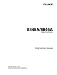
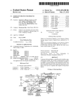
To check or replace the fuse, refer to Figure 2-1 and proceed as follows:
1. Disconnect line power.
2-3
5080A
Operators Manual
2. Open the fuse compartment by inserting a screwdriver blade in the tab located at the
left side of the compartment and gently pry until it can be removed with the fingers.
3. Remove the fuse from the compartment for replacement or verification. Be sure the
correct fuse is installed.
4. Reinstall the fuse compartment by pushing it back into place until the tab locks.
Selecting Line Voltage
The Calibrator arrives from the factory configured for the line voltage normally
appropriate for the country of purchase, or as specified at the time of your purchase order.
You can operate the 5080A Calibrator from one of four line voltage settings: 100 V, 120
V, 220 V, and 240 V (47 Hz to 63 Hz). To check the line voltage setting, note the voltage
setting visible through the window in the power line fuse compartment cover (Figure 21). The allowed line voltage variation is 10% above or below the line voltage setting.
To change the line voltage setting, complete the following procedure:
1. Disconnect line power.
2. Open the fuse compartment by inserting a screwdriver blade in the tab located at the
left side of the compartment and gently pry until it can be removed with the fingers.
3. Remove the line voltage selector assembly by gripping the line voltage indicator tab
with pliers and pulling it straight out of its connector.
4. Rotate the line voltage selector assembly to the desired voltage and reinsert.
5. Verify the appropriate fuse for the selected line voltage (100 V/120 V, use 5 A/250 V
slow blow; 220 V/240 V, use 2.5 A/250 V slow blow) and reinstall the fuse
compartment by pushing it back into place until the tab locks.
Connecting to Line Power
XW Warning
To avoid shock hazard, connect the factory supplied threeconductor line power cord to a properly grounded power outlet.
Do not use a two-conductor adapter or extension cord. This will
break the protective ground connection.
If there is any question about the effectiveness of instrument
earth grounding through the line power cord ground wire, use
the rear-panel AUX EARTH GROUND terminal for a protective
grounding wire.
The Calibrator is shipped with the appropriate line power plug for the country of
purchase. If you need a different type, refer to Table 2-2 and Figure 2-2 for a list and
illustration of the line power plug types available from Fluke.
After you verify the line voltage selection is set correctly and the correct fuse for the
selected line voltage is installed, connect the Calibrator to a properly grounded threeprong outlet.
Selecting Line Frequency
The Calibrator is shipped from the factory for nominal operation at 60 Hz line frequency.
If you are using 50 Hz line voltage, you should re-configure the 5080A for optimal
performance at 50 Hz. To do so from the front panel, go to SETUP, INSTMT SETUP,
OTHER SETUP, and then select MAINS 50 HZ to “on”. Store the change. After the
instrument is warmed up (on for 30 minutes or longer), you must re-zero the complete
instrument. For details, see “Zeroing the Calibrator” in Chapter 4.
2-4
Operation Preparation
Selecting Line Frequency
2
M
AI
N
S
SU
10
0
PP
22 V /
LY
0V 12
/ 2 0V
40
V
FU
SE
T5
.
T2 0A
.5 25
A 0V
25 (
0V SB
(S )
B)
C
A
R U
E T
O PL IO
F A N
IN CE
F
D
IC ON OR
AT L F
EDY W IR
E
R IT P
AT H R
IN A 2OT
G 5 EC
0V T
FUION
SE
LINE VOLTAGE
INDICATOR
CHANGING LINE FUSE
0V
(S
B)
12
0
0
4
2
12
0
CHANGING LINE VOLTAGE
Figure 2-1. Fuse Access and Line Voltage Selection
nn007f.eps
2-5
5080A
Operators Manual
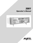
Table 2-2. Line Power Cord Types Available from Fluke
Type
Voltage/Current
Fluke Option Number
LC-1
LC-2
LC-3
LC-4
LC-5
LC-6
LC-7
120 V/15 A
240 V/15 A
220 V/16 A
240 V/13 A
220 V/10 A
240 V/10 A
240 V/5 A
North America
North America
Universal Euro
United Kingdom
Switzerland
Australia
South Africa
LC-1
LC-2
LC-5
LC-3
LC-6
LC-4
LC-7
Figure 2-2. Line Power Cord Types Available from Fluke
nn008f.eps
Service Information
Each Model 5080A Calibrator is warranted to the original purchaser for a period of 1
year beginning on the date received. The warranty is located at the front of this manual.
To locate an authorized service center, call Fluke using any of the phone numbers listed
below, or visit us on the World Wide Web: www.fluke.com.
USA:
Technical Support: 1-888-99-FLUKE (1-888-993-5853)
Calibration/Repair: 1-888-99-FLUKE(1-888-993-5853)
Canada: 1-800-36-FLUKE (1-800-363-5853)
China: +86-400-810-3435
Europe: +31 402-678-200
Japan: +81-3-3434-0181
Singapore: +65-738-5655
Anywhere in the world: +1-425-446-5500
After-warranty service is available, but you may choose to repair the Calibrator using the
information in the Troubleshooting Chapter of the 5080A Service Manual and the
Module Exchange Program. Refer to the Fluke catalog or contact a Fluke Service Center
representative for the module exchange procedure.
2-6
Operation Preparation
Cooling Considerations
2
Cooling Considerations
W Warning
To avoid risk of injury, never operate or power the Calibrator
without the fan filter in place.
W Caution
Damage caused by overheating may occur if the area around
the air intake or exhaust is restricted, the intake air is too warm,
or the air filter becomes clogged.
Baffles direct cooling air from the fan through the chassis to dissipate heat during
operation. The accuracy and dependability of all internal parts of the Calibrator are
enhanced by maintaining the coolest possible internal temperature. You can lengthen the
life of the Calibrator and enhance its performance by observing the following rules:
•
The area around the air filter must be at least 3 inches from nearby walls or rack
enclosures.
•
The exhaust perforations on the sides of the Calibrator must be clear of obstructions.
•
The air entering the instrument must be at room temperature. Make sure the exhaust
air from another instrument is not directed into the fan inlet.
•
Clean the air filter every 30 days, or more frequently if the Calibrator is operated in a
dusty environment. (See Chapter 7, “Maintenance” for instructions on cleaning the
air filter.)
2-7
5080A
Operators Manual
Accessories and Options
Table 2-3 lists accessories and options available for the Calibrator.
Table 2-3. Accessories and Options
Accessory/Option
5080A Service Manual
Oscilloscope Calibration Option
Fluke Model/
Part Number
3790039
[1]
MegOhm Meter Calibration Option
5080A-SC
[1]
5080A-MEG
Transit Case with Wheels
5080A/CASE
Double Banana Plug Adapter
105825
5 A/250 V Time Delay Fuse (mains fuse for 100 V/120 V line voltage)
109215
2.5 A/250 V Time Delay Fuse (mains fuse for 200 V/240 V line voltage)
851931
4 A/500 V Fuse (AUX current output fuse)
3674001
25 A/250 V Fuse (20A current output fuse)
3470596
RS-232 Interface Cable
RS43
Ethernet Internet Cable
884X-ETH
Calibration Software for Automated Calibration with 5080A
5080/CAL
License disk for MET/CAL. Automated Calibration software. MET/BASE-5 or later
required.
MET/CAL-L
License disk upgrade. MET/BASE-7U and prior version of MET/CAL required.
MET/CAL-LU
Asset Management Software. MET/BASE-5 or later required
MET/TRACK
System engine. Requires licenses for one or more client applications (MET/CAL-L,
and/or MET/TRACK)
MET/BASE
Manual Calibration Software. MET/BASE and MET/TRACK required.
Manual MET/CAL
[1]
Options can be ordered factory installed with a new calibrator (5080A/MEG, 5080A/SC, and 5080A/SC/MEG), or added later at a
Fluke service center for an additional installation and calibration charge.
Rack Mount Considerations
Rack mount the Calibrator using a support shelf or drawer. The Calibrator chassis is not
designed for use with front-mounted rack ears or side-mounted rack slides.
XWWarning
Do not restrict access to the Calibrator power cord, which is the
mains disconnecting device. If access to the power cord is
inhibited by rack mounting, a properly rated accessible
proximate mains disconnecting switch must be provided as
part of the installation.
2-8
Chapter 3
Features
Title
Introduction..........................................................................................................
Front-Panel Features ............................................................................................
Rear-Panel Features .............................................................................................
Softkey Menu Trees.............................................................................................
Page
3-3
3-3
3-3
3-3
3-1
5080A
Operators Manual
3-2
Features
Introduction
3
Introduction
This chapter is a reference for the functions and locations of the 5080A Calibrator's frontand rear-panel features. Please read this information before operating the Calibrator.
Front-panel operating instructions for the Calibrator are provided in Chapter 4, “FrontPanel Operation”; remote operating instructions are provided in Chapter 5, “Remote
Operation.”
Front-Panel Features
Front-panel features (including all controls, displays, indicators, and terminals) are shown
in Figure 3-1. Each front-panel feature is described in Table 3-1.
Rear-Panel Features
Rear-panel features (including all terminals, sockets, and connectors) are shown in Figure
3-2. Each rear-panel feature is described in Table 3-2.
Softkey Menu Trees
The Setup softkeys are identified in Figures 3-3 and 3-4. The Setup softkeys are
associated with the 5080A Calibrator front-panel S key. The functions of the five
softkeys are identified by label information displayed directly above each key. The
softkey labels change during operation so that many different functions are quickly
accessible.
A group of softkey labels is called a menu. A group of interconnected menus is called a
menu tree. Figure 3-3 shows the SETUP menu tree structure. Figure 3-4 describes each
SETUP menu tree display. Table 3-3 shows the factory default settings for the SETUP
menu tree. To return the SETUP menus to their default values, use the softkey SETUP in
the Format NV Memory menu (see Figure 3-4, menu F).
3-3
5080A
Operators Manual
1
3
4
5
2
8
6
9
7
Figure 3-1. Front-Panel View
gew322f.eps
Table 3-1. Front-Panel Features
A
Output Display
The Output Display is a two-line backlit LCD that shows output amplitudes, frequency and
Calibrator status. Output values (or potential output values if in standby) are displayed using up to
six digits plus a polarity sign. Output frequencies (or potential output frequencies if the 5080A is in
standby) are displayed using four digits. Calibrator status is indicated by displaying the following
abbreviations:
B
OPR
Displayed when an output is active at the front-panel terminals.
STBY
Displayed when the 5080A is in standby.
u
When you change the output, a “u” (unsettled) is displayed until the output settles to
within the specified accuracy.
C
Displayed when unstored calibration constants are in use.
Control Display
The Control Display is a multipurpose backlit LCD used for displaying data entries, UUT error
adjustments, softkey labels, phase angles, watts, power factors, and other prompts and messages.
When there isn’t enough room on the Output Display, output frequency is displayed on the Control
Display. Softkey labels identify the function of the softkey directly below them. Several softkey
labels together are called a menu. The changing menus provide access to many different functions
through the five softkeys plus the PREV MENU key. (See Figure 3-3, Softkey Menu Tree.)
3-4
Features
Softkey Menu Trees
3
Table 3-1. Front-Panel Features (cont.)
C
Y
The STBY (Standby) key places the 5080A in standby mode. Standby mode is indicated by
“STBY” in the lower left corner of the Output Display. In standby mode, the NORMAL, AUX and
20A output terminals are internally disconnected from the 5080A. The 5080A starts up in standby
mode. The 5080A automatically switches to standby if one of the following occurs:
The RESET key is pressed.
A voltage ≥ 33 V is selected when the previous output voltage was less than 33 V.
The output function is changed, except when going between ac or dc voltage <33 V. The current
output changes from 20A output to AUX output or from AUX output to 20A output.
The current is changed from ac to dc or from dc to ac.
An overload condition is detected.
D
O
The OPR (Operate) key places the 5080A in operate mode. Operate mode is indicated by “OPR” in
the lower left corner of the Output Display and the lit indicator on the OPR key.
E
Z
The EARTH (Earth Ground) key opens and closes an internal connection between the NORMAL
LO terminal and earth ground. An indicator on the key indicates when this connection is made. The
power-up default condition is earth disabled (indicator off).
F
a
The SCOPE (Oscilloscope) key activates or deactivates an oscilloscope calibration option if it is
installed. An indicator on the key indicates when the option is activated. If an oscilloscope
calibration option is not installed in the Calibrator and the SCOPE key is pressed, the Calibrator
displays an error message.
G
F
The MEG O (Megohm) key activates or deactivate the megohm calibration option if it is installed.
An indicator on the key indicates when the option is activated. If the megohm calibration option is
not installed in the Calibrator and the MEG O key is press, the Calibrator displays an error
message.
H
P
The PREV MENU (Previous Menu) key recalls the previous set of menu choices. Each press of
this key backs up one level of the menu tree until the display indicates the top level menu selection
of the function selected.
I
Softkeys
The functions of the five unlabeled blue softkeys are identified by labels on the Control Display
directly above each key. The functions change during operation so that many different functions
are accessible through these keys. A group of softkey labels is called a menu. A group of
interconnected menus is called a menu tree.
3-5
5080A
Operators Manual
13
11
10
22
21
18
20
12
17
16
14
15
19
Figure 3-1. Front-Panel View (cont.)
gew324f.eps
Table 3-1. Front-Panel Features (cont.)
J
N
The NEW REF (New Reference) key is active during error mode operation, and establishes the
present output value as a new reference for meter error computation.
K
S
The SETUP (Setup Menu) key puts the 5080A in the setup mode, displaying the setup menu in the
Control Display. Setup options can be selected using the softkeys under the Control Display.
L
R
The RESET (Reset Calibrator) key aborts the current operating state of the 5080A and returns it to
the power-up default state, except when operating under remote control.
M
G
The CE (Clear Entry) key clears a partially completed keypad entry from the Control Display. If
there is a partially completed entry when CE is pressed, the output is unaffected.
N
LeW
The EDIT FIELD (Edit Output Display Field) key and associated left/right arrow keys provide step
adjustment of the output signals. If any of these keys are pressed or the knob is rotated, a digit on
the Output Display becomes highlighted and the output increments or decrements as the knob is
rotated. If a digit rolls past 0 or 9, the digit to its left or right is carried. An error display appears on
the Control Display, showing the difference between the original (reference) output and the new
output.
The L and W keys adjust the magnitude of changes by moving the highlighted digit. The e
key allows you to move from voltage or current to frequency and back. In practice, for voltage and
current outputs, the knob and arrow keys are used to adjust output until the UUT reads correctly.
The error display then displays UUT deviation from the reference.
O
3-6
The power switch turns the power on and off. The switch is a latching push-push type. When the
switch is latched in, power is on.
Features
Softkey Menu Trees
3
Table 3-1. Front-Panel Features (cont.)
P
D
The divide by 10 key immediately changes the output to 1/10th reference value (not necessarily the
present output value) if the value is within performance limits.
Q
X
The multiply by 10 key immediately changes the output to 10X the reference value (not
necessarily the present output value) if the value is within performance limits. This key sets the
5080A to standby if this change is from a value <33 V to a value ≥33 V.
R
E
The ENTER key loads a newly entered output value shown on the Control Display into the 5080A,
which appears on the Output Display. The new value can come from the numeric keypad. If you
press ENTER without identifying the units for the entry, in most cases the 5080A keeps the units
that were last used. This allows you, for example, to enter 1 mV, and then later enter 10 to obtain
10 V. (The "V" units were saved from the last entry, but not the multiplier, "m".) In the Error (edit)
mode, ENTER with no value restores the output to the value of the reference.
S
Output Units Keys
The output units keys determine the function of the 5080A. Some keys have a second unit if the
SHIFT key is pressed just before the units key. The output units are as follows:
V
Volts or Decibels relative to 1 mW into 600 ohms
(impedance changeable).
A
Watts or amperes
Q
Ohms
H
Frequency or seconds
When a non-zero frequency (Hz) value is entered, the 5080A automatically switches to ac. When a
new signed (+ or −) output value is entered without specifying Hz, the 5080A automatically
switches back to dc (or enter “0” Hz to move back to volts dc).
T
b
The SHIFT key selects alternate functions of the units keys and alternate multipliers of the
multiplier keys. These alternate selections are labeled with small letters in the upper left hand
corner of the keys.
U
Multiplier Keys
Select output value multipliers. Some keys have a second function if the SHIFT key is pressed just
before the multiplier key. For example, if you enter 33, then SHIFT, then c, then V, then
ENTER, the 5080A output value is 33 μV. The multiplier keys are as follows:
V
c
-3
-6
milli (10 or 0.001) or micro (10 or 0.000001)
K
3
-9
kilo (10 or 1,000) or nano (10 or 0.000000001)
M
6
9
mega (10 or 1,000,000) or giga (10 or 1,000,000,000)
Numeric Keypad
Used to enter the digits of the output amplitude and frequency. The proper sequence to enter a
value is to press the digits of the output value, a multiplier key (if necessary), an output units key,
then ENTER. For example, to obtain an output of 20 mV, press the following sequence of keys:
2, 0, c, and V. Press O to enable the output. Pressing a digit key once the entry field is
full, or pressing the decimal point key more than once in a single number, will sound the beeper.
3-7
5080A
Operators Manual
26
28
27
29
25
24
23
Figure 3-1. Front-Panel View (cont.)
gew325f.eps
Table 3-1. Front-Panel Features (cont.)
W
I
The I (Polarity) key changes the polarity of the output for dc voltage or dc current functions.
Press the I key then E to toggle the output polarity.
3-8
X
The MegOhm terminals are used for high resistance sourcing. This button is active only when a
MegOhm option is installed.
Y
The SCOPE TRIG (Scope Trigger) BNC connector is used to trigger the oscilloscope during
oscilloscope calibration. This is active only when an oscilloscope option is installed.
Z
The SCOPE OUT (Oscilloscope) BNC connector is used for outputs during oscilloscope
calibration. This is active only when an oscilloscope calibration option is installed.
a
The 20A terminal is the source of current output when the 20 A range is selected (3 A - 20 A).
b
The AUX (Auxiliary Output) terminals are used for ac and dc current outputs, the second voltage
output in dual voltage modes, and ohms sense for 2-wire and 4-wire compensated resistance.
c
The NORMAL (Normal Output) terminals are used for ac and dc voltage, ohms.
Features
Softkey Menu Trees
1
8
7
2
6
Figure 3-2. Rear-Panel View
3
3
4
5
gew323.eps
Table 3-2. Rear-Panel Features
A
The Fan Filter covers the air intake to keep dust and debris out of the chassis air baffles. The
5080A fan provides a constant cooling air flow throughout the chassis. Instructions for fan filter
maintenance are in Chapter 7, Maintenance.
B
C
Service use only.
D
E
Calibration switch.
F
Service use only.
The RS-232 Port provides a communication channel that allows the Calibrator to be controlled by
sending it commands.
The Ethernet Port provides a communication channel that allows the Calibrator to be controlled by
sending it commands.
3-9
5080A
Operators Manual
Table 3-2. Rear-Panel Features (cont.)
G
XW Warning
To avoid shock hazard, connect the factory supplied
three-conductor line power cord to a properly grounded
power outlet. Do not use a two-conductor adapter or
extension cord; this will break the protective ground
connection.
If there is any question about the effectiveness of
instrument earth grounding through the line power cord
ground wire, use the rear-panel AUX EARTH GROUND
terminal for a protective grounding wire.
The AUX EARTH GROUND terminal is internally grounded to the chassis. If the 5080A is the
location of the ground reference point in a system, this binding post can be used for connecting
other instruments to earth ground. Refer to “Connecting the Calibrator to a UUT” in Chapter 4,
“Front-Panel Operation” for details.
H
3-10
The AC Power Input Module provides a grounded three-prong connector that accepts the line
power cord, a switch mechanism to select the operating line voltage, and a line power fuse. See
Chapter 2, “Preparing for Operation” for information on selecting the operating line voltage, and
fuse rating and replacement information.
Features
Softkey Menu Trees
SETUP
3
Front Panel Key
A
W
X
B
Y
F
Z
C
AC
E
AH
D
AF
AG
AD
G
AE
AM
AJ
G1
AF
AK AL
AA
AH
AB
AF
H
P
R
I
Q
K
I1
S
L
T
M
U
N
V
Figure 3-3. SETUP Softkey Menu Tree
gew013f.eps
3-11
5080A
Operators Manual
A
to X
W
to G
to B
SHOW SPECS is an online summary of the programmed output specifications.
B
to AG
to F
to C
If self test does not pass, error codes are displayed. (See chapter 7, "Maintenance")
C
to E
to D
SERIAL # displays the serial number of the instrument. When corresponding with the factory,
always include the serial number of the instrument.
D
USER REPORT STRING CONTENTS refer to a string of characters entered by the user for
reporting purposes.
Figure 3-4. SETUP Softkey Menu Displays
3-12
gew014.eps
Features
Softkey Menu Trees
3
E
Actual revision numbers may be different for each of the above.
F
Format NV (non-volatile) Memory should be used with caution. Changes are non-reversible. The
softkeys function only when the rear-panel CALIBRATION switch is set to ENABLE, except for the
softkey SETUP, which is not dependent on the CALIBRATION switch position.
All sets all calibration and setup constants to factory setting. CAL set only calibration constants
to factory settings. SETUP resets instrument setup to factory default settings (see Table 3-3).
G
to S
to P
to H
to K
to I
G1
H
HOST selects the Ethernet port or RS-232 (factory default) port. You cannot operate both Ethernet
and RS-232 simultaneously.
gew015.eps
Figure 3-4. SETUP Softkey Menu Displays (cont.)
3-13
5080A
Operators Manual
I
to I1
I1
K
to L
STALL refers to the method of controlling data flow: software control (xon/off), hardware control
(rts/cts) or none.
L
to M
REMOTE I/F (Interface) has selections term (terminal) and comp (computer) (factory default). EOL
(End of Line character) is either Carriage Return/Line Feed (CRLF), CR (Carriage Return) or LF
(Line Feed).
Figure 3-4. SETUP Softkey Menu Displays (cont.)
3-14
gew016.eps
Features
Softkey Menu Trees
3
M
to N
to K
EOF (End of File) indicates the action taken at the end of a file by entering one or two ASCII
characters.
N
EOF (End of File) ASCII characters are entered with a range of 000 to 255 (first character) and 000
to 255 (second character). The factory defaults are 012,000, where the FF (form feed) character
signals an advance to the next page, and the NULL (ignore) character holds position. When the
NULL character is 000 (^@), then effectively the EOF is only the FF character, or ^L for the factory.
P
CHINESE
to R
to Q
DISPLAY BRIGHTNESS and DISPLAY CONTRAST apply to both the Output Display and Control
Display.
Q
levels 0,1,2,3,4,5,6,7
levels 0,1,2,3,4,5,6,7
There are eight levels of contrast, 0 to 7, for the Output Display and Control Display. Each may
have its own level of contrast. The factory defaults are 3 and 7.
Figure 3-4. SETUP Softkey Menu Displays (cont.)
gew017.eps
3-15
5080A
Operators Manual
R
levels 0,1,2,3,4,5,6,7
levels 0,1,2,3,4,5,6,7
There are eight levels of brightness, 0 to 7, for the Output Display and Control Display. Each may
have its own level of contrast. The factory defaults are 1 and 2.
S
to T
T
to V
to U
The values set here become the new limits and can be changed only with new entries or
returned to factory defaults using Format NV Memory SETUP (see menu F).
U
Figure 3-4. SETUP Softkey Menu Displays (cont.)
3-16
gew018.eps
Features
Softkey Menu Trees
3
V
W
SHOW SPECS is an online summary of the programmed output specifications.
X
to Y
to AC
to AA
Select the desired CAL (Calibration) feature: CAL to calibrate the 5080A (see the Service
Manual); CAL DATES to review when the 5080A Calibrator was last calibrated; REPORT
SETUP to configure calibration reports; PRINT REPORTS to print calibration data.
Y
to Z if options are installed
Z
to X
AA
to AB
Figure 3-4. SETUP Softkey Menu Displays (cont.)
gew020.eps
3-17
5080A
Operators Manual
AB
AC
(Only if an
option installed)
to AE
to AD
5080A CAL opens the calibration menu. Refer to the Service Manual for instructions.
ZERO zeros the 5080A Calibrator. ERR ACT (Error Action) set backup, abort, or cont (continue).
AD
to AF
GO ON and ABORT softkeys are used in the 5080A Calibrator calibration procedure. See the
Service Manual for more information.
AE
to AM
AF
Figure 3-4. SETUP Softkey Menu Displays (cont.)
3-18
gew021.eps
Features
Softkey Menu Trees
3
AG
to AH
to AJ
AH
AJ
to AK
to AL
AK
AL
(Only if option
installed)
AM
to AF
Figure 3-4. SETUP Softkey Menu Displays (cont.)
gew022.eps
3-19
5080A
Operators Manual
Table 3-3. Factory Defaults for SETUP Menus Power-Up Defaults
Parameter
Setup from Figure 3-4
User report string (*PUD string)
Cleared
D
Error units
>0.1 %
G1
Host interface
RS-232
H
Host serial interface
comp, 8 bits, 1 stop bit, xon/xoff,
parity none, 9600 baud, CRLF,
012,000
K, L, M, N
Display brightness [1]
level 1,2
P
Display contrast [1]
level 3,7
P
dBm impedance
600 Ω
S
Current limits
±20.5 A
U
Voltage limits
±1020 V
V
[1]
3-20
Setting
Output display and control display, respectively. There are 8 levels: 0, 1, 2, 3, 4, 5, 6, 7.
Chapter 4
Front-Panel Operations
Title
Introduction..........................................................................................................
Turning on the Calibrator.....................................................................................
Warming up the Calibrator ..................................................................................
Using the Softkeys ...............................................................................................
Using the Setup Menu..........................................................................................
Using the Instrument Setup Menu ...................................................................
Utility Functions Menu....................................................................................
Using the Format NV Memory Menu .............................................................
Resetting the Calibrator .......................................................................................
Zeroing the Calibrator..........................................................................................
Using the Operate and Standby Modes................................................................
Connecting the Calibrator to a UUT....................................................................
Recommended Cable and Connector Types....................................................
When to Use EARTH ......................................................................................
Four-Wire versus Two-Wire Connections ......................................................
Cable Connection Instructions.........................................................................
Auto Range Versus Locked Range ......................................................................
Setting the Output ................................................................................................
Setting DC Voltage Output .............................................................................
Setting AC Voltage Output .............................................................................
Setting DC Current Output..............................................................................
Setting AC Current Output..............................................................................
Setting DC Power Output................................................................................
Setting AC Power Output................................................................................
Setting a Dual DC Voltage Output ..................................................................
Setting a Dual AC Voltage Output ..................................................................
Setting Resistance Output................................................................................
Sine Wave Output................................................................................................
Adjusting the Phase .............................................................................................
Entering a Phase Angle ...................................................................................
Entering a Power Factor ..................................................................................
Editing and Error Output Settings........................................................................
Editing the Output Setting ...............................................................................
Displaying the UUT Error: AC and DC Voltage and Current Output.............
Displaying the UUT Error: Resistance Output................................................
Using Multiply and Divide..............................................................................
Setting Voltage and Current Limits .....................................................................
Page
4-3
4-3
4-4
4-4
4-4
4-5
4-5
4-6
4-6
4-6
4-7
4-8
4-8
4-9
4-9
4-10
4-12
4-13
4-13
4-14
4-16
4-17
4-18
4-20
4-22
4-24
4-27
4-28
4-29
4-30
4-31
4-31
4-32
4-32
4-33
4-33
4-33
4-1
5080A
Operators Manual
4-2
Front-Panel Operations
Introduction
4
Introduction
XW Warning
The 5080A Calibrator is capable of supplying lethal voltages. To
avoid shock hazard, do not make connections to the output
terminals when any voltage is present. Placing the instrument
in standby may not be enough to avoid shock hazard, since the
O key could be pressed accidentally. Press the R key and
verify that the 5080A Calibrator is in standby before making
connections to the output terminals.
This chapter presents instructions for operating the 5080A Calibrator from the front
panel. For a description of front-panel controls, displays, and terminals, see Chapter 3,
“Features.”
Turning on the Calibrator
WW Warning
To avoid electric shock, make sure the 5080A Calibrator is
safely grounded as described in Chapter 2.
W Caution
Before turning the 5080A Calibrator on, make sure that the line
voltage selection is set properly. Refer to “Selecting Line
Voltage” in Chapter 2 to check the line voltage setting.
When the 5080A Calibrator is powered, the initial display is “Starting Up...” (see below)
and it completes a self-test routine. If a self-test fails, the Control Display identifies an
error code. For a description of error codes, see Chapter 7, “Maintenance.”
nn062f.eps
After self-test, the control display shows the reset condition (below).
nn063f.eps
For a discussion of the softkey selection shown above (auto/locked), see “Auto Range
Versus Locked Range” later in this chapter.
4-3
5080A
Operators Manual
Warming up the Calibrator
When you turn on the 5080A, allow a warm-up period of at least 30 minutes for the
internal components to stabilize. This ensures that the calibrator meets or exceeds the
specifications listed in Chapter 1.
If you turn the 5080A Calibrator off after warm-up and then on again, allow a warm-up
period of at least twice the length of time it was turned off (maximum of 30 minutes). For
example, if the calibrator is turned off for 10 minutes and then on again, allow a warm-up
period of at least 20 minutes.
Using the Softkeys
The five keys just to the right of the P (Previous Menu) key are called softkeys.
Softkey key functions are based on the label that appears directly above the key in the
Control Display. Pressing a softkey either changes a value or causes a submenu with new
selections to appear on the Control Display. Softkey menus are arranged in varying
levels, as described in “Softkey Menu Tree” in Chapter 3. You can move backwards to
previous menu selections by repeatedly pressing P. Although pressing R will also
return you to the top level menu, it will also reset all volatile settings and return the
5080A Calibrator to 0 V dc in the standby mode. Use the P key as your main
navigating tool for moving around the menu levels.
Using the Setup Menu
Press the front-panel S key for access to various operations and changeable
parameters. Most parameters are nonvolatile, meaning they will be saved during reset or
when power is turned off. Chapter 3 shows a map of the menu tree, lists the parameters,
and has a table of factory default settings.
When you press S from the power-up state, the display changes as follows:
gew064f.eps
This is the primary instrument setup menu. The list below describes submenus available
through each softkey and tells you where you can find further information in the manuals.
4-4
•
CAL (Calibration) Opens the calibration menu. You use softkeys in this menu to
view the calibration dates, print a calibration report, and perform 5080A calibration,
and to run the Zero calibration routine. Zero calibration is described later in this
chapter.
•
SHOW SPECS (Show Specifications) Displays published 5080A Calibrator
specifications for the output value that is currently selected.
•
INSTMT SETUP (Instrument Setup) Lets you change the power-up or reset default
setting for various instrument parameters. Many of the same parameters in this menu
can be changed during operation, but the changes you make during operation are
volatile. Changing them here makes them nonvolatile. To restore factory defaults,
use the Format NV Memory menu under the UTILITY FUNCTNS menu.
Front-Panel Operations
Using the Setup Menu
•
4
UTILITY FUNCTNS (Utility Functions) Allows you to initiate self-tests, format the
nonvolatile memory (restore factory default settings), and review the instrument
configuration software versions and user report string. These features are explained
under “Utilities Function Menu” later in this chapter.
Using the Instrument Setup Menu
The softkeys in the instrument setup menu (accessed by pressing INSTMT SETUP
softkey in the Setup Menu) are shown below.
nn065f.eps
The list below describes submenus accessed by each softkey.
•
OTHER SETUP Opens a menu that lets you set the clock, and displayed error units.
•
OUTPUT SETUP Opens a menu to change the power-up and reset defaults for
current and voltage output limits and impedance for dBm display.
•
DISPLAY SETUP Opens submenus to set the brightness and contrast of both the
Control Display and Output Display and select the displayed front-panel language.
•
REMOTE SETUP Allows you to change the configuration of the RS-232 port or
Ethernet port. (See Chapter 5, “Remote Operation” for more information.)
Utility Functions Menu
The Setup Menu softkey labeled UTILITY FUNCTNS (Utility Functions) provides
access to Self Test, Format Nonvolatile Memory, and Instrument Configuration.
nn066f.eps
•
SELF TEST This softkey opens a menu with calibrator self-test choices.
•
FORMAT NV MEM (Format Nonvolatile Memory) Opens a menu to restore all or
part of the data in the nonvolatile memory to factory defaults.
•
INSTMT CONFIG (Instrument Configuration) Allows you to view the versions of
software installed in the calibrator as well as the user-entered report string.
4-5
5080A
Operators Manual
Using the Format NV Memory Menu
W Caution
Use with extreme care. The format nonvolatile memory menu
softkeys permanently erase calibration constants. Pressing
ALL or CAL invalidates the state of calibration of the 5080A.
Pressing FORMAT NV MEM in the utility functions menu opens the following:
nn067f.eps
All the softkeys in this menu require the rear-panel CALIBRATION switch to be in the
ENABLE position. The nonvolatile memory contains calibration constants and dates,
setup parameters, and the user report string. In the case of calibration constants, factory
defaults are the same for all Calibrators. They are not the calibration constants obtained
when the 5080A was calibrated by the factory before shipment. The softkeys are:
•
ALL replaces the entire contents of the NV memory with factory defaults. This
would be used by service personnel after replacing the NV flash memory, for
example. It is not required in normal use.
•
CAL replaces all calibration constants with factory defaults but leaves all the setup
parameters unchanged. This is also not required in normal use.
•
SETUP replaces the setup parameters with factory defaults (Table 3-3) but leaves
the state of calibration unchanged. You do not have to break the calibration sticker
for this operation. Remote commands can also change the setup parameters. (See
these commands in Chapter 6: SRQSTR, SPLSTR, *PUD, SP_SET, LIMIT.)
Resetting the Calibrator
At any time during front-panel operation (not remote operation), you can return the
5080A Calibrator to the power-up state by pressing R, except after an error message,
which is cleared by pressing a blue softkey. Pressing the R key does the following:
•
Returns the calibrator to the power-up state: 0 V dc, standby, 330 mV range and all
OUTPUT SETUP menus set to their most recent default values.
•
Clears the stored values for limits and error mode reference.
Zeroing the Calibrator
Zeroing recalibrates internal circuitry, most notably dc offsets in all ranges of operation.
To meet the specifications in Chapter 1, zeroing is required every seven days, or when
the 5080A Calibrator ambient temperature changes by more than 5 °C. The Calibrator
displays a message when it is time to zero the calibrator. Zeroing is particularly important
when your calibration workload has 1 mV resolution, and when there has been a
significant temperature change in the 5080A Calibrator work environment.
Complete the following procedure to zero the calibrator.
Note
The 5080A Calibrator rear-panel CALIBRATION switch does not have to
be enabled for this procedure.
Turn on the Calibrator and allow a warm-up period of at least 30 minutes.
4-6
Front-Panel Operations
Using the Operate and Standby Modes
4
1. Press R.
2. Press S. The setup menu opens (below).
gew064f.eps
3. Press the CAL softkey. The calibration information menu opens (below).
gew069f.eps
4. Press the CAL softkey. The calibration activity menu opens (below). SCOPE CAL
appears as an option if it is installed.
gew070f.eps
5. Press the ZERO softkey to totally zero the 5080A. After the zeroing routine is
complete (several minutes), press R to reset the calibrator.
Using the Operate and Standby Modes
When the OPERATE annunciator is lit and OPR is displayed, the output value and
function shown on the Output Display is active at the selected terminals. When STBY is
displayed in the Output Display, all calibrator outputs are open-circuited. To enable the
operate mode, press O. To place the calibrator in standby, press Y.
If the calibrator is operating and any of the following events occur, the calibrator
automatically goes into the standby mode:
•
The R key is pressed.
•
A voltage ≥ 33 V is selected when the previous output voltage was less than 33 V.
•
Output function is changed between ac or dc voltage when the output voltage is
≥ 33 V; ac or dc current; resistance and any other function.
•
The output location for current is changed from AUX to 20 A, or vice versa.
•
An overload condition is detected.
4-7
5080A
Operators Manual
Connecting the Calibrator to a UUT
WW Warning
The 5080A Calibrator is capable of supplying lethal voltages. Do
not make connections to the output terminals when a voltage is
present. Placing the instrument in standby may not be enough
to avoid shock hazard, since the O key could be pressed
accidentally. Press reset and verify that the STBY annunciator
appears on the Control Display before making connections to
the output terminals.
The outputs labeled NORMAL (HI and LO) are used to source voltage and resistance
outputs. The LO terminal connects to the analog signal ground inside the guard shield.
This signal line may or may not be tied to the guard shield and/or to chassis ground,
depending on the settings of the Z key. See “When to Use EARTH” on the next page
for an explanation of these internal connections.
The outputs labeled AUX (HI and LO) source current and low voltage in the dual voltage
function. These outputs are also used for four-wire or remote sensing in the resistance
function.
When an oscilloscope calibration option is installed, the BNC connectors labeled SCOPE
OUT and TRIG deliver signals for oscilloscope calibration.
Recommended Cable and Connector Types
WW Warning
Using standard banana plugs on the calibrator output will
expose lethal voltages when not completely inserted into a
mating terminal.
To avoid electric shock, use only cables with correct voltage
ratings.
Cables to the calibrator are connected to the NORMAL and AUX terminals. To avoid
errors induced by thermal voltages (thermal EMFs), use connectors and conductors made
of copper or materials that generate small thermal EMFs when joined to copper. Avoid
using nickel-plated connectors. Optimum results can be obtained by using Fluke Model
5440A-7002 Low Thermal EMF Test Leads, which are constructed of well-insulated
copper wire and tellurium copper connectors. See the Accessories and Options section in
Chapter 1.
4-8
Front-Panel Operations
Connecting the Calibrator to a UUT
4
When to Use EARTH
The 5080A Calibrator front-panel NORMAL LO terminal is normally isolated from earth
(chassis) ground. When it is desired to make a connection between the NORMAL LO
terminal and earth ground, press the Z key, lighting the key annunciator.
To avoid ground loops and noise you must have only one earth ground-to-LO terminal
connection in the system. Usually you make all signal ground connections at the UUT
and verify the Z annunciator is off. Generally, Z is on only for ac and dc volts where
the UUT is isolated from earth ground. There must, however, be a safety ground for the
5080A. See “Connecting to Line Power” in Chapter 2. When enabled by the sourced
output, a softkey LOs appears, which allows you to tie or open an internal connection
between the NORMAL LO terminal and AUX LO terminal. When tied and Z is on,
then both LO terminals are tied to chassis ground.
Four-Wire versus Two-Wire Connections
Four-wire and two-wire connections refer to methods of connecting the 5080A to the
UUT to cancel out test lead resistance to assure the highest precision of the calibration
output. Figures 4-2 through 4-3 illustrate the connection configurations for resistance;
Part of the setting up the calibrator output for resistance includes selections for four-wire
compensation (COMP 4-wire), two-wire compensation (COMP 2-wire) and two-wire no
compensation (COMP off). (See “Setting Resistance Output” later in this chapter.)
Four-Wire Connection – The four-wire connection is typical for calibrating laboratory
measurement equipment. Increased precision is provided for resistance values at or below
190 kΩ. For other values, the lead resistances do not degrade the calibration and the
Calibrator changes the compensation to off (COMP off).
Two-Wire Compensation – The two-wire connection is typical for calibrating precision
handheld Digital Multimeters (DMMs) with a two-wire input. Increased precision is
provided for resistance values at or below 190 kΩ. For other values, the Calibrator
changes the compensation to off (COMP off).
Compensation Off – Compensation off is a typical connection for calibrating handheld
analog meters or DMMs with a two-wire input. This connection is used for all values of
resistance and is usually selected when the analog meter or DMM level of accuracy does
not require the additional precision. This is the default condition whenever an ohms
output is made, following an output that was not ohms.
4-9
5080A
Operators Manual
Cable Connection Instructions
Table 4-1 indicates a figure reference for each type of connection between a UUT and the
5080A Calibrator, referencing Figures 4-1 through 4-5.
To connect the calibrator to a UUT, proceed as follows:
1. If the calibrator is turned on, press R to remove the output from the calibrator
terminals.
2. Make the connections to the UUT by selecting the appropriate figure from Table 4-1.
Table 4-1. UUT Connections
5080A Output
Figure Reference
4-1 Resistance – four-wire compensated
4-2 Resistance - two-wire compensated
4-3 Resistance - compensation off
4-4 DC Voltage/AC Voltage
4-4 DC Voltage/AC Voltage
4-5 DC Current/AC Current
4-5 DC Current/AC Current
Resistance
DC Voltage
AC Voltage
DC Current
AC Current
Note: See the discussion under “Four-Wire versus Two-Wire Connections” above.
UUT
INPUT
SENSE
W 4-WIRE
HI
HI
LO
LO
A
SENSE
SOURCE
UUT
5080A
SOURCE
SENSE
Figure 4-1. UUT Connection: Resistance (4-Wire Compensation)
4-10
gew040f.eps
Front-Panel Operations
Connecting the Calibrator to a UUT
87
4
TRUE RMS MULTIMETER
MIN MAX
RANGE
HOLD H
REL
Hz
mV
mA
A
V
mA
V
LO
OFF
COM
mA A
A
V
UUT
5080A
Figure 4-2. UUT Connection: Resistance (2-Wire Compensation)
87
gew041f.eps
TRUE RMS MULTIMETER
MIN MAX
RANGE
REL
HOLD H
Hz
PEAK MIN MAX
mV
mA
A
V
mA
V
OFF
A
mA A
COM
V
UUT
5080A
Figure 4-3. UUT Connection: Resistance (Compensation Off)
gew042f.eps
4-11
5080A
Operators Manual
87
TRUE RMS MULTIMETER
MIN MAX
RANGE
REL
HOLD H
Hz
PEAK MIN MAX
mV
mA
A
V
mA
V
OFF
mA A
A
COM
V
Figure 4-4. UUT Connection: DC Voltage/AC Voltage
87
MIN MAX
gew046f.eps
TRUE RMS MULTIMETER
RANGE
REL
HOLD H
Hz
PEAK MIN MAX
mV
mA
A
V
mA
V
OFF
A
mA A
COM
V
Figure 4-5. UUT Connection: DC Current/AC Current
gew047f.eps
Auto Range Versus Locked Range
A softkey is provided to toggle between the ranging method auto or locked. This feature
is available only for single-output dc volts and dc current outputs.
nn063f.eps
When auto is selected (the default setting), the calibrator automatically selects the range
4-12
Front-Panel Operations
Setting the Output
4
that provides the best output resolution. When locked is selected, the calibrator locks the
selected range and will not change ranges when you are editing the output, or entering
new outputs. Values lower or higher than the locked range are not allowed. The locked
selection is usually made when you do not want range changes that may cause a small
perturbation in the output, e.g., when checking the linearity of a given multimeter range.
Setting the Output
Setting the calibrator output is similar to entering values into a calculator: press the keys
that represent the value you desire and then press a units key to identify which of the
volts, amps, hertz, etc., you want the value to represent. The control display indicates the
value and units you select as you type them into the calibrator. Once you are satisfied
with the value and units, press E. If the output display indicates STBY, press O
to output the selection. The display of a small “u” (unsettled) in the Output Display
indicates the calibrator is allowing for its internal circuitry to settle.
For example, to set the output to 10 V dc, press:
1→ 0 → V → E→ O
To set the output to 20 V ac at 60 Hz, press:
2→ 0 → V → 6 → 0 → H→ E→ O
To change the output to dc, press:
0 → H→ E or I → E
Step-by-step procedures are provided for each output function as follows:
•
dc voltage
•
ac voltage
•
dc current
•
ac current
•
dc power
•
ac power
•
dual dc voltage
•
dual ac voltage
•
resistance
Setting DC Voltage Output
Complete the following procedure to set a dc voltage output at the 5080A front-panel
NORMAL terminals. If you make an entry error, press G to clear the display, then
reenter the value.
W Caution
To avoid damage to the UUT, verify the applied voltage to the
UUT does not exceed the rating of the UUT insulation and the
interconnecting wiring.
1. Press R to clear any output from the 5080A.
2. Connect the UUT as described earlier in this chapter under “Connecting the
Calibrator to a UUT.”
3. Set the UUT to measure dc voltage on the desired range.
4. Press the numeric keys and decimal point key to enter the desired voltage output
4-13
5080A
Operators Manual
(maximum six numeric keys). For example, 123.456.
Note
At voltage outputs of 100 V and above (nominal), you may notice a slight
high-pitched sound. This is normal.
5. Press I to select the polarity of the voltage (default is +).
6. Press a multiplier key, if necessary. For example, press c.
7. Press V.
8. The Control Display now shows the amplitude of your entry. For example,
123.456 mV (below).
nn071f.eps
9. Press E. The calibrator clears your entry from the Control Display and copies
it into the Output Display (below is typical).
nn072f.eps
10. Press O to activate the calibrator output.
A softkey label for range appears on the Control Display in the dc voltage function:
nn063f.eps
•
Range (Operating Range) selects autorange (auto) or lock (locked) for the present
range. When auto (the default setting) is selected, the calibrator automatically selects
the range that provides the best output resolution. When locked is selected, the
calibrator will not change ranges when you are editing the output. The locked
selection is usually made when you do not want range changes that may cause a
small perturbation in the output, e.g., when checking the linearity of a given
multimeter range.
Setting AC Voltage Output
You may select an ac voltage output in volts or as a power output in dBm, where dBm is
10 log(Pout/.001) , where Pout is expressed in watts. The output range is 1 mV to
1020 V. When selecting dBm outputs, the 5080A calculates dBm at a selected impedance
4-14
Front-Panel Operations
Setting the Output
4
level. Based on this, the formula is:
20 log(V) - 10 log(Impedance * .001) = dBm.
Complete the following procedure to set an ac voltage output at the 5080A front-panel
NORMAL terminals. If you make an entry error, press G to clear the display, then
reenter the value.
W Caution
To avoid damage to the UUT, verify the applied voltage to the
UUT does not exceed the rating of the UUT insulation and the
interconnecting wiring.
1. Press R to clear any output from the 5080A.
2. Connect the UUT as described earlier in this chapter under “Connecting the
Calibrator to a UUT.”
3. Set the UUT to measure ac voltage on the desired range.
4. Output in volts Press the numeric keys and decimal point key to enter the desired
voltage output (maximum five numeric keys). For example, 2.4494.
Output in dBm Press the numeric keys and decimal point key to enter the desired
power output (maximum four numeric keys). For example, 10.00. For a power output
less than 1 mW (negative dBm values), press I to append the numeric entry with
the negative (−) symbol.
When you press the dBm key, the right most softkey becomes active. This allows the
dBm value and output impedance to be entered as a unit.
When output is entered in dBm, the Control Display appears as follows:
gew227f.eps
Note
At voltage outputs of 100 V and above (nominal), you may notice a slight
high-pitched sound. This is normal.
5. Press a multiplier key, if necessary. For example, press c.
6. Output in volts. Press V.
Output in dBm. Press b V. Select an impedance for dBm from a list on the
4-15
5080A
Operators Manual
Control Display using the rightmost softkey.
7. The Control Display now shows the amplitude of your entry. For example, 2.4494 V
(below).
nn073f.eps
8. Press the numeric keys and decimal point key to enter the desired frequency output
(maximum five numeric keys). Press a multiplier key, if necessary. For example,
press the kilo multiplier key K. Then press the H key. For example, 983.2 Hz
(below).
nn074f.eps
9. Press E. The calibrator clears your entry from the Control Display and copies
it into the Output Display (below is typical).
nn075f.eps
10. Press O to activate the calibrator output.
Setting DC Current Output
Complete the following procedure to set a dc current output between AUX HI and LO or
AUX 20A and LO, depending on the current level selected. Current greater than ±3 A is
sourced between the AUX 20A and LO terminals. If you make an entry error, press G
to clear the display, then reenter the value.
1. Press R to clear any output from the calibrator.
2. Connect the UUT as described earlier in this chapter under “Connecting the
Calibrator to a UUT.”
3. Set the UUT to measure dc current on the desired range.
4. Press the numeric keys and decimal point key to enter the desired current output
(maximum five numeric keys). For example, 234.56.
5. Press I to select the polarity of the current (default is +).
6. Press a multiplier key, if necessary. For example, press c.
7. Press A.
8. The Control Display now shows the amplitude of your entry. For example,
234.56 mA.
4-16
Front-Panel Operations
Setting the Output
4
nn077f.eps
9. Press E. The calibrator clears your entry from the Control Display and copies
it into the Output Display (below is typical).
nn078f.eps
10. Press O to activate the calibrator output.
A range softkey appears on the Control Display in the dc current function (operating
range). This selects autorange (auto) or lock (locked) for the present range. When auto
(the default setting) is selected, the calibrator automatically selects the range that
provides the best output resolution. When locked is selected, the calibrator will not
change ranges when you are editing the output. The locked selection is usually made
when you do not want range changes that may cause a small perturbation in the output,
for example, when checking the linearity of a given multimeter range.
Another softkey appears: OUTPUT. When you select 20 A for this parameter, or you
select a current above 3 A, the calibrator switches to standby, and you must change the
test lead to the 20A terminal and press O to activate the output.
Setting AC Current Output
Complete the following procedure to set an ac current output at the AUX or 20A
terminals. If you make an entry error, press G to clear the display, then reenter the
value.
1. Press R to clear any output from the 5080A.
2. Connect the UUT as described earlier in this chapter under “Connecting the
Calibrator to a UUT.”
3. Set the UUT to measure ac current on the desired range.
4. Press the numeric keys and decimal point key to enter the desired current output
(maximum five numeric keys). For example, 123.45.
5. Press a multiplier key, if necessary. For example, press c.
6. Press A.
7. The Control Display now shows the amplitude of your entry. For example,
123.45 mA (below).
nn079f.eps
8. Press the numeric keys and decimal point key to enter the desired frequency output
4-17
5080A
Operators Manual
(maximum five numeric keys). Then press the H key. For example, 983.2 Hz
(below).
nn080f.eps
9. Press E. The calibrator clears your entry from the Control Display and copies
it into the Output Display (below is typical).
nn081f.eps
10. Press O to activate the calibrator output.
gew321f.eps
•
LCOMP turns inductive compensation on and off. Inductive compensation is
available for frequencies up to 65 Hz. LCOMP also enables higher compliance
voltages in 33 mA and 330 mA ranges when “on”. See specifications for voltage
limits.
•
OUTPUT shows whether the output is on the AUX or 20A terminals. Outputs 3 A or
above are always on the 20A terminals.
•
WAVE (waveform) always shows the output signal as a sine wave.
Setting DC Power Output
Note
Tie the terminals NORMAL LO and AUX LO together at the UUT or at the
5080A, via the “LO”s softkey selection “tied.”
The calibrator produces a dc power output by sourcing a dc voltage on the NORMAL
outputs and a dc current on the AUX outputs. Complete the following procedure to set a
dc power output. If you make an entry error, press G one or more times to clear the
display, then reenter the value.
W Caution
To avoid damage to the UUT, verify the applied voltage to the
UUT does not exceed the rating of the UUT insulation and the
interconnecting wiring.
1. Press R to clear any output from the 5080A.
4-18
Front-Panel Operations
Setting the Output
4
2. Connect the UUT as described earlier in this chapter under “Connecting the
Calibrator to a UUT” by adapting the voltage and current connections.
3. Set the UUT to measure dc power on the desired range.
4. Press the numeric keys and decimal point key to enter the desired voltage output
(maximum five numeric keys). For example, 123.45.
Note
At voltage outputs of 100 V and above (nominal), you may notice a slight
high-pitched sound. This is normal.
5. Press I to select the polarity of the voltage (default is +).
6. Press a multiplier key, if necessary. For example, press c.
7. Press V.
The Control Display now shows the amplitude of your entry. For example,
123.456 mV (below).
nn071f.eps
8. Press the numeric keys and decimal point key to enter the desired current output
(maximum five numeric keys). For example, 234.56.
9. Press I to select the polarity of the current (default is +).
10. Press a multiplier key, if necessary. For example, press c.
11. Press A.
The Control Display now shows the amplitude of your entries. For example,
123.456 mV and 234.56 mA (below).
nn082f.eps
12. Press E. The calibrator clears your entry from the Control Display and copies
it into the Output Display (below is typical).
nn083f.eps
13. Press O to activate the calibrator output. When changing power output levels, you
must reenter both voltage and current (in either order).
(Enter voltage or current and then a watts entry value using b A. The remaining
volts or current value is calculated and displayed.)
4-19
5080A
Operators Manual
nn322f.eps
•
I OUT selects AUX or 20A terminals. Current outputs 3 A or above are always on
the 20A terminals.
•
“LO”s ties or opens a connection between front-panel NORMAL LO and AUX LO
terminals. The front-panel NORMAL LO and AUX LO terminals must be tied
together either at the UUT or at the 5080A. The default is tied.
Setting AC Power Output
Note
Tie the terminals NORMAL LO and AUX LO together at the UUT, or at the
5080A via the “LO”s softkey selection “tied.” For optimum phase
performance, tie the LO terminals at the UUT. At current levels > 2.2 A, tie
the terminals at the UUT using heavy gauge wire < 10 mΩ resistance.
The calibrator produces an ac power output by sourcing an ac voltage on the NORMAL
outputs and an ac current on the AUX outputs.
See “Setting AC Voltage Output” above for information on selecting an ac voltage output
in dBm; this procedure assumes an ac voltage output in volts.
Complete the following procedure to set an ac power output. If you make an entry error,
press G one or more times to clear the display, then reenter the value.
W Caution
To avoid damage to the UUT, verify the applied voltage to the
UUT does not exceed the rating of the UUT insulation and the
interconnecting wiring.
1. Press R to clear any output from the 5080A.
2. Connect the UUT as described earlier in this chapter under “Connecting the
Calibrator to a UUT.” (Adapt the voltage and current connections to suit your
application.)
3. Set the UUT to measure ac power on the desired range.
4. Press the numeric keys and decimal point key to enter the desired voltage output
(maximum five numeric keys). For example, 123.45.
Note
At voltage outputs of 100 V and above (nominal), you may notice a slight
high-pitched sound. This is normal.
5. Press a multiplier key, if necessary. For example, press c.
6. Press V.
7. The Control Display now shows the amplitude of your voltage entry. For example,
123.45 mV (below).
4-20
Front-Panel Operations
Setting the Output
4
nn084f.eps
8. Press the numeric keys and decimal point key to enter the desired current output
(maximum five numeric keys). For example, 234.56.
9. Press a multiplier key, if necessary. For example, press c.
10. Press A.
11. The Control Display now shows the amplitude of your voltage and current entries.
For example, 123.45 mV and 234.56 mA (below).
nn085f.eps
12. Press the numeric keys and decimal point key to enter the desired frequency output
(maximum five numeric keys). Then press the H key. For example, 983.2 Hz.
13. The Control Display now shows your entries. For example, 123.45 mV and
234.56 mA at 983.2 Hz (below).
nn086f.eps
14. Press E. The calibrator clears your entry from the Control Display and copies
it into the Output Display (below is typical).
nn087f.eps
15. Press O to activate the calibrator output. When changing power output levels, you
must reenter both voltage and current (in either order).
(Enter voltage or current and then a watts entry value using b A. The remaining
volts or current value is calculated and displayed.)
Three softkey labels appear on the Control Display: WAVE MENUS, I OUT (AUX or
20A terminals), and LCOMP (off or on). The Control Display also shows the real power
output for sine waves. Power out is computed as Power = Cosine Φ (Volts x Current)
where Φ is the phase difference between the volts and current waveforms. Cosine Φ is
also known as the Power Factor (PF).
4-21
5080A
Operators Manual
See the
Adjusting the
Phase Section
nn088f.eps
Setting a Dual DC Voltage Output
Note
Tie the terminals NORMAL LO and AUX LO together at the UUT or at the
5080A, via the “LO”s softkey selection “tied.”
The calibrator produces a dual dc voltage output by sourcing one dc voltage on the
NORMAL outputs and a second on the AUX terminals. Complete the following
procedure to set a dual dc voltage output. If you make an entry error, press G one or
more times to clear the display, then reenter the value.
W Caution
To avoid damage to the UUT, verify the applied voltage to the
UUT does not exceed the rating of the UUT insulation and the
interconnecting wiring.
1. Press R to clear any output from the 5080A.
2. Connect the UUT as described earlier in this chapter under “Connecting the
Calibrator to a UUT.”
3. Set the UUT to measure dual dc voltage on the desired range.
4. Press the numeric keys and decimal point key to enter the desired voltage output at
the NORMAL terminals (maximum six numeric keys). For example, 123.456.
5. Press I to select the polarity of the voltage (default is +).
6. Press a multiplier key, if necessary. For example, press c.
7. Press V.
8. The Control Display now shows the amplitude of your entry for the NORMAL
terminals. For example, 123.456 mV (below).
4-22
Front-Panel Operations
Setting the Output
4
nn071f.eps
Note
Voltage on the AUX output is limited to 7.000 V maximum.
9. Press the numeric keys and decimal point key to enter the desired voltage output at
the AUX terminals (maximum five numeric keys). For example, 234.56.
10. Press I to select the polarity of the voltage (default is +).
11. Press a multiplier key, if necessary. For example, press c.
12. Press V.
13. The Control Display now shows the amplitude of your entries for the NORMAL
terminals (upper reading) and AUX terminals (lower reading) (see below).
gew358.eps
14. Press E The calibrator clears your entry from the Control Display and copies
it into the Output Display (below is typical).
gew366.eps
15. Press O to activate the calibrator output.
A softkey labeled “LO”s appears on the Control Display.
gew360.eps
•
“LO”s (Low Potential Output Terminals) The front-panel NORMAL LO and AUX
LO terminals must be tied together either at the UUT or at the 5080A. When the
front-panel NORMAL LO and AUX LO terminals are tied at the UUT, select “open”
with the “LO”s softkey. If the NORMAL LO and AUX LO terminals are not tied at
the UUT, select “tied” with the “LO”s softkey. The default is tied.
4-23
5080A
Operators Manual
Setting a Dual AC Voltage Output
Note
Tie the terminals NORMAL LO and AUX LO together at the UUT or at the
5080A, via the “LO”s softkey selection “tied.”
The calibrator produces a dual ac voltage output by sourcing one ac voltage on the
NORMAL outputs and a second on the AUX terminals.
Complete the following procedure to set a dual ac voltage output. If you make an entry
error, press G one or more times to clear the display, then reenter the value.
W Caution
To avoid damage to the UUT, verify the applied voltage to the
UUT does not exceed the rating of the UUT insulation and the
interconnecting wiring.
1. Press R to clear any output from the 5080A.
2. Connect the UUT as described earlier in this chapter under “Connecting the
Calibrator to a UUT.”
3. Set the UUT to measure dual ac voltage on the desired range.
4. Press the numeric keys and decimal point key to enter the desired voltage output at
the NORMAL terminals (maximum five numeric keys). For example, 123.45.
5. Press a multiplier key, if necessary. For example, press c.
6. Press V.
7. The Control Display now shows the amplitude of your voltage entry. For example,
123.45 mV (below).
nn084f.eps
Note
The AUX output is limited to 5.000 V rms for sine waves.
8. Press the numeric keys and decimal point key to enter the desired voltage output at
the AUX terminals (maximum five numeric keys). For example, 234.56.
9. Press a multiplier key, if necessary. For example, press c.
10. Press V.
11. The Control Display now shows the amplitude of your entries for the NORMAL
terminals (upper reading) and AUX terminals (lower reading) (below is typical).
gew367.eps
12. Press the numeric keys and decimal point key to enter the desired frequency output
4-24
Front-Panel Operations
Setting the Output
4
(maximum five numeric keys). Then press the H key. For example, 983.2 Hz.
13. The Control Display now shows your voltage and frequency entries. For example,
123.45 mV and 234.56 mV at 983.2 Hz (below).
gew361.eps
14. Press E. The calibrator clears your entry from the Control Display and copies
it into the Output Display (below is typical).
gew364.eps
15. Press O to activate the calibrator output.
Two softkey labels appear on the Control Display: V @ NOR,V @ AUX and WAVE
MENUS.
4-25
5080A
Operators Manual
gew362.eps
•
•
4-26
V @ NOR (Voltage at NORMAL Terminals) V @ AUX (Voltage at AUX
Terminals) This is an information-only softkey position and does not have an
associated function. It shows the output function is dual ac voltage.
WAVE MENUS (Waveform Menus) Opens submenus for selecting the type of
waveform, front-panel LO terminal condition, and phase.
• WAVE (waveform) Always shows the output signal as a sine wave.
• AUXWAVE (waveform) Always shows the output signal as a sine wave.
• “LO”s (Low Potential Output Terminals) The front-panel NORMAL LO and
AUX LO terminals must be tied together either at the UUT or at the 5080A.
When the front-panel NORMAL LO and AUX LO terminals are tied at the UUT,
select “open” with the “LO”s softkey. If the NORMAL LO and AUX LO
Front-Panel Operations
Setting the Output
•
4
terminals are not tied at the UUT, select “tied” with the “LO”s softkey. The
default is tied.
auxφNOR (Phase Difference) Selects the phase difference between the
NORMAL and AUX outputs. See “Adjusting the Phase” later in this chapter.
Setting Resistance Output
In the resistance function, the calibrator supplies your choice of 18 standard resistance
values or a short at the output terminals. Table 4-2 lists the 18 standard resistance values
available from the Calibrator.
Table 4-2. Standard Calibrator Resistances
Resistance Value
Resistance Value
1.0 Ω
19 kΩ
1.9 Ω
100 kΩ
10 Ω
190 kΩ
19 Ω
1.0 MΩ
100 Ω
1.9 MΩ
190 Ω
10 MΩ
1.0 kΩ
19 MΩ
1.9 kΩ
100 MΩ
10 kΩ
190 MΩ
To select a resistance output:
1. Make sure the calibrator is in standby. Press Y if necessary.
2. If the UUT is not connected, connect it now as described previously in this chapter
under “Connecting the Calibrator to a UUT.”
3. Set the UUT to read resistance on the appropriate range.
4. Press the numeric keys for one of the 18 resistances in Table 4-2. For example 1.9.
5. Press a multiplier key, if necessary. For example, press K.
6. Press Q.
7. Press E.
8. The Control Display now shows the value of your entry. For example, 1.9 kΩ
(below).
gew363.eps
Note
If you entered a resistance value that is unavailable, an error message is
displayed.
4-27
5080A
Operators Manual
gew356.eps
9. After you specify a valid resistance and press E, the calibrator clears your
entry from the Control Display and shows the characterized (true) resistance value on
the Output Display (below is typical).
gew365.eps
10. Press O to activate the calibrator output.
The softkeys allow selection of three lead-compensation settings.
•
The COMP (Compensation) softkey is only selectable for resistance values of
190 kΩ or lower. It turns on and off internal two-wire lead compensation circuitry or
selects 4-wire compensation. See “Four-Wire versus Two-Wire Connections” earlier
in this chapter for more information.
In the resistance function, two features are available to enhance accuracy: four-wire
sensing and two-wire compensation. Two-wire compensation works with either a twowire connection or a four-wire connection to a two-wire ohmmeter. A full explanation
follows:
Four-wire connection is available for resistance values 190 kΩ or lower. To activate fourwire resistance, press COMP until 4-wire appears. (Figure 4-1 shows the four-wire
connection.)
For calibrating a meter with a two-wire resistance mode such as a typical handheld
DMM, refer to Figures 4-2 and 4-3. For resistances of 190 kΩ or lower in two-wire
mode, compensation circuitry inside the calibrator is available to remove errors
introduced by resistance in the path between the front-panel terminals and the precision
resistor. This softkey allows you to disable and enable the compensation circuitry. To
activate 2-wire resistance compensation, press COMP until 2-wire appears.
Depending on how you connect the meter, you can use two-wire compensation
referenced at the UUT terminals (Figure 4-2).
Figure 4-3 shows a meter connected in a two-wire connection with the two-wire
compensation circuitry turned off. Use this configuration only if lead resistances are
insignificant. For a two-wire connection, press COMP until off appears..
For resistances where uncompensated lead resistances are significant, use the two-wire
compensation circuit and the connection in Figure 4-2. Use the connection in Figure 4-1
if you want to calibrate the meter referenced at its terminals. Use the connection in Figure
4-3 if you want to calibrate the meter referenced at the ends of its test leads.
Sine Wave Output
The calibrator has a sine wave output for ac power or dual ac voltage (Figure 4-6). The
variables for the sine wave are amplitude and frequency.
4-28
Front-Panel Operations
Adjusting the Phase
4
Peak
RMS (70% Peak)
Period
Figure 4-6. Sine Wave
nn026f.eps
Adjusting the Phase
When in the dual ac voltage and ac power output modes, you can set the calibrator to
source two signals with adjustable phase difference. All phase adjustments shift the AUX
waveform in relation to the NORMAL waveform. Phase shift adjustments are entered
into the calibrator either as degrees (0 to ±180.00) or as a power factor (PF). A leading or
positive phase shift will cause the AUX waveform to lead the NORMAL waveform; a
lagging or negative phase shift will cause the AUX waveform to lag the NORMAL
waveform.
The softkey PHASE is available after pressing the WAVE MENUS softkey that appears
when outputting dual ac voltages or ac power (shown below for ac power output).
4-29
5080A
Operators Manual
nn110f.eps
Entering a Phase Angle
Complete the following procedure to enter a phase shift in degrees. This procedure
assumes you have already sourced a dual ac voltage or ac power output.
1. Press the softkey WAVE MENUS, opening the waveform menu.
2. Press the softkey PHASE, opening the phase entry menu.
3. Press the numeric keys and decimal point key to enter the desired phase angle
(maximum five numeric keys). For example, 123.45.
4. Press I to select leading (+) or lagging (−) phase shift (default is +).
5. The Control Display now shows the value of your entry. For example, a leading
phase angle of 123.45 degrees (below).
4-30
Front-Panel Operations
Editing and Error Output Settings
4
nn111f.eps
6. Press E. The calibrator clears your entry from the “New phase =” line and
copies it to the “Phase =” line of the Control Display.
7. Press G one or more times to return to previous menus.
Entering a Power Factor
Complete the following procedure to enter a phase shift as a power factor (PF).
PF = Cosine Φ, where Φ is the phase shift. This procedure assumes you have already
sourced a dual ac voltage or ac power output using sine waves as the waveform.
1. Press the softkey WAVE MENUS, opening the waveform menu.
2. Press the softkey PHASE, opening the phase entry menu.
3. Press the softkey SHOW PF, opening the power factor entry menu.
4. Press the decimal point key and numeric keys to enter the desired power factor
(maximum three numeric keys). For example, .678.
5. Press the softkey PF to toggle between a leading (lead) or lagging (lag) power factor
(default is lead).
6. The Control Display now shows the value of your entry. For example, a leading
power factor of .678 (below).
nn112f.eps
7. Press E. The calibrator clears your entry from the “New pf=” line and copies
it to the “Power Factor =” line of the Control Display.
8. Press P one or more times to return to previous menus.
Editing and Error Output Settings
All Calibrator outputs except resistance can be edited using the front-panel Edit Field
knob and associated L, W, and e keys. In addition, multiply X and divide D
keys edit the output by decades. The difference between the original output (reference)
and edited output is displayed as an “error” between the two settings. This allows you to
edit a value to achieve a correct reading at the UUT and thereby calculate an error in ±%
or ppm (parts per million) if it is less than ±1000 ppm. Table 4-3 lists the actions that
cause the Calibrator to exit the error mode and return to the original reference output, or
to output a new reference, as selected.
4-31
5080A
Operators Manual
Table 4-3. Keys That Exit Error Mode
Keys
Action
E
Returns to the previous reference value.
I+E
Establishes a new reference.
A new keypad entry + E
Establishes a new reference.
N
Establishes the present output as a new reference.
X
Sets the Calibrator to ten times the reference value and establishes a
new reference.
D
Sets the Calibrator to one-tenth the reference value and establishes a
new reference.
R
Returns to the power-up state.
Editing the Output Setting
When you initially source an output from the Calibrator, you enter a specific value. For
example, 10.0000 V dc. To edit the output value for voltage and current to suit your
application, turn the front-panel Edit Field knob clockwise to increase the value or
counter-clockwise to decrease the value. (The Edit Field controls will not operate if you
are in any setup function. Press the P key one or more times to exit a setup function.)
To select a higher order digit, use an Edit Field cursor key L or W . The output digit
in edit is always underlined (see below).
nn115f.eps
The momentary display of the letter u in the Output Display when editing during OPR
(Operate) indicates “unsettled,” that is, the Calibrator output is settling with a new value.
Displaying the UUT Error: AC and DC Voltage and Current Output
When you edit the output value, the Control Display shows the difference between the
reference value (the value you originally entered) and the edit value (the value shown in
the Output Display), displaying error difference in parts per million (ppm) or percent (%).
For example, if ERR UNI is set to >100 ppm, the error will be displayed in ppm up to 99
and then the error will change to 0.0100% at 100 ppm. This allows you to edit the output
such that the UUT displays the expected value and thus give an indication of the UUT
accuracy.
nn116f.eps
For example, an edited difference of .0003 volts for an output of 10.0000 V represents
0.0003/10.0000=0.000030, or 30 parts per million. The sign is negative (-30.0 ppm)
because the output necessary to display 10.0000 at the UUT shows the UUT is reading
below the output value. When the reference is negative, the error sign is relative to the
4-32
Front-Panel Operations
Setting Voltage and Current Limits
4
magnitude. For example, if the reference is -10.0000 V and the output display is
-10.0003, the error is -30 ppm.
Displaying the UUT Error: Resistance Output
In the resistance output function, the edit controls produce a display of the UUT error in a
similar way, except the output of the calibrator does not change as you turn the knob.
Instead, a reading on the Control Display changes, allowing you to match it to the reading
on the UUT. As you change the reading, the calibrator computes and displays UUT error.
gew357.eps
Using Multiply and Divide
The Calibrator output value (or reference value if you have edited the output) can be
multiplied by a factor of 10 by pressing the X key. Similarly, the output value (or
reference value if you have edited the output) can be divided a factor of 10 by pressing
the D key. The output will be placed in STBY (Standby) if the multiplied value exceeds
33 V. Press the O key if you wish to continue. This feature is useful for UUTs with
ranges organized in decades.
Setting Voltage and Current Limits
An output limit feature is available to help prevent accidental damage to a UUT from
overcurrent or overvoltage conditions. This feature allows you to preset the maximum
positive and negative allowable voltage or current output. Entry limits you set prevent
any output greater than the limit from being activated by entry through the front-panel
keys or the output adjustment controls. Positive limits for voltage and current set the
limits for ac voltage and current. Your limit selections are saved in the nonvolatile
memory. Voltage limits are expressed as rms values, and any voltage offsets are ignored.
To set voltage and current entry limits, proceed as follows:
1. Press R to clear any output from the Calibrator.
2. Press S. Press the softkey INSTMT SETUP to open the setup submenus.
3. Press the softkey OUTPUT SETUP to open the output setup submenus.
4. Press the softkey SET LIMITS to open the set limits menu (below).
nn117f.eps
5. To Limit Voltage (applies to both dc and ac voltages). Press a softkey under
VOLTAGE to open the voltage limits menu (below).
4-33
5080A
Operators Manual
nn118f.eps
a. Press the “Upper Limit” or the “Lower Limit” softkey, as desired, and enter the
new limit.
b. Press E then P one or more times to return to a previous menu.
6. To Limit Current (applies to both dc and ac currents). Press a softkey under
CURRENT to open the current limits menu (below).
nn119f.eps
a. Press the “Upper Limit” or the “Lower Limit” softkey, as desired, and enter the
new limit.
b. Press E then P one or more times to return to a previous menu.
4-34
Chapter 5
Remote Operations
Title
Introduction..........................................................................................................
Setting up the RS-232 Host Port for Remote Control..........................................
Configuring the Ethernet (LAN) Port ..................................................................
Setting the IP Address .....................................................................................
Selecting Dynamic Host Configuration Protocol (DHCP)..........................
Setting a Static Internet Address .................................................................
Setting the LAN Subnet Mask.........................................................................
Reading the Domain Name .............................................................................
Configuring the Host Name.............................................................................
Reading the MAC Address..............................................................................
Configuring the LAN Default Gateway ..........................................................
Configuring the General Network Socket Port................................................
Establishing an Ethernet Connection ...................................................................
Terminating an Ethernet Connection ...................................................................
Changing Between Remote and Local Operation................................................
Local State .......................................................................................................
Local and Lockout State ..................................................................................
Remote State....................................................................................................
Remote with Lockout State .............................................................................
RS-232 Interface Overview .................................................................................
Using Commands.................................................................................................
Types of Commands........................................................................................
Device-Dependent Commands....................................................................
Common Commands...................................................................................
Query Commands........................................................................................
Compound Commands................................................................................
Coupled Commands ....................................................................................
Overlapped Commands ...............................................................................
Sequential Commands.................................................................................
Commands that Require the Calibration Switch .........................................
Command Syntax ............................................................................................
Parameter Syntax Rules ..............................................................................
Extra Space or Tab Characters ....................................................................
Terminators .................................................................................................
Incoming Character Processing...................................................................
Response Message Syntax ..........................................................................
Checking 5080A Status .......................................................................................
Serial Poll Status Byte (STB) ..........................................................................
Page
5-3
5-4
5-5
5-6
5-6
5-7
5-7
5-7
5-7
5-8
5-8
5-8
5-9
5-9
5-10
5-10
5-10
5-10
5-10
5-11
5-11
5-11
5-11
5-12
5-12
5-12
5-12
5-12
5-13
5-13
5-13
5-13
5-15
5-15
5-15
5-15
5-17
5-17
5-1
5080A
Operators Manual
Master Summary Status ..............................................................................
Service Request Enable Register (SRE)......................................................
Programming the STB and SRE..................................................................
Event Status Register (ESR) .......................................................................
Event Status Enable (ESE) Register............................................................
Bit Assignments for the ESR and ESE........................................................
Programming the ESR and ESE..................................................................
Instrument Status Register (ISR).....................................................................
Instrument Status Change Registers............................................................
Instrument Status Change Enable Registers................................................
Bit Assignments for the ISR, ISCR, and ISCE ...........................................
Programming the ISR, ISCR, and ISCE .....................................................
Output Queue...................................................................................................
Error Queue .....................................................................................................
Input Buffer Operation ....................................................................................
5-2
5-19
5-19
5-19
5-19
5-19
5-20
5-20
5-20
5-20
5-21
5-21
5-22
5-22
5-22
5-22
Remote Operations
Introduction
5
XW Warning
The 5080A Calibrator (hereafter referred to as “The Calibrator”)
can produce voltages up to 1020 V rms and must be
programmed with caution to prevent hazardous voltages from
being produced without sufficient warning to the operator.
Write programs carefully and test them extensively to ensure
safe operation of the Calibrator. Fluke suggests that you
include error-catching routines in your programs. These errorcatching routines will help you identify programming errors that
may cause the Calibrator to behave other than intended. You
can program the Calibrator to cause an SRQSTR when an error
is detected by setting the Service Request Enable (SRE)
register.
Introduction
This chapter describes methods for operating the Calibrator by remote control. Remote
control can be interactive, with the user controlling each step from a terminal, or under
the control of a computer program running the Calibrator in an automated system. The
Calibrator rear panel has two ports for remote operations: An Ethernet port and an RS232 serial port.
RS-232 The serial port connects the PC and Calibrator. You can write your own
computer programs using the command set, or operate the PC as a terminal and enter
individual commands, or you can purchase optional Fluke MET/CAL or 5080/CAL
software for RS-232 system operations. Typical RS-232 remote configurations are shown
in Figure 5-1.
RS-232
Port
COM Port
COM Port
RS-232
Port
UUT
5080A Calibrator
Controller
Figure 5-1. Typical RS-232 Remote Control Connections
gew326.eps
After configuring the Ethernet or RS-232 port for remote operation, you are ready to
begin using the command set. The operation of the command set is described under
“Using Commands” in this chapter. A summary of remote commands is in Chapter 6,
“Remote Commands.”
5-3
5080A
Operators Manual
Setting up the RS-232 Host Port for Remote Control
The Calibrator is fully programmable over an RS-232 link with a PC via the rear-panel
serial port (Figure 5-1). You can enter individual commands from a terminal, write your
own programs using, for example, a Windows-based language such as Visual Basic, or
run optional Windows-based Fluke software such as 5080/CAL or MET/CAL.
The RS-232 cable length for the port should not exceed 15 meters (50 feet), although
longer cable lengths are permitted if the load capacitance measured at a connection point
(including signal terminator) does not exceed 2500 pF.
Complete the following procedure to set up the serial port. The RS-232 parameters you
select here must match the parameters set for the PC COM port. The factory defaults
(shown on the display below) are 9600 baud, 8 data bits, 1 stop bit, and no parity. Other
parameters include flow control, EOL (end-of-line) character, and EOF (end-of-file)
characters.
1. Turn the Calibrator power on. You may operate the Calibrator during warmup, but
specifications are not guaranteed until warmup is complete.
2. Press S on the Calibrator front panel.
3. Negotiate the softkey selections shown below to select the serial port for remote
operation, then continue to step 4.
To Step 4
gew329.eps
4. Negotiate the softkey selections shown below to select the HOST serial port
parameters to match the PC COM parameters. (Individual softkey functions are
discussed in Chapter 3, “Features.”) If operating the port with a computer program
instead of individual commands from a terminal, select Remote I/F comp (factory
default).
5-4
Remote Operations
Configuring the Ethernet (LAN) Port
5
gew328.eps
5. Press P (not E) several times until the message STORE
CHANGES/DISCARD CHANGES appears or, if there were no changes, clear the
display. If you select STORE CHANGES, the serial and host port setting are saved
in the instrument non-volatile memory.
Configuring the Ethernet (LAN) Port
The Calibrator can be remotely controlled through the LAN port on the Calibrator’s rear
panel. To select the LAN port as the remote control port, see the “Selecting the Remote
Interface” section above.
Configuring the LAN port is accomplished through the Instrument Setup function. The
selectable LAN port parameters are: DHCP (Dynamic Host Configuration Protocol), IP
Address, Net mask, Host Name, Mac Address, Gateway, Port number, and Domain.
When setting IP addresses, subnet masks, and default gateways on the Calibrator, keep in
mind they are stored as 32-bit binary numbers and expressed as four 3-digit segments in
dot-notation form. For example, xxx.xxx.xxx.xxx, where xxx is a byte value, is stored as
a 32-bit binary number.
To set the LAN port parameters:
1. Push S.
5-5
5080A
Operators Manual
2. Push the softkey labeled INSTMT SETUP.
3. Push the softkey labeled REMOTE SETUP.
4. Push the softkey labeled LAN SETUP. The LAN parameters are set through the two
softkey menus shown in Figure 5-2.
Figure 5-2. Menus to Set LAN Parameters
gew336.eps
Note
When addressing some LAN addresses, computers will often interpret 0's in
the IP address as OCTAL values. As an example, if you configure your IP
address from the front panel as 129.196.017.023 and then attempt to
establish a connection to the calibrator, you should connect using the IP
address 129.196.17.23. Attempting to establish a connection to
129.196.017.023 may result in a connection request to 129.196.15.19.
Setting the IP Address
An internet (IP) address is required for all internet and TCP/IP communications. If DHCP
is enabled, the Calibrator will use the dynamic address supplied by the DHCP server.
However, if the DHCP server fails to supply the address, or DHCP is disabled, the
currently configured static IP address will be used.
Selecting Dynamic Host Configuration Protocol (DHCP)
Dynamic Host Configuration Protocol (DHCP) is a client-server protocol that eliminates
having to manually set permanent/static IP addresses. The DHCP server provides
configuration parameters (dynamic IP address, subnet mask, and default gateway IP
addresses) which are required for a client to participate in an IP network.
Using DHCP is the easiest way to configure the Calibrator for remote communication
through the LAN interface. DHCP is disabled when the Calibrator is shipped from the
factory. When connected to a network, and the LAN port is enabled, the Calibrator will
try and retrieve the parameters from a DHCP server necessary for communications. If the
parameters can’t be obtained, the Calibrator switches to the parameters that were
manually entered into the Calibrator.
To disable or enable DHCP on the Calibrator:
From the LAN menu, push the softkey labeled DHCP to toggle between on and off. If
DHCP is already enabled, then on will be shown in the softkey label.
5-6
Remote Operations
Configuring the Ethernet (LAN) Port
5
Note
After changing any Ethernet setting (except the socket port), the Calibrator
must be powered off and on again, using the front-panel power switch, to
make the change active.
Setting a Static Internet Address
The Calibrator comes from the factory with 169.254.001.001 in the static IP address
register.
Note
If you are planning to use the Calibrator on a corporate LAN and do not
wish to use DHCP, contact your network administrator for a static IP
address to be used exclusively by your Calibrator. DHCP must be disabled
to set a static IP address.
To change the Calibrator’s static IP Address:
1. From the LAN menu, push the softkey labeled IP ADDRESS.
2. Use the numeric keypad to enter the IP address and then push E.
If you make a mistake entering the IP address, you must press push G.
Note
The IP address is stored in non-volatile memory, and does not change when
power is removed and reapplied to the Calibrator or when the Calibrator
receives an *RST command.
Setting the LAN Subnet Mask
If communication between the host computer and the Calibrator passes through a router
or gateway, and DHCP is disabled, you must set the subnet mask and default gateway
address on both the host computer and the Calibrator. Get the correct subnet mask and
gateway address from your network administrator.
The LAN Subnet Mask is a 32-bit number. This number is represented as four 3-digit
segment numbers on the front-panel display. The default subnet mask set at the factory is
255.255.254.0.
To change the Calibrator’s subnet mask:
1. From the LAN menu, push the softkey labeled NETMASK.
2. Use the numeric keypad to enter the IP address and then push E.
If you make a mistake entering the IP address, you must push P or G and go back to
step 1 to start entering the address again.
The new Subnet Mask will not take effect until the Calibrator has been powered down
and back up again using the front-panel power switch.
Reading the Domain Name
The Domain Name is supplied by the DHCP server and cannot be changed. To read the
domain name:
1. From the LAN menu, push NEXT MENU to show the second LAN menu.
2. Push the softkey labeled DOMAIN NAME.
Configuring the Host Name
The Host Name is the host portion of the domain name, which is translated into an IP
address. The Calibrator’s default host name is “FLUKE-5080A-snxxxx”.
5-7
5080A
Operators Manual
To change the Host Name:
1. From the LAN menu, push the softkey labeled HOST NAME.
2. Push e.
3. Push L and W to position the cursor under a character in the host name shown in
the display.
4. Use the rotary knob to change the character to a letter, number, dash, or space.
Push L and W to move the cursor to another character.
When the characters in the host name are set, push E.
Note
It is not necessary to change all excess characters in a name that is longer
than the new name to a space to remove the extra characters. Put a single
space in place of the first excess character in the old name and then push
E. All characters after the space are automatically removed from
the name.
The new Host Name will not take effect until the Calibrator has been powered down and
back up again using the front-panel power switch.
Reading the MAC Address
The MAC Address is set at the factory and cannot be changed. To read the MAC
Address, push the softkey labeled MAC ADDRESS to show the address.
Configuring the LAN Default Gateway
The default gateway IP address is the IP address of a gateway (router) attached to the
same network as the device. When the Calibrator detects that a host computer is not on
the same network (using the network number), the data is sent through the gateway to
reach the host computer.
The default for the Calibrator is “0” (no gateway, and subnetting is not being used).
To set the LAN Default Gateway address:
1. From the LAN menu, push NEXT MENU to show the second LAN menu.
2. Push the softkey labeled GATEWAY.
3. Use the numeric keypad to enter the gateway IP address and then push E.
If you make a mistake entering the gateway IP address, you must push P or G and
go back to step 1 to start entering the address again.
The new gateway address will not take effect until the Calibrator has been powered down
and back up again using the front-panel power switch.
Configuring the General Network Socket Port
In order to communicate with each other, a host computer and the Calibrator must use the
same socket port number. The default port is 3490. Typically, the default port does not
need to be changed. If the socket port must be changed, enter the Socket Port number
supplied by your network administrator.
To change the Socket Port number:
1. From the LAN menu, push NEXT MENU to show the second LAN menu.
2. Push the softkey labeled PORT.
3. Use the numeric keypad to enter a new port number and push E. The port
number must be between 1024 to 65535.
5-8
Remote Operations
Establishing an Ethernet Connection
5
If you make a mistake entering the port number, you must push P or G and go back
to step 1 to start entering the port number again.
The new Network Socket Port becomes effective immediately.
Note
The Network Socket Port Number is stored in non-volatile memory.
Establishing an Ethernet Connection
The easiest method of establishing an Ethernet connection with the Calibrator is through
the commonly available program: Telnet. Telnet is a client-server protocol, based on
TCP. The Telnet Protocol provides a fairly general, bi-directional, eight-bit byte oriented
communications facility. Telnet is available on all UNIX servers and on most PCs.
Telnet clients typically connect to hosts on socket port 23. The LAN connection to the
Calibrator must be established using the specified Network Socket Port. See the
“Configuring the General Network Socket Port” section above. When the remote
interface port is changed to LAN from the Calibrator’s front panel, a LAN server is
initiated in the Calibrator which listens for client connections on the socket port at the
specified IP address.
To establish a LAN connection to the Calibrator from a computer using either UNIX,
LINUX, or MS-DOS command prompts, perform the following procedure:
1. On the Calibrator’s front panel, change the remote interface port to LAN
2. At the command prompt on the client computer, enter:
telnet <IP Address>
<Socket Port>
Alternatively, if you are using DHCP and would like to connect using the host name
rather than the IP address, from the computer command prompt enter:
telnet <Host Name.Domain Name>
<Socket Port>
As an example, if you know the IP address is 129.196.136.131 and the Socket Port is set
to 3490, enter the following at a command prompt from any client computer:
telnet 129.196.136.131 3490
If you are using DHCP and the host name is FLUKE-5080A-snxxxx and the fully
qualified domain name is FLUKE-5080A-snxxxx.na.flukecorp.com and the Socket Port
is set to 3490, enter the following at the computer command prompt:
telnet FLUKE-5080A-snxxxx.na.flukecorp.com 3490
Once the internal LAN server connects with the client computer, the LAN server will
reject any other connection attempts by other computers and will “tunnel” a channel to
the connected computer. This prevents multiple computers from trying to control the
Calibrator.
Terminating an Ethernet Connection
When you wish to terminate the Ethernet connection, you may do so one of two ways:
1. Change the Calibrator’s remote interface port to something other than LAN
2. Terminate the Telnet session on the client computer
If you have established a LAN connection to the Calibrator using Telnet and change the
remote interface port using the Calibrator’s front panel, the LAN server in the Calibrator
will automatically terminate the Telnet session on the client computer.
On the other hand, you may wish to terminate the Telnet session on the client computer
5-9
5080A
Operators Manual
but maintain the current LAN remote interface port configuration. Client Telnet session
termination can vary from computer to computer, but typically terminating the shell (or
command window in DOS) will terminate the telnet session. When the client terminates
the Telnet session, the LAN server in the Calibrator will go back into listen mode waiting
for a new client to make a LAN connection request.
Changing Between Remote and Local Operation
In addition to local mode (front-panel operation) and remote, the Calibrator can be placed
in a local lockout condition at any time by command of the controller. Combined, the
local, remote, and lockout conditions yield four possible operating states described as
follows.
Local State
The Calibrator responds to local and remote commands. This is normal front-panel
operation. All remote commands are allowed to execute.
Local and Lockout State
Local with lockout is identical to local, except the Calibrator will go into the remote with
lockout state instead of the remote state when it receives a remote command.
Remote State
When the Calibrator is placed in remote, either via RS-232/Ethernet REMOTE
command, it enters the remote state. In the remote state, the Output Display continues to
display the output setting or measurement as in local operation. The Control Display
changes to:
nn325f.eps
The left side of the Control Display shows information regarding the present output
function. However, front-panel operation is restricted to use of the power switch and the
"Go To Local" softkeys. Pressing either of these softkeys, using RS-232/Ethernet to send
the command LOCAL returns the Calibrator to the local state.
Remote with Lockout State
When the Calibrator is placed in lockout, via the remote command, the 5080A frontpanel controls are totally locked out. In remote with lockout, the Control Display changes
to:
gew334f.eps
The left side of the Control Display shows information regarding the present output
function. However, front-panel operation is restricted to use of the power switch. To
return the Calibrator to the local with lockout state, send the RS-232/Ethernet LOCAL
command.
Table 5-1 summarizes the possible Remote/Local state transitions.
5-10
Remote Operations
RS-232 Interface Overview
5
Table 5-1. Operating State Transitions
From
Local
Remote
To
Remote with Lockout
Serial Command
Remote
REMOTE
Local with Lockout
LOCKOUT
Local
Local with Lockout
Front Panel
Go to Local Softkey
LOCAL
Remote with Lockout
LOCKOUT
Local
LOCAL
Remote with Lockout
REMOTE
Local
LOCAL
Local with Lockout
RS-232 Interface Overview
The Calibrator RS-232 port is designed in accordance with EIA (Electronic Industries
Association) standard RS-232. RS-232 is a serial binary data interchange operating from
300 to 115200 baud (selectable), and distances up to 50 feet. The Calibrator rear-panel
serial port is configured as DTE (Data Terminal Equipment). See Appendix B for RS-232
cable and connector information. For detailed information, see the EIA standard RS-232.
Using Commands
Communications between the controller and the Calibrator consists of commands,
queries, and interface messages. Although the commands are based on the 488.2
standard, they can be used on either the RS-232 or Ethernet interface. (For more
information on command structures, see the IEEE 488.2 standard.)
Refer to Chapter 6, “Remote Commands” when you require additional information about
command references used this chapter.
All commands and units may be entered in UPPER or lower case.
There are four specific remote control configurations that use commands, queries and
interface messages: RS-232 Terminal Mode and RS-232 Computer Mode.
RS-232 Terminal Mode The RS-232 terminal mode is an interactive mode where an
operator inputs commands, with immediate returns for requested information (queries)
and interface messages.
RS-232 Computer Mode The RS-232 computer mode is used when the Calibrator is
operated by computer program. In this mode, requested information is returned by query,
and interface messages are queued and returned by command.
Types of Commands
The commands for the Calibrator can be grouped into one or more categories, depending
on how they function. Each category is described below
Device-Dependent Commands
Device-dependent commands are unique to the Calibrator. An example of a devicedependent command is:
OUT 100 V, 1 A, 60 HZ
This command instructs the Calibrator to source 100 watts of ac power.
5-11
5080A
Operators Manual
Common Commands
Common commands are defined by the IEEE 488.2 standard and are common to most
bus devices. Common commands always begin with an * character. An example of a
common command is:
*IDN?
This command instructs the Calibrator to return the instrument identification string.
Query Commands
Query commands request information, which is returned as the command executes, or
placed in a buffer until requested. An example of a query, which always ends with a
question mark, is:
RANGE?
This command returns the Calibrator primary and secondary outputs.
Compound Commands
A compound command is two or more commands in a single command line. For
example, the following two commands could be entered individually,
OUT 1 V, 60 HZ
OPER
With these commands the Calibrator sources 1 V ac at 60 Hz, and then goes into operate,
or they could be combined into a compound command as follows:
OUT 1 V, 60 HZ ; OPER
In the previous commands using a semi-colon as a separator, care must be taken when a
compound command includes any of the coupled commands. (See “Coupled
Commands.”)
Coupled Commands
A coupled command refers to two or more commands that appear in a compound
command (see “Compound Commands”) that perform actions that could interfere with
each other causing a fault. Commands in a compound command are separated by using
the ; character. Compound commands using only coupled commands are not orderdependent.
The coupled commands are:
CUR_POST
DBMZ
OUT
Overlapped Commands
Commands that begin execution but require slightly more time to complete are called
overlapped commands, because they can be overlapped by the next command before they
have completed execution.
5-12
Remote Operations
Using Commands
5
The overlapped commands are:
CUR_POST
LOWS
RANGELCK
DBM
MULT
*RST
DPF
OLDREF
STBY
EARTH
OPER
ZCOMP
INCR
OUT
LCOMP
PHASE
You can use the command *WAI to wait until the overlapped command has completed
execution before executing the next command. For example:
OUT 1 V, 1 A, 60 HZ ; *WAI
You can also use the status commands *OPC and *OPC? to detect completion of
overlapped commands. (See “Checking 5080A Status.”)
Sequential Commands
Commands that execute immediately are called sequential commands.
The majority of the commands are sequential.
Commands that Require the Calibration Switch
The following commands do not work unless the rear-panel CALIBRATION switch is in
the ENABLE position:
CLOCK
(when setting date but not time)
FORMAT ALL
FORMAT CAL
*PUD
Attempting to use any of these commands with the CALIBRATION switch in the
NORMAL position logs an error into the error queue. (Or it returns the error message if
in the RS-232 Terminal Mode.)
Command Syntax
The following syntax rules apply to all the remote commands. Information about syntax
of response messages is also given.
Parameter Syntax Rules
Table lists the units accepted in command pareameters and used in responses. All
commands and units may be entered in UPPER or lower case.
5-13
5080A
Operators Manual
Table 5-2. Units Accepted in Parameters and Used in Responses
Units
HZ
Meaning
Frequency in units of hertz
KHZ
Frequency in units of kilohertz
MHZ
Frequency in units of megahertz
UV
Volts in units of microvolts
MV
Volts in units of millivolts
V
Volts in units of volts
KV
Volts in units of kilovolts
UA
Current in units of microamperes
MA
Current in units of milliamps
A
Current in units of amps
PCT
Percent
PPM
Parts-per-million
DBM
Volts in units of decibels referenced to 1 milliwatt into 600 Ω load
OHM
Resistance in units of ohms
KOHM
Resistance in units of kilohms
MOHM
Resistance in units of megohms
NS
Period in units of nanoseconds
US
Period in units of microseconds
MS
Period in units of milliseconds
S
Period in units of seconds
General Rules The general rules for parameter usage is as follows:
1. When a command has more than one parameter, the parameters must be separated by
commas. For example: OUT 1V, 2A
2. Numeric parameters may have up 15 significant digits and their exponents can be in
the range +/-1.0E+/-20.
3. Including too many or too few parameters causes a command error.
4. Null parameters cause an error, for example, the adjacent commas in OUT 1V, ,2A
5. Expressions, for example 4+2*13, are not allowed as parameters.
6. Binary Block Data can be in one of two forms: Indefinite Length and Definite Length
format (both IEEE-488.2 standards).
Indefinite Length The Indefinite Length format accepts data bytes after the #0 until the
ASCII Line Feed character is received with an EOI signal (for RS-232 just a line
feed or carriage return will terminate the block).
Definite Length The Definite Length format specifies the number of data bytes. The
data bytes are preceded by #n and an n-digit number. The n-digit number identifies
5-14
Remote Operations
Using Commands
5
how many data bytes follow. For examples, see the *PUD command descriptions in
Chapter 6.
Extra Space or Tab Characters
In the command descriptions in Chapter 6, parameters are shown separated by spaces.
One space after a command is required (unless no parameters are required). All other
spaces are optional. Spaces are inserted for clarity in the manual and may be left in or
omitted as desired. You can insert extra spaces or tabs between parameters as desired.
Extra spaces within a parameter are generally not allowed, except for between a number
and its associated multiplier or unit. Chapter 6 contains examples for commands whose
parameters or responses are not self-explanatory.
Terminators
Table 5-3 summarizes the terminator characters for the RS-232 and Ethernet remote
interfaces.
Table 5-3. Terminator Characters
Terminator
ASCII Character
Program
Control Command
Language
Command
Terminator
Terminator
Function
Number
Carriage Return (CR)
13
Chr(13)
<Cntl> M
\n
Line Feed (LF)
10
Chr(10)
<Cntl> J
\r
Backspace (BS)
8
Chr(8)
<Cntl> H
\b
Form Feed (FF)
12
Chr(12)
<Cntl> L
\f
Examples:
RS-232 Terminal Mode OUT 1 V, 60 Hz
<Enter>
RS-232 Computer Mode Comm1.Output = “OUT 1 V, 60 HZ” + Chr(10)
RS-232/Ethernet Interface The Calibrator returns an EOL (End of Line) character with
each response to the PC. This is selectable as Carriage Return (CR), Line Feed (LF) or
both CRLF. (See “RS-232 Host Port Setup Procedure” earlier in this chapter.) Commands
sent to the Calibrator must end in either a CR or LF, or both. (See Table 5-3.)
Incoming Character Processing
The Calibrator processes all incoming data as follows (except Binary Block Data as
described under Parameter Syntax Rules):
1. The most significant data bit (DIO8) is ignored.
2. All data is taken as 7-bit ASCII.
3. Lower-case or upper-case characters are accepted.
4. ASCII characters whose decimal equivalent is less than 32 (Space) are discarded,
except for characters 10 (LF) and 13 (CR) and in the *PUD command argument.
Binary Block Data allows all characters in its argument and terminates in a special
way.
Response Message Syntax
In the command descriptions in Chapter 6, responses from the Calibrator are described
wherever appropriate. In order to know what type of data to read in, refer to the first part
of the entry under "Response" in the tables. The response is identified as one of the data
types in Table 5-4.
5-15
5080A
Operators Manual
Table 5-4. Response Data Types
Data
Type
Integer
Description
Integers for some controllers or computers are decimal numbers in the range -32768 to
32768.
Responses in this range are labeled Integer.
Floating
String
Example:
*ESE 123; *ESE?
returns:
123
Numbers that may have up to 15 significant figures plus an exponent that may range
from ±E20.
Example:
POWER?
returns:
1.4293E+00
Any ASCII characters including quotation mark delimiters.
Example:
SRQSTR “SRQ from 5080A”; SRQSTR?
returns:
“SRQ from 5080A”
Character
Response
Data (CRD)
This type of response is always a keyword.
Indefinite
ASCII (IAD)
Any ASCII characters followed by EOM. Queries with this type of response MUST be
the last Query in a program message.
Example:
OUT 10V, 100HZ; FUNC?
returns:
ACV
Example:
*OPT?
CAL reports and lists which contains Line Feeds are typically of this type.
Binary
Block Data
A special data type defined by the IEEE-488.2 standard. This type is used in *PUD?
query. It is defined as follows:
#(non-zero digit) (digits) (user data)
The non-zero digit specifies the number of characters that will follow in the <digits>
field. Characters allowed in the digits field are 0 through 9 (ASCII 48 through 57
decimal). The value of the number in the <digits> field in decimal defines the number of
user data bytes that follow in the <user data> field. The maximum response is 64
characters.
5-16
Example:
*PUD “test1”; *PUD?
returns:
#205test1
Remote Operations
Checking 5080A Status
5
Checking 5080A Status
The programmer has access to status registers, enable registers, and queues in the
Calibrator to indicate various conditions in the instrument as shown in Figure 5-2. Some
registers and queues are defined by the IEEE-488.2 standard. The rest are specific to the
Calibrator. In addition to the status registers, a 16-element buffer called the Error Queue
provides status information. Table 5-5 lists the status registers and gives the read/write
commands and associated mask registers.
Table 5-5. Status Register Summary
Status Register
Read
Command
Write
Command
Serial Poll Status Byte (STB)
*STB?
⎯
Service Request Enable Register (SRE)
*SRE?
*SRE
Event Status Register (ESR)
*ESR?
⎯
Event Status Enable Register (ESE)
*ESE?
*ESE
Instrument Status Register (ISR)
ISR?
⎯
Instrument Status Change Register (ISCR)
ISCR?
⎯
ISCR 1 to 0 transition
ISCR0?
⎯
ISCR 0 to 1 transition
ISCR1?
⎯
Instrument Status Change Enable Register (ISCE)
ISCE?
ISCE
ISCE 1 to 0 transition
ISCE0?
ISCE0
ISCE 0 to 1 transition
ISCE1?
ISCE1
Each status register and queue has a summary bit in the Serial Poll Status Byte. Enable
registers are used to mask various bits in the status registers and generate summary bits in
the Serial Poll Status Byte. For RS-232 interface operation, the SRQSTR string is sent
over the serial interface when the MSS bit is set. (See the SRQSTR command description
in Chapter 6 for more information.)
Serial Poll Status Byte (STB)
The Calibrator sends the serial poll status byte (STB) when it responds to a serial poll.
This byte is cleared (set to 0) when the power is turned on. The STB byte is defined as
shown in Figure 5-4. If you are using the RS-232 as the remote control interface,
transmitting the ^P character (in the Terminal mode, hold down the <Cntl> key and press
P) returns the SPLSTR (Serial Poll String) and the status byte. Refer to the *STB
command, and for RS-232 interface operation, the SPLSTR and SPLSTR? commands, in
Chapter 6 for more information.
5-17
5080A
Instrument Status
Change Enable
Registers
0
O
PE
R
0
R
P
SE TBS
T Y
R TL
EM E
0 O D
TE
U
U
U TBF
U U
T
H DA L
IV T
M OL A
A T
TM GC
H
0 PCA G
L
0
0
0
Operators Manual
Write using
ISCE0 (1 to 0 transition)
ISCE1 (0 to 1 transition)
ISCE (1 to 0 AND 0 to 1)
&
&
&
&
&
&
Read using
ISCE0? (1 to 0 transition)
ISCE1? (0 to 1 transition)
ISCE? (1 to 0 OR 0 to 1)
Instrument Status
Change Registers
&
&
&
&
Logical OR
15 14 13 12 11 10 9 8 7 6 5 4 3 2 1 0
&
&
&
&
&
&
15 14 13 12 11 10 9 8 7 6 5 4 3 2 1 0
Write using
ISCE0? (1 to 0 transition)
ISCE1? (0 to 1 transition)
ISCE? (1 to 0 OR 0 to 1)
Instrument Status
Register
15 14 13 12 11 10 9 8 7 6 5 4 3 2 1 0
PC
O
PO
N
0
C
M
EX E
D E
D
Q E
Y
0 E
Read using ISR?
7 6 5 4 3 2 1 0
Logical OR
&
Event Status
Register
Data
Available?
Read using *ESR?
&
&
Output Buffer
&
&
&
&
&
Event Status
Enable Register
7 6 5 4 3 2 1 0
Error
Available?
Read using *ESE?
Write using *ESE
Error Queue
Read using ERR?
Service Request
Generation
0 6
ESB
MAV EAV ISCB
0 0
SRQSTR
on
RS-232 bus
Logical OR
MSS
&
7
Status Byte Register
Read using *STB?
&
&
&
&
&
&
5 4 3 2 1 0
Service Request
Enable Register
Read using *SRE?
Write using *SRE
gew330.eps
Figure 5-3. Status Register Overview
5-18
Remote Operations
Checking 5080A Status
7
6
5
4
3
2
1
0
0
MSS
ESB
MAV
EAV
ISCB
0
0
MSS
Master summary status. Set to 1 whenever bits ESB, MAV, EAV, or ISCB are 1 and
enabled (1) in the SRE. This bit can be read using the *STB? command in serial
remote control in place of doing a serial poll.
ESB
Set to 1 when one or more enabled ESR bits are 1.
MAV
Message available. The MAV bit is set to 1 whenever data is available in the 5080A’s
output buffer.
EAV
Error available. An error has occurred and an error is available to be read from the
error queue by using the ERR? query.
OPER
ISCB One or more enabled ISCR bits are 1.
Figure 5-4. Serial Poll Status Byte (STB) and Service Request Enable (SRE)
5
gew331.eps
Master Summary Status
RS-232/Ethernet Remote operations using the RS-232/Ethernet interface emulate the
IEEE-488 SRQ line by sending the SRQSTR string over the serial interface when the
MSS bit is set. (See the SRQSTR command description in Chapter 6 for more
information.)
The MSS bit is cleared only when ESB, MAV, EAV, and ISCB are 0, or they are
disabled by their associated enable bits in the SRE register being set to 0.
Service Request Enable Register (SRE)
The Service Request Enable Register (SRE) enables or masks the bits of the Serial Poll
Status Byte. The SRE is cleared at power up. Refer to Figure 5-4 for the bit functions.
Programming the STB and SRE
By resetting (to 0) the bits in the SRE, you can mask (disable) associated bits in the serial
poll status byte. Bits set to 1 enable the associated bit in the serial poll status byte.
Event Status Register (ESR)
The Event Status Register is a two-byte register in which the higher eight bits are always
0, and the lower eight bits represent various conditions of the Calibrator. The ESR is
cleared (set to 0) when the power is turned on, and every time it is read.
Many of the remote commands require parameters. Improper use of parameters causes
command errors to occur. When a command error occurs, bit CME (5) in the Event
Status Register (ESR) goes to 1 (if enabled in ESE register), and the error is logged in the
error queue.
Event Status Enable (ESE) Register
A mask register called the Event Status Enable register (ESE) allows the controller to
enable or mask bit in the ESR. When a bit in the ESE is 1, the corresponding bit in the
ESR is enabled. When any enabled bit in the ESR is 1, the ESB bit in the Serial Poll
Status Byte also goes to 1. The ESR bit stays 1 until the controller reads the ESR or does
a device clear, a selected device clear, or sends the reset or *CLS command to the
5-19
5080A
Operators Manual
Calibrator. The ESE is cleared (set to 0) when the power is turned on.
Bit Assignments for the ESR and ESE
The bits in the Event Status Register (ESR) and Event Status Enable register (ESE) are
assigned as shown in Figure 5-5.
15
14
13
12
11
10
9
8
0
0
0
0
0
0
0
0
7
6
5
4
3
2
1
0
PON
0
CME
EXE
DDE
QYE
0
OPC
PON
Power on. This bit is set to 1 if line power has been turned off and on since the last
time the ESR was read.
CME
Command error. The 5080A’s remote interface encountered an incorrectly formed
command. (The command ERR? fetches the earliest error code in the error queue,
which contains error codes for the first 15 errors that have occurred.)
EXE
Execution error. An error occurred while the 5080A tried to execute the last command.
This could be caused, for example, by a parameter being out of range. (The command
ERR? fetches the earliest error in the error queue, which contains error codes for the
first 15 errors that have occurred.)
DDE
Device-dependent error. An error related to a device-dependent command has
occurred.
QYE
Query error. The 5080A was addressed to talk when no response data was available
or appropriate, or when the controller failed to retrieve data on the output queue.
OPC
Operation complete. All commands previous to reception of a *OPC command have
been executed, and the interface is ready to accept another message.
Figure 5-5. Event Status Register (ESR) and Event Status Enable (ESE)
gew332.eps
Programming the ESR and ESE
To read the contents of the ESR, send the remote command, *ESR?. The ESR is cleared
(set to 0) every time it is read. The read the contents of the ESE, send the remote
command *ESE?. The ESE is not cleared when it is read. When you read either register,
the Calibrator responds by sending a decimal number that when converted to binary
represents bits 0 through 15.
Instrument Status Register (ISR)
The Instrument Status Register (ISR) gives the controller access to the state of the
Calibrator, including some of the information presented to the operator on the Control
Display and the display annunciators during local operation.
Instrument Status Change Registers
5-20
Remote Operations
Checking 5080A Status
5
There are two registers dedicated to monitoring changes in the ISR. These are the ISCR0
(Instrument Status 1-0 Change Register) and the ISCR1 (Instrument Status 0-1 Change
Register). Each status change register has an associated mask register. Each ISCR is
cleared (set to 0) when the Calibrator is turned on, every time it is read, and at each *CLS
(Clear Status) command.
Instrument Status Change Enable Registers
The Instrument Status Change Enable registers (ISCE0 and ISCE1) are instrument status
change enable mask registers for the ISCR0 and ISCR1 registers. If a bit in the ISCE is
enabled (set to 1) and the corresponding bit in the ISCR makes the appropriate transition,
the ISCB bit in the Status Byte is set to 1. If all bits in the ISCE are disabled (set to 0), the
ISCB bit in the Status Byte never goes to 1. The contents of the ISCE registers are set to
0 at power-up.
Bit Assignments for the ISR, ISCR, and ISCE
The bits in the Instrument Status, Instrument Status Change, and Instrument Status
Change Enable registers are assigned as show in Figure 5-6.
15
14
0
0
7
6
HIVOLT
13
12
11
RPTBUSY SETTLED REMOTE
5
MAGCHG TMPCAL
10
9
8
0
0
0
4
3
2
1
0
0
0
0
0
OPER
RPTBUSY
Set to 1 when a calibration report is being printed to the serial port.
SETTLED
Set to 1 when the output has stabilized to within speclfication.
REMOTE
Set to 1 when the 5080A is under remote control.
HIVOLT
Set to 1 when the 5080A is programmed to a voltage above 33 Volts.
MAGCHG
Set to 1 when the output magnitude has changed as a result of another change. This
bit is always 0 in the ISR. It changes to 1 only in the
ISCR0 and ISCR1 registers.
TMPCAL
Set to 1 when the 5080A is using temporary (non-stored) calibration data.
OPER
Set to 1 when the 5080A is in operate, 0 when it is in standby.
Figure 5-6. Bit Assignments for the ISR, ISCEs, and ISCRs
gew333.eps
5-21
5080A
Operators Manual
Programming the ISR, ISCR, and ISCE
To read the contents of the ISR, send the remote command, ISR?. To read the contents
of the ISCR0 or 1, send the remote command, ISCR0?, or ISCR1?. To read the
contents of the ISCE0 or 1, send the remote command, ISCE0?, or ISCE1?. The
Calibrator responds by sending a decimal number that represents bits 0 through 15. Every
time you read the ISCR0 or 1, its contents are zeroed.
Output Queue
The output queue is loaded whenever a query is processed, and holds up to 800
characters. The controller reads it with a statement such as a BASIC INPUT statement,
removing what it reads form the queue. If the queue is empty, the Calibrator does not
respond to the INPUT statement from the controller. The Message Available (MAV) bit
in the Serial Poll Status Byte is 1 if there is something in the output queue and 0 if the
output queue is empty.
Error Queue
When a command error, execution error, or device-dependent error occurs, its error code
is placed in the error queue where it can be read by the ERR? command. (See
Appendix C for a list of error messages.) A way to decode an error code is to send the
command, EXPLAIN?, which returns a description of a error code. Reading the first
error with the ERR? command removes that error from the queue. A response of 0 means
the error queue is empty. The Error Available (EAV) bit in the Serial Poll Status Byte
indicates whether the queue is empty. The error queue is cleared when you turn off the
power, and when you use the *CLS (Clear Status) common command.
The error queue contains up to 16 entries. If many errors occur, only the first 15 errors
are kept in the queue. A 16th entry in the queue is always an "error queue overflow"
error, and all later errors are discarded until the queue is at least partially read. The first
errors are kept, because if many errors occur before the user can acknowledge and read
them, the earliest errors are the most likely to point to the problem. The later errors are
usually repetitions or consequences of the original problem.
Input Buffer Operation
As the Calibrator receives each data byte from the controller, it places the byte in a
portion of memory called the input buffer. The input buffer holds up to 350 data bytes
and operates in a first-in, first-out fashion.
RS-232 Under RS-232 serial port remote control using ^S (<Cntl> S) XOFF protocol,
the Calibrator issues a ^S XOFF when the input buffer becomes 80% full. The calibrator
issues a ^Q (<Cntl> Q) when it has read enough of the input buffer so that it is less than
40% full. When using RTS (Request to Send) protocol (selected as part of the “RS-232
Host Port Setup Procedure”), the serial interface asserts and unasserts RTS in response to
same conditions as for XON/XOFF protocol.
5-22
Chapter 6
Remote Commands
Title
Page
Introduction.......................................................................................................... 6-3
Command Summary by Function ........................................................................ 6-3
Command Details ................................................................................................ 6-7
6-1
5080A
Operators Manual
6-2
Remote Commands
Introduction
6
Introduction
This chapter documents the remote commands for the 5080A Calibrator (hereafter
referred to as “the Calibrator”). Remote commands duplicate activities that can be
initiated from the front panel in local operation. Following the summary table is a
complete alphabetical listing of all commands, complete with protocol details. Separate
headings in the alphabetical listing provide the parameters and responses, plus an
example for each command. For information on using commands, see Chapter 5,
“Remote Operation.”
Command Summary by Function
Tables 6-1 through 6-7 summarize the commands implemented in the Calibrator.
Table 6-1. Common Command Summary
Command
Description
*CLS
(Clear status.) Clears the ESR, ISCR0, ISCR1, the error queue, and the MSS bit in the
status byte. This command terminates pending operation complete commands (*OPC
or *OPC?).
*ESE
Loads a byte into the Event Status Enable register.
*ESE?
Returns the contents of the Event Status Enable register.
*ESR?
Returns the contents of the Event Status Register and clears the register.
*IDN?
Identification query. Returns instrument model number, serial number, and firmware
revision levels for the main and front-panel CPUs, and inguard FPGA.
*OPC
Enables setting of bit 0 (OPC for "Operation Complete") in the Event Status Register to
1 when all pending device operations are complete.
*OPC?
Returns a 1 after all pending operations are complete. This commands causes program
execution to pause until all operations are complete. (See also *WAI.)
*OPT?
Returns a list of the installed hardware and software options.
*PUD
Protected user data command. This command allows you to store a string of bytes in
nonvolatile memory. This command works only when the CALIBRATION switch is in the
ENABLE position.
*PUD?
Returns the contents of the *PUD (Protected User Data) memory.
*RST
Resets the state of the instrument to the power-up state. This command holds off
execution of subsequent commands until it is complete. (Overlapped command.)
*SRE
Loads a byte into the Service Request Enable register (SRE).
*SRE?
Returns the byte from the Service Request Enable register.
*STB?
Returns the status byte.
*TST?
Initiates a series of self-tests, then returns a "0" for pass or a "1" for fail. If any faults are
detected, they are logged into the fault queue where they can be read by the ERR?
query.
*WAI
Prevents further remote commands from being executed until all previous remote
commands have been executed.
6-3
5080A
Operators Manual
Table 6-2. Error Mode Command Summary
Command
Description
EDIT
Sets the edit field. PRI is specified for the output value in single output functions and the
primary output value in dual output functions.
EDIT?
Returns the edit field setting.
ERR_UNIT
Chooses how UUT error is shown.
ERR_UNIT?
Returns presently selected value of ERR_UNIT.
INCR
Increments or decrements the output (as selected by the edit field) and enters error
mode, the same as using the output adjustment knob in local operation.
MULT
Multiplies the reference magnitude (as selected by the edit field).
NEWREF
Sets the reference value to be the present Calibrator output value, the same as
pressing the NEW REF key in local operation.
OLDREF
Sets the Calibrator output to the previously programmed reference value, the same as
pressing the ENTER key in local operation.
OUT_ERR?
Returns the UUT error computed after shifting the output with the INCR command.
REFOUT?
Returns the value of the reference, which is the output values of the Calibrator the last
time a new reference was established with an OUT, NEWREF, or MULT.
Table 6-3. External Connection Command Summary
Command
Description
CUR_POST
Selects the active binding posts for current output. This applies to current and power
outputs.
CUR_POST?
Returns the active binding posts for current output.
EARTH
Connects or disconnects the internal guard shield from earth (chassis) ground.
EARTH?
Returns whether the internal guard shield is connected or disconnected from earth
(chassis) ground.
LOWS?
Returns whether or not the low terminals are internally open or tied together.
LOWS
Selects whether or not the low terminals are internally open or tied together for dual
outputs.
Table 6-4. Output Command Summary
Command
6-4
Description
DBMZ
Sets the impedance used for dBm outputs (ac volts).
DBMZ?
Returns the impedance used for dBm outputs (ac volts).
DPF
Sets the displacement power factor (phase angle) between the NORMAL and AUX
terminals for ac power output only.
DPF?
Returns the displacement power factor (phase angle) between the NORMAL and AUX
terminals.
FUNC?
Returns the present output, measurement, or calibration function.
LCOMP
Activates or deactivates inductive load compensation for ac current output.
Remote Commands
Command Summary by Function
6
Table 6-4. Output Command Summary (cont.)
Command
Description
LCOMP?
Returns whether inductive load compensation for ac current output is active.
OPER
Activates the Calibrator output if it is in standby.
OPER?
Returns the operate/standby setting.
OUT
Sets the output of the Calibrator and establishes a new reference point for the error
mode.
OUT?
Returns the output amplitudes and frequency of the Calibrator.
PHASE
Sets the phase difference between the NORMAL and AUX terminals for dual outputs.
The NORMAL terminal output is the phase reference.
PHASE?
Returns the phase difference between the NORMAL and AUX terminals.
POWER?
Returns the equivalent power for dc and ac power output.
RANGE?
Returns the present output ranges.
RANGELCK
Locks in the present range, or selects auto ranging.
RANGELCK?
Returns whether or not the preset output range is locked.
STBY
Puts the Calibrator in standby.
ZCOMP
Activates (2-wire or 4-wire) or deactivates impedance compensation.
ZCOMP?
Returns whether or not impedance compensation is active and, if active, which type.
Table 6-5. RS-232 Host Port Command Summary
Command
Description
LOCAL
Puts the Calibrator into the local state.
LOCKOUT
Puts the Calibrator into the lockout state. This command duplicates the IEEE-488 LLO
(Local Lockout) message.
REMOTE
Puts the Calibrator into the remote state. This command duplicates the IEEE-488 REN
(Remote Enable) message.
SPLSTR
Sets the serial remote mode Serial Poll response string.
SPLSTR?
Returns the string programmed for serial remote mode Serial Poll responses.
SRQSTR
Sets the serial remote mode SRQ (Service Request) response (up to 40 characters).
SRQSTR?
Returns the string programmed for Serial Mode SRQ response.
^P (<cntl>p)
Control-P character prints the serial poll string. (See SPLSTR for string format.)
^C (<cntl>c)
Control-C character clears the device.
6-5
5080A
Operators Manual
Table 6-6. Setup and Utility Command Summary
Command
Description
CLOCK
Sets the real-time clock.
CLOCK?
Queries the real-time clock.
DBMZ_D
Sets the power-up and reset default impedance used for dBm outputs (ac volts).
DBMZ_D?
Returns the power-up and reset default impedance used for dBm outputs (ac volts).
DHCP
Enable/disable LAN DHCP setting.
DHCP?
Return the LAN DHCP state.
FORMAT
Use with extreme care. Restores the contents of the nonvolatile memory device to
factory defaults.
FULLHOSTNAME? Returns the fully qualified domain name.
6-6
GWADDR
Sets the LAN gateway IP address.
GWADDR?
Returns the LAN gateway IP address.
HOSTNAME
Sets the LAN hostname.
HOSTNAME?
Returns the LAN hostname.
IPADDR
Sets the static LAN IP address.
IPADDR?
Returns the LAN IP address (either static or dynamic).
IPPORT
Sets the LAN IP port number.
IPPORT?
Returns the LAN IP port number.
LANGUAGE
Sets the language for the control display (right display) on the front panel.
LANGUAGE?
Returns the display language setting for the control display.
LIMIT
Sets the maximum permissible output magnitudes, negative and positive.
LIMIT?
Returns the programmed output magnitude limits for voltage and current.
MACADDR?
Returns the MAC address.
MAINS50HZ
Optimize internal A/D for 50 Hz or 60 Hz power operation.
MAINS50HZ?
Returns the internal A/D 50/60 Hz mains power setting.
PR_RPT
Prints the Stored, Active or CAL-Constant CAL_Report through the Serial Port.
SP_SET
Sets the HOST serial port communication parameters and saves them in nonvolatile
memory.
Remote Commands
Command Details
6
Table 6-6. Setup and Utility Command Summary (cont.)
Command
Description
SP_SET?
Returns the HOST serial port communication parameters contained in nonvolatile
memory.
SUBNETMASK
Sets the LAN subnet IP mask.
SUBNETMASK?
Returns the LAN subnet IP mask.
UNCERT?
Retums specified uncertainties for the present output. If there are no specifications for
an output, returns zero.
Table 6-7. Status Command Summary
Command
Description
ERR?
Returns the first error code with an explanation contained in the Calibrator error queue,
then removes that error code from the queue.
EXPLAIN?
Explains an error code. This command returns a string that explains the error code
furnished as the parameter.
FAULT?
Returns the first error code contained in the Calibrator error queue, then removes that
error from the queue.
FUNC?
Returns the present output, measurement, or calibration function.
ISCE
Loads two bytes into both the Instrument Status 1 to 0 Change Enable register and the
Instrument Status 0 to 1 Change Enable register.
ISCE?
Returns the OR of the contents of the Instrument Status 1 to 0 Change Enable register
and the Instrument Status 0 to 1 Change Enable register.
ISCE0
Loads two bytes into the Instrument Status 1 to 0 Change Enable register.
ISCE0?
Returns the contents of the Instrument Status 1 to 0 Change Enable register.
ISCE1
Loads two bytes into the Instrument Status 0 to 1 Change Enable register.
ISCE1?
Returns the contents of the Instrument Status 0 to 1 Change Enable register.
ISCR?
Returns the OR of the contents of the Instrument Status 1 to 0 Change Register and the
Instrument Status 0 to 1 Change Register and clears both registers.
ISCR0?
Returns and clears the contents of the Instrument Status 1 to 0 Change Register.
ISCR1?
Returns and clears the contents of the Instrument Status 0 to 1 Change Register.
ISR?
Returns the contents of the Instrument Status Register.
ONTIME?
Returns the time since the Calibrator was powered up last.
Command Details
All commands recognized by the Calibrator are listed in alphabetical order in the
following sections along with description and syntax rules. Each command fall into one
or more command categories: Sequential, Overlapped, and Coupled.
Sequential Commands – Commands executed immediately as they are encountered in
the data stream are called sequential commands. For more information, see “Sequential
Commands” in Chapter 5.
6-7
5080A
Operators Manual
Overlapped Commands – Commands that require additional time to execute are called
overlapped commands because they can overlap the next command before completing
execution. To be sure an overlapped command is not interrupted during execution, use
the *OPC, *OPC?, and *WAI commands to detect command completion. See Table 6-8
for all the commands that are classified as overlapped. For more information, see
“Overlapped Commands” in Chapter 5.
Coupled Commands – These are called coupled commands (examples: CUR_POST and
OUT) because they “couple” in a compound command sequence. Care must be taken to
be sure the action of one command does not disable the action of a second command and
thereby cause a fault. See Table 6-8 for all the commands that are classified as coupled.
For more information, see “Coupled Commands” in Chapter 5.
Table 6-8. Overlapped and Coupled Commands
Command
Overlapped
Coupled
CUR_POST
Yes
Yes
DBMZ
Yes
Yes
DPF
Yes
No
EARTH
Yes
No
INCR
Yes
No
LCOMP
Yes
No
LOWS
Yes
No
MULT
Yes
No
OLDREF
Yes
No
OPER
Yes
No
OUT
Yes
Yes
PHASE
Yes
No
RANGELCK
Yes
No
*RST
Yes
No
STBY
Yes
No
ZCOMP
Yes
No
CLOCK(?) <value >
Description Sets the real time clock, time only, or date and time. To set the date, the
CALIBRATION switch must be in the ENABLE position.
Parameters <value> =
Examples
6-8
1. (optional) year in the format YYYY
2. (optional) month in the format MM
3. (optional) day in the format DD
4. hour in the format HH
5. minute in the format MM
6. second in the format SS
CLOCK 1998,6,1,9,52,10 Sets the clock to June 1, 1998, 9:52:10
AM
Remote Commands
Command Details
Query
CLOCK 13,10,10
Sets the clock time to 1:10:10 PM
CLOCK?
Retrieves clock data: 1998-1204,13:03:50.
6
*CLS
Description Clears the ESR, ISCR0, ISCR1, the error queue, and the MSS bit in the
status byte. This command terminates pending operation complete
commands (*OPC or *OPC?).
Examples
*CLS
Clear the ESR, ISCR0, ISCR1, the error queue,
and the MSS bit in the status byte.
CUR_POST(?) <value >
Description Selects the binding posts for current output. This also applies to power
outputs. The current post setting is retained until the power is turned off or
the R button is pressed.
Parameters <value> = AUX
A20
AUX terminals
20A terminals
Example
CUR_POST AUX
Sets the AUX terminals for current output.
Query
CUR_POST?
Retrieves the front-panel post being used for
current output.
DBMZ(?) <value >
Description Sets the impedance used for dBm outputs (ac volts).
Parameters <value> = Z50
Z75
Z90
Z100
Z135
Z150
Z300
Z600
Z900
Z1000
Z1200
50 ohms
75 ohms
90 ohms
100 ohms
135 ohms
150 ohms
300 ohms
600 ohms
900 ohms
1000 ohms
1200 ohms
Example
DBMZ Z600
Sets the impedance for dBm outputs to 600
ohms.
Query
DBMZ?
Retrieves the impedance for dBm outputs.
DBMZ_D(?) <value >
Description Sets the power-up and reset default impedance used for dBm outputs (ac
volts).
Parameters <value> = Z50
Z75
Z90
Z100
Z135
Z150
Z300
Z600
Z900
50 ohms
75 ohms
90 ohms
100 ohms
135 ohms
150 ohms
300 ohms
600 ohms
900 ohms
6-9
5080A
Operators Manual
Z1000
Z1200
1000 ohms
1200 ohms
Example
DBMZ_D Z90
Sets the power-up and reset default impedance
for dBm outputs to 90 ohms.
Query
DBMZ_D?
Retrieves the power-up and reset defaults
impedance for dBm outputs.
DHCP(?) [{ON|OFF}]
Description Enables/disables Dynamic Host Configuration Protocol (DHCP) operation.
Stores the setting in non-volatile memory. With the DHCP enabled, the IP
address will be assigned by the DHCP server. The Calibrator can then be
accessed by the IP address assigned by the DHCP server or by the
hostname.domainname assigned by the server. When using DHCP, the
default gateway IP address and subnet mask are automatically assigned.
Parameters OFF
ON
Disables Dynamic Host Configuration Protocol.
Enables Dynamic Host Configuration Protocol.
Example
DHCP? OFF
Disables Dynamic Host Configuration Protocol.
Query
DHCP?
Returns whether or not the Calibrator NORMAL
LO terminal is tied to chassis (earth) ground.
Response
<boolean>
DHCP setting.
DPF(?)<n>, <value >
Description Sets the displacement power factor (phase angle) between the Calibrator
front-panel terminals NORMAL and AUX. The NORMAL terminal output
is the phase reference. The phase offset is expressed as the cosine of the
phase offset (0.000 to 1.000) and a LEAD (default) or LAG term, which
determines whether the AUX output leads or lags the NORMAL output.
Parameters <.nnn>
= 0 to 1
The cosine of the phase offset.
<value> = LEAD
LAG
AUX output leads the NORMAL output.
AUX output lags the NORMAL output.
Example
DPF .123, LEAD
Set the current output on the Calibrator AUX
terminals to lead the voltage output on the
NORMAL terminals by 82.93 degrees. (Cosine
of 82.93 degrees is 0.123, nominal.)
Query
DPF?
Returns the displacement power factor (cosine of
the phase angle) between the Calibrator frontpanel NORMAL and AUX terminals for sine
wave outputs. The return is 0 if power factor
does not apply to the output.
EARTH(?) <value >
Description Selects whether or not the Calibrator front-panel NORMAL LO terminal is
tied to chassis (earth) ground. Once set, the Calibrator retains the earth
setting until power off or reset.
6-10
Parameters <value> = OPEN
TIED
Disconnect LO terminal from chassis ground.
Connect LO terminal to chassis ground.
Example
Tie the Calibrator the NORMAL LO terminal to
earth (the front-panel Z key annunciator is on
EARTH TIED
Remote Commands
Command Details
Query
6
Returns whether or not the Calibrator NORMAL
LO terminal is tied to chassis (earth) ground.
EARTH?
EDIT(?) <value >
Description Sets the edit field to the primary, secondary or frequency field.
Parameters <value> = PRI
SEC
Edit the value in single output functions and the
primary output value in dual output functions.
Edit the secondary value in dual output
functions.
FREQ
Edit the frequency value in single ac output
functions.
OFF
Edit is off, which is the same as using the
NEWREF command.
Example
EDIT FREQ
Load FREQ into the edit field to edit frequency.
Query
EDIT?
Returns the edit field setting. Returns OFF when
no value is in edit.
Description
Returns the first error code contained in the Calibrator error queue, then
removes that error code from the queue. Following the error code is an
explanation of the error code, similar to but sometimes containing more
specific information than the EXPLAIN? command. The explanation sent
in response to this query can contain variables specific to a particular error
event. See Appendix C for a list of error codes and error messages.
ERR?
A zero value is returned when the error queue is empty. To read the entire
contents of the error queue, repeat ERR? until the response 0, “No
Error” is returned. For terminal users, the error queue Returns for ERR?
is always 0, “No Error” because error messages are returned instead
of queued.
Response
<value>, <string>
<value> = error code value. <string> = test string
explaining the error.
Example
ERR?
Returns 0, “No Error” when the error queue is
empty.
ERR_UNIT(?) <value >
Description UUT Error Unit Thresh Hold command chooses how UUT error is shown
(this is nonvolatile).
Parameters <value> = GT1000
GT100
GT10
PPM
PCT
UUT error is displayed in % above 1000 ppm,
ppm below.
UUT error is displayed in % above 100 ppm,
ppm below.
UUT error is displayed in % above 10 ppm, ppm
below.
UUT error displayed in ppm always.
UUT error displayed in % always.
Example
ERR_UNIT GT10
Set to display UUT error in % above 10 ppm.
Query
ERR_UNIT?
Returns presently selected values of ERR_UNIT.
6-11
5080A
Operators Manual
*ESE(?) <value >
Description Event Status Enable command loads a byte into the Event Status Enable
(ESE) register. (See “Event Status Enable Register (ESE)” in Chapter 5).
Parameters <value> = 0 to 255
Decimal equivalent of the ESE byte.
Example
*ESE 140
Load decimal 140 (binary 10001100) to enable
bits 7 (PON), 3 (DDE), and 2 (QYE).
Query
*ESE? Returns the contents of the Event Status Enable (ESE) register.
*ESR?
Description Event Status Register query returns the contents of the Event Status
Register (ESR) and clears the register. (See “Event Status Register (ESR)”
in Chapter 5).
Response
<value> = 0 to 255
Decimal equivalent of the ESE byte.
Query
*ESR? Returns the contents of the Event Status Register (ESR).
EXPLAIN? <value>
Description Explain Error query explains an error code. This command returns a string
that explains the error code furnished as the parameter. The error code
(same as the parameter) is originally obtained by sending the FAULT?
query. (See the ERR? command, which returns both the error code and the
explanation string.) See Appendix C for a list of error codes and error
messages.
Parameters <value> = 0 to 255
Error code in question.
Response
<string>
Explanation of the error code, with the parameter
(if there is one) shown as a percent sign followed
by d (integer parameter), f (floating point
parameter), or s (string parameter).
Query
EXPLAIN? 539
Returns “Can’t change compensation now.”
FAULT?
Description Fault query returns the first error code contained in the Calibrator error
queue, then remove that error from the queue. After obtaining the error
code, use the EXPLAIN? command to view an explanation. A zero value
is returned when the error queue is empty. To read the entire contents of
the error queue, repeat FAULT? until the response is 0. (Only system errors
appear in the error queue.)
Response
<value> = 0 to 255
Query
FAULT?
Error code value.
To view an explanation of the error, enter the command EXPLAIN? <error code>.
FORMAT <value >
Description Use with extreme care. Format command restores the contents of the
nonvolatile memory device to factory defaults. The memory holds
calibration constants and setup parameters. You lose all calibration data
permanently. The CALIBRATION switch on the rear panel of the
Calibrator must be set in the ENABLE position or an execution error
occurs, except for FORMAT SETUP.
Parameters <value> = ALL
6-12
Replaces the whole contents with factory
defaults.
Remote Commands
Command Details
CAL
SETUP
Example
FORMAT SETUP
6
Replaces all cal constants with factory defaults.
Replaces setup parameters with factory defaults.
Replace the setup parameters with the default
setup values. See Table 6-9.
The FORMAT ALL command is the same as FORMAT CAL and then FORMAT
SETUP.) The FORMAT SETUP command also clears the *PUD string (see the *PUD
command) and SRQSTR is set to “SRQ: %02x %02x %04x %04x” (see the SRQSTR
command) and SPLSTR is set to “SPL: %02x %02x %04x %04x” (see the SPLSTR
command).
Table 6-9. Default Setup Values
Features
Display Contrast [1]
3,7
Display brightness [1]
1,2
Host Connection
Serial
Serial Ports
8 bits, 1 stop bit, xon/xoff, parity
none, 9600 baud
EOL (end of line)
CRLF
Current Limits
±20.5 A
EOF (end of file)
012,000
Voltage Limits
±1020 V
Remote I/F
comp
Remote commands (see Chapter 6)
SRQSTR
SRQ: %02x %02x %04x %04x
*PUD string
cleared
Defaults
dBm Impedance
[1]
600 Ω
Output Display and Control Display, respectively. There are 8 levels: 0,1,2,3,4,5,6,7.
FULLHOSTNAME?
Description Get the hostname.domainname of the Calibrator. When the DHCP server
allocates a dynamic IP address, it associates it with the entered hostname
and the domain that the host resides on. The FULLHOSTNAME command
will return the hostname.domainname from the DNS server (e.g. if
hostname is FLUKE1 and the DHCP server is on the na.flukecorp.com
domain, FLUKE1.na.flukecorp.con will be returned by the DNS server).
Response
<string>
Fully qualified hostname.
FUNC?
Description (Function query) Returns the present output, measurement, or calibration
function. See the response below for output & measurement modes.
Response
Example
DCV
ACV
DCI
ACI
RES
DC_POWER
AC_POWER
DCV_DCV
ACV_ACV
FUNC?
DC volts function.
AC volts function
DC current function
AC current function
Ohms function
DC power function
AC power function
Dual dc volts function
Dual ac volts function
6-13
5080A
Operators Manual
GWADDR(?) <string>
Description Sets the default Ethernet static gateway IP address. Stores the setting in
non-volatile memory. The static default gateway address must be entered
as a quoted string in the form of “XXX.XXX.XXX.XXX”. A limited
attempt to verify that the address is valid (i.e. in the correct format) is
performed. The static default gateway address will be used if DHCP
(Dynamic Host Configuration Protocol) is disabled and will be applied the
next time the unit is power cycled. If DHCP is enabled, the subnet mask is
automatically set by the DHCP server.
Parameters <string>
Default gateway address.
Example
GWADDR “129.196.136.1”
Query
GWADDR?
Returns the default gateway address.
HOSTNAME(?) <string>
Description Sets the hostname for DHCP operation. Stores the setting in non-volatile
memory. Hostname must be entered as a quoted string (e.g. “FLUKE1”).
The DHCP server will allocate an IP address and associates that IP address
with the hostname when it registers with the DNS (Domain Name Server)
lookup table. The string length is limited to 40 characters.
Parameters <string>
Example
HOSTNAME “FLUKE1”
Query
HOSTNAME?
Default gateway address.
Returns the hostname for DHCP operation.
*IDN?
Description Identification query returns instrument model number, serial number, and
firmware revision levels for the main, encoder, and inguard CPUs.
Response
<Indefinite ASCII>
A message containing four fields separated by
commas as follows:
1. Manufacturer
2. Model number
3. Serial number
4. Firmware revision levels for the Main
CPU+Front-panel CPU+Inguard FPGA
Example
*IDN?
Returns
FLUKE,5080A,5248000,1.2+1.3+1.3.
Actual revision numbers may be different than those shown in this example.
INCR
Description Increments or decrements the output (as selected using the EDIT
command, or defaults to the primary output) and enters error mode; the
same as using the Calibrator output adjustment knob in local operation.
Parameters <+value> =
<-value>
Example
INCR +.00001
Increment value. Optional unit matching edit
field.
Decrement value.
Load the error mode and increment the selected
edit field by .00001 mV.
IPADDR(?) <string>
Description Sets the Ethernet Static IP address. Stores the setting in non-volatile
memory. The Static IP Address must be entered as a quoted string in the
6-14
Remote Commands
Command Details
6
form of “XXX.XXX.XXX.XXX”. A limited attempt to verify that the
address is valid (i.e. in the correct format) is performed. Static IP address
will be used if DHCP (Dynamic Host Configuration Protocol) is disabled
and will be applied the next time the Calibrator is power cycled. When
addressing some LAN addresses, computers will often interpret 0’s in the
IP address as OCTAL values. As an example, if you configure your IP
address as 129.196.017.023 it maybe interpreted by some computers as
129.196.15.19 (its decimal equivalent). When entering ip addresses,
remove leading zeros to remove any potential confusion.
Parameters <string>
IP address.
Example
IPADDR “129.196.137.118”
Query
IPADDR?
Returns the Ethernet IP address.
This command will return the setting of the Ethernet IP address. Note, if you have
changed the IP address using the IPADDR command but have not power cycled the unit
(the IP address hasn’t been set yet) the returned IP address will be that which the unit will
be set to on the next power cycle.
IPPORT(?) <value>
Description Sets the Ethernet port number. Stores the setting in non-volatile memory.
Parameters <value> = 1024 to 65535 Ethernet port number.
Example
IPPORT 3490
Query
IPPORT?
Returns the Ethernet port number.
ISCE(?) <value>
Description Instrument Status Change Enable command loads two bytes into the two
16-bit ISCE mask registers (ISCE1 and ISCE0). (See “Instrument Status
Change Enable Registers” in Chapter 5 for more information.)
Parameters <value> = 0 to 32767
Decimal equivalent of the 16 bits.
Example
ISCE 6272
Load decimal 6272 (binary 0001010001000000)
to enable bits 12 (SETTLED), 10 (REMOTE)
and 6 (HIVOLT). This is equivalent to sending
the commands ISCE0 6272 and ISCE1 6272.
Query
ISCE?
Returns the two bytes from the two 16-bit ISCE
mask registers (ISCE1 and ISCE0) logically
OR’ed together.
ISCE0(?) <value>
Description Instrument Status 1 to 0 Change Enable command loads two bytes into the
16-bit ISCE0 register. (See “Instrument Status Change Enable Registers”
in Chapter 5 for more information.)
Parameters <value> = 0 to 32767
Decimal equivalent of the 16 bits.
Example
ISCE0 6272
Load decimal 6272 (binary 0001010001000000)
to enable bits 12 (SETTLED), 10 (REMOTE)
and 6 (HIVOLT).
Query
ISCE0?
Returns the two bytes from the 16-bit ISCE0
register.
6-15
5080A
Operators Manual
ISCE1(?) <value>
Description Instrument Status 0 to 1 Change Enable command loads two bytes into the
16-bit ISCE1 register. (See “Instrument Status Change Enable Registers”
in Chapter 5 for more information.)
Parameters <value> = 0 to 32767
Decimal equivalent of the 16 bits.
Example
ISCE1 6272
Load decimal 6272 (binary 0001010001000000)
to enable bits 12 (SETTLED), 10 (REMOTE)
and 6 (HIVOLT).
Query
ISCE1?
Returns the two bytes from the 16-bit ISCE1
register.
ISCR?
Description Instrument Status Change Register query returns and clears the contents of
the Instrument Status 0 to 1 Change Register (ISCR1) and Instrument
Status 1 to 0 Change Register (ISCR0). (See “Instrument Status Change
Register” in Chapter 5 for more information.)
Response
<value> = 0 to 32767
Example
ISCR?
Decimal equivalent of the 16 bits.
ISCR0?
Description Instrument Status 1 to 0 Change Register query returns and clears the
contents of the Instrument Status 1 to 0 Change Register.
Response
<value> = 0 to 32767
Example
ISCR0?
Decimal equivalent of the 16 bits.
ISCR1?
Description Instrument Status 0 to 1 Change Register query returns and clears the
contents of the Instrument Status 0 to 1 Change Register.
Response
<value> = 0 to 32767
Example
ISCR1?
Decimal equivalent of the 16 bits.
ISR?
Description Instrument Status Register query. Returns contents of the Instrument Status
Register.
Response
<value> = 0 to 32767
Example
ISR?
Decimal equivalent of the 16 bits.
LANGUAGE(?) [{ENGLISH|CHINESE}]
Description Sets the language for the control display (right display) on the front panel
and stores the setting in non-volatile memory.
Parameters ENGLISH
CHINESE
6-16
Sets display language to English.
Sets display language to Chinese.
Example
LANGUAGE ENGLISH Sets display language to English.
Query
LANGUAGE?
Returns the language setting for the control
display.
Remote Commands
Command Details
6
LCOMP(?) [{ON|OFF}]
Description Inductive compensation command activates or deactivates inductive load
compensation for ac current output. For current output, compensation is
allowed when the frequency is less than 65 Hz.
Parameters OFF
ON
Turns off the inductive load compensation circuitry.
Turns on the inductive load compensation circuitry.
Example
LCOMP ON
Sets inductive load compensation on.
Query
LCOMP?
Returns whether inductive load compensation for
ac current output is active.
LIMIT(?) <value1>,<value2>
Description Sets the maximum permissible output magnitude, negative and positive, for
voltage and current, which is saved in the Calibrator non-volatile memory.
(While saving configuration data in the non-volatile memory, a period of
about 2 seconds, the Calibrator does not respond to remote commands.)
Both negative and positive values must be entered. Once set, the Calibrator
retains the limit settings until either another limit is entered, or the
FORMAT SETUP command resets the limits (and all other defaults) to the
factory settings (±1020 V, ±20.5 A). See the FORMAT command.
The magnitude of the limit has the following effect on different
waveforms:
dc magnitude of limit
ac (sine wave) magnitude of limit (rms)
Response
<value1>
<value2>
Positive value.
Negative value
Examples
LIMIT 100V, -100V Limit the voltage output to ±100 V dc, 100 V ac.
LIMIT 1A, -1A
Limit the current output to ±1 A dc, 1 A ac.
Query
LIMIT?
Returns the programmed output magnitude limits
for voltage and current.
Example
LIMIT?
Returns 1020.0000, -1020.0000, 20.5000,
-20.5000.
LOCAL
Description Local command puts the Calibrator into the local state, clearing the remote
state (see the REMOTE command) and front-panel lockout (see the
LOCKOUT command). This command duplicates the IEEE-488 GTL (Go
To Local) message.
Examples
LOCAL
Sets the Calibrator into the local state, clearing
the remote state and front-panel lockout (if
enabled).
LOCKOUT
Description Lockout command puts the Calibrator into the lockout state when in
remote control (see the REMOTE command). This means no local operation
at the front panel is allowed during remote control. To clear the lockout
condition, use the LOCAL command. This command duplicates the IEEE488 LLO (Local Lockout) message.
Examples
LOCKOUT
Set the instrument into the front-panel lockout
state. The front-panel controls cannot be used.
6-17
5080A
Operators Manual
LOWS(?) [{OPEN|TIED}]
Description Selects whether or not the Calibrator front-panel NORMAL LO terminal
and AUX LO terminal are internally tied together (default) or are open.
This feature is used for ac power, dc power, dual dc volts, and dual ac volts
output. Once set, the Calibrator retains the LO setting until power off or
reset.
Parameters <value> = OPEN
TIED
Disconnect NORMAL LO and AUX LO
terminals.
Connect NORMAL LO and AUX LO terminals.
Example
LOWS TIED
Tie the front-panel NORMAL LO and AUX LO
terminals together.
Query
LOWS?
Returns whether or not the Calibrator front-panel
NORMAL LO terminal and AUX LO terminal
are internally tied together (default) or are open.
MACADDR?
Description Queries the Calibration for the MAC address.
Response
<string>
Example
MACADDR?
Ethernet MAC address.
MULT <value >
Description Multiply command multiplies the reference magnitude (as selected with the
EDIT command or default to the primary output). The reference magnitude
is the present reference in either direct mode or in error mode.
Parameters <value>
Multiplier expressed as a floating point number.
Example
Multiply the existing reference by 2.5, creating a
new reference. For example, an existing
reference of 1 V is multiplied to 2.5 V.
MULT 2.5
NEWREF
Description Sets the new reference to the present Calibrator output value and exit the
error mode (if selected). For example, you might edit the Calibrator output
using the EDIT and INCR commands, and then use the NEWREF command
to establish a new reference point and exit the error mode. This is the same
as pressing the Calibrator front-panel N key.
Examples
NEWREF
Set the reference value to the current Calibrator
output value.
OLDREF
Description Sets the Calibrator output to the reference value and exit the error mode (if
selected). If editing the output using the EDIT and INCR commands and
you want to return to the reference value, use the OLDREF command. If
editing the output and you want to make the edited value the new
reference, use the NEWREF command.
Examples
OLDREF
Set the output to the existing reference value,
clearing editing changes.
ONTIME?
Description Calibrator On Time query returns the time in minutes since the Calibrator
was most recently powered up.
Response
6-18
<minutes>
Remote Commands
Command Details
Example
6
Returns 47 to indicate 47 minutes since the
Calibrator was last powered up.
ONTIME?
*OPC(?)
Description Operations Complete command sets bit 0 (OPC) of the Event Status
Register to 1 when all pending device operations are complete. Also see
the *ESR? command.
Example
*OPC
Set bit 0 of the Event Status Register to 1 when
all pending device operations are done.
Query
*OPC?
Returns a 1 after all pending operations are
complete. This command causes program
execution to pause until operations are complete.
(See *WAI.)
OPER(?)
Description Activates the Calibrator output if it is in standby. This is the same as
pressing the Calibrator front-panel O key. If there are errors in the error
queue, the OPER command is inhibited for outputs 33 V and over. (Also
see the ERR? command and STBY command.)
Example
OPER
Query
OPER?
Connect the selected output to the Calibrator
front-panel terminals. Also lights the annunciator
in the O key.
Returns 1 when the Calibrator is in operate.
*OPT?
Description Returns a list of the installed hardware and software options.
Response
<option>, <option> …
Options list separated by commas. Returns 0
when no options are installed.
OUT(?) <value>
Description Sets the output of the Calibrator and establishes a new reference point for
the error mode. If only one amplitude is supplied, the Calibrator sources a
single output. If two amplitudes are supplied, the Calibrator sources two
outputs. The second amplitude will be sourced at the AUX terminals for
dual voltage outputs. If the frequency is not supplied, the Calibrator will
use the frequency that is presently in use.
Use multipliers e.g., k, M, μ with the OUT command, as desired.
Parameters <value> = <n> V
<n> DBM
<n> V, <n> HZ
<n> DBM, <n> HZ
<n> A
<n> A, <n> HZ
<n> OHM
<n> HZ
<n> V, <n> A
<n> V, <n> A, <n> HZ
<n> V, <n> V
<n> V, <n> V, <n> HZ
<n>
Volts dc or update volts ac
Volts ac dBm update
Volts ac or volts dc with 0 Hz
Volts ac in dBm
Current dc or update current ac
Current ac
Resistance
Update frequency
Power dc or update power ac
Power ac
Dual volts dc or update dual ac
Dual volts ac in volts
For single output, changes
amplitude keeping unit and
frequency the same
6-19
5080A
Operators Manual
Examples
OUT
OUT
OUT
OUT
OUT
OUT
OUT
OUT
OUT
OUT
OUT
OUT
15.2 V
20 DBM
10 V, 60 HZ
10 DBM, 50 Hz
1.2 MA
1 A, 400 HZ
1 KOHM
60 HZ
10 V, 1 A
1 V, 1 A, 60 HZ
1 V, 2 V
10 MV,20 MV,60 HZ
Volts; 15.2 V @ same frequency.
Volts; 20 dBm @ same frequency
Volts ac; 10 V @ 60 Hz
Volts ac; 10 dBm @ 50 Hz
Current; 1.2 mA @ same frequency
Current ac; 1 A @ 400 Hz
Ohms; 1 kΩ
Frequency update; 60 Hz
Power; 10 watts @ same frequency
Power ac; 1 watts @ 60 Hz
Dual volts; 1 V, 2 V @ same frequency
Dual volts; .01 V, .02 V @ 60 Hz
Each example shows a value and unit, e.g., -15.2 V. If a value is entered without a unit,
the value of the existing output is changed, when logically allowed.
Query
OUT?
Returns the output amplitudes and frequency of
the Calibrator. Multipliers (e.g., K or M) are not
used in the response.
Examples
OUT? Returns -1.520000E+01,V,0E+00,0,0.00E+00
OUT? Returns 1.88300E-01,A,0E+00,0,4.420E+02
OUT? Returns 1.23000E+00,V,2.34000E+00,V,6.000E+01
OUT? Returns 1.92400E+06,OHM,0E+00,0,0.00E+00
OUT? Returns 1.52000E+01,V,1.88300E-01,A,4.420E+02
OUT? DBM Returns 2.586E+01,DBM,0E+00,A,4.420E+02
The respective values for the above examples are:
-15.2 V
188.3 mA, 442 Hz
1,23 V, 2.34 V, 60 Hz
1.924 MΩ
15.2 V, 188.3 mA, 442 Hz
25.86 dBm, 442 Hz (25.86 dBm = 15.2 at 600 Ω)
The primary and secondary units are: V, DBM, A, OHM. The units for the <frequency
value> is always assumed to be Hz.
OUT_ERR?
Description Returns the UUT error and units computed by the Calibrator after shifting
the output with the INCR command. The return units are PPM (parts per
million), PCT (percent), DB (decibels) or 0 if there is no error. The UUT
error is not computed when editing frequency.
Response
<value of error>, <units>
Example
OUT_ERR?
Returns -1.00000E+01,PCT.
PHASE(?) <value>
Description Sets a phase difference between the Calibrator front-panel NORMAL and
AUX or 20A terminals for ac power and ac dual voltage outputs. The
NORMAL terminal output is the phase reference. The set range is 0.00 to
±180.00 degrees, with + for a leading phase difference and - for a lagging
phase difference.
6-20
Parameters <value> DEG
0.00 to ±180.00 (DEG, for degree is optional).
Example
Set the phase difference so the frequency output
at the AUX terminals lags the frequency output
at the NORMAL terminals by 60 degrees.
PHASE -60 DEG
Remote Commands
Command Details
Query
PHASE?
Returns the phase difference between the
Calibrator front-panel NORMAL and AUX
terminals for ac power and ac dual voltage
outputs.
Example
PHASE?
Returns -6.000E+01. Returns -60 when the
frequency output at the AUX terminals is
lagging the frequency output at the NORMAL
terminals by 60 degrees.
6
POWER?
Description Returns the equivalent real power for ac and dc power outputs, based on
the voltage and current settings, and power factor (ac only). If the output is
not ac or dc power, the return is 0E+00 (zero) watts.
Example
POWER?
Returns 1.00000E+01
Returns 10 when the output voltage is 10 V dc and output current is 1 A dc, for 10 watts
real power. Or returns 10 when the output voltage is 10 V ac and output current is 2 A ac
and power factor is 0.5 for 10 watts real power.
PR_PRT
Description Prints a self calibration report out the RS-232 Host serial port.
Parameters 1. Type of report to print: STORED, ACTIVE, or CONTS
2. Format of report:
PRINTED (designed to be read), SPREAD
(designed to be loaded into a spreadsheet)
3. Calibration interval to be used for instrument specifications in the report:
Example
PR_PRT STORED, PRINT, I90D
*PUD? <text>
Description Stores a string of 64 characters (maximum), which is saved in the 5080A
non-volatile memory. (While saving configuration data in the non-volatile
memory, a period of about 2 seconds, the 5080A does not respond to
remote commands.) This command works only when the CALIBRATION
switch on the rear panel of the Calibrator is in the ENABLE position.
Include a line feed (RS-232) character to terminate the block data.
Parameters #2<nn><character string>
Example
(definite length)
#0<character string>
(indefinite length)
“<character string>”
(character string)
‘<character string>’
(character string)
*PUD #0CAL LAB NUMBER 1
Store the string CAL LAB NUMBER 1 in the protected user data area using the
indefinite length format.
Example
*PUD #216CAL LAB NUMBER 1
Store the string CAL LAB NUMBER 1 in the protected user data area using the definite
length format, where #2 means two digits follow which represent the number of text
characters nn in CAL LAB NUMBER 1 (including spaces=16).
Example
*PUD “6CAL LAB NUMBER 1”
Store the string CAL LAB NUMBER 1 in the protected user data area using the character
string format.
6-21
5080A
Operators Manual
Query
*PUD?
Example
*PUD?
Returns the contents of the *PUD (Protected
User Data) memory in definite length format.
Returns #216CAL LAB NUMBER
Returns #2 then 16 then 16 characters of text (including spaces) stored in the nonvolatile
memory.
RANGE?
Description Returns the present output ranges. Both the primary output and secondary
outputs are returned. If there is no secondary output, 0 is returned. Dual
outputs are noted with P for primary output (front-panel NORMAL
terminals) and S for secondary output (front-panel AUX terminals).
Response
<primary output>, <secondary output>
Examples
DC330MV,0
DC330MA_A,0
AC3_3V,0
AC330MA_A,0
R1_0KOHM, 0
DC3_3V_P,DC3A_AS
AC330V_P,AC20A_2S
DC330MV_P,DC3_3V_S
AC330V_P,AC3_3V_S
DC volts 330 mV range
DC current 33 mA range
AC volts 3.3 V range
AC current 330 mA range
Ohms 1 kΩ range
DC power 3.3 V, 3 A ranges
AC power 330 V, 20 A ranges
Dual dc volts 330 mV, 3.3 V ranges
Dual ac volts 330 V, 3.3 V ranges
Returns the symbolic name of the single or first output, and return the symbolic name of
the second output (0 if there is no second output).
RANGELCK(?) [{ON|OFF}]
Description Locks in the present range, or selects auto ranging for dc voltage and dc
current single outputs. The range automatically unlocks if the output
function changes, for example from dc volts to dc current. When
RANGELCK is on, this is equivalent to the softkey range lock showing
locked. When RANGELCK is off, this is equivalent to the softkey range
lock showing auto.
Parameters ON
OFF
Locks the dc volts or dc current range.
Unlocks the dc volts or dc current range for autoranging.
Example
RANGELCK OFF
Allows autoranging for dc volts and dc current.
Query
RANGELCK?
Returns ON or OFF. Returns OFF when the
range for dc volts or dc current is not locked
(autoranging enabled).
REFOUT?
Description Returns the present value of the reference when editing the output (error
mode). If not editing the output using the INCR command, the return is 0
(0E+00). The reference value is set with the OUT, NEWREF or MULT
commands. To determine which quantity is being edited, use the EDIT?
and OUT? commands.
6-22
Response
<reference value>
Examples
REFOUT?
Returns 0E+00 when the output is not being
edited. Returns 2.500000E-01 for .250
when the output is being edited and the reference
is, for example, 250 mV.
Remote Commands
Command Details
6
REMOTE
Description Places the Calibrator into the remote state. This command duplicates the
IEEE-488 REN (Remote Enable) message. When in the remote state, the
Control Display shows the softkey “REMOTE CONTROL Go to Local.”
Pressing this softkey returns the Calibrator to local operation If the front
panel is locked out, the Control Display shows the softkey “REMOTE
CONTROL LOCAL LOCK OUT.” (See the LOCKOUT command.) To
unlock the front panel, use the LOCAL command, or cycle the Calibrator
power switch.
Parameters None
Example
REMOTE
RPT_STR(?)
Description Loads the user report string. The user report string can be read on the
Control Display in local operation, and appears on calibration reports. The
CALIBRATION switch must be set to ENABLE. (Sequential command.)
Parameters String of up to 40 characters.
Query
Returns the user report string. Up to 40
characters.
RPT_STR?
*RST
Description Resets the Calibrator to the power-up state. *RST holds off execution of
subsequent commands until the reset operation is complete. This command
is the same as pressing the front-panel R key.
A reset command evokes the following commands and values:
Command
CUR_POST
DBMZ
EARTH
LCOMP
LOWS
OUT
OUT_IMP
PHASE
RANGELCK
STBY
ZCOMP
Value
AUX
<DBMZ_D value>
OPEN
OFF
TIED
0V,0HZ
Z1M
0DEG
OFF
(No output)
OFF
Changes made to the setup menus that are not saved in memory are
discarded on reset.
Parameters None.
Example
*RST
Places the Calibrator in a reset condition, evoking the commands
and values shown above.
SP_SET(?)
Description Sets the RS-232 settings for the Calibrator rear-panel RS-232 serial port,
which is saved in the Calibrator non-volatile memory. (While saving
configuration data in the non-volatile memory, a period of about 2 seconds,
the Calibrator does not respond to remote commands.) The factory default
6-23
5080A
Operators Manual
values are shown below in bold type. (To return to the factory defaults, see
the FORMAT SETUP command.)
The interface selection sets the command response, with command echo
back for commands and error messages with TERM (terminal) or no echo
back with COMP (computer)
Parameters <baud rate value>,
Example
300, 600, 1200, 2400, 4800, 9600, 19200, 38400,
57600, 115200
<interface>,
COMP (computer), TERM (terminal)
<flow control>,
XON (xon/xoff), NOSTALL, RTS (rts/cts)
<number data bits>, DBIT7 (7 bits) or DBIT8 (8 bits)
<number stop bits>, SBIT1 (1 bit) or SBIT2 (2 bits)
<parity>,
PNONE (none), PODD (odd), PEVEN (even)
<end of line char.> CR (carriage return), LF (line feed),
CRLF (carriage return/line feed)
SP_SET 9600,COMP,XON,DBIT8,SBIT1,PNONE,CRLF
Set the parameters for the rear-panel RS-232 serial port to the factory default values.
Query
SP_SET?
Returns the RS-232 setting for the Calibrator
rear-panel RS-232 serial port.
Example
SP_SET? Returns 9600,COMP,XON,DBIT8,SBIT1,PNONE,CRLF.
Returns the parameters for the rear-panel RS-232 serial port, as shown, when set to the
factory default values.
SPLSTR(?) <text>
Description Sets the Serial Poll String (string up to 40 characters) which is saved in the
Calibrator non-volatile memory. (While saving configuration data in the
non-volatile memory, a period of about 2 seconds, the Calibrator does not
respond to remote commands.) The SPLSTR is sent to the host over the
serial interface when a ^P (<cntl> P) character is sent. The default format
is:
SPL: %02x %02x %04x %04x
where the term %02x (8 bits) means print the value in hexadecimal with
exactly 2 hex digits, and %04x (16 bits) means print the value in
hexadecimal with exactly 4 hex digits. The string representations are:
SPL: (STB) (ESR) (ISCR0) (ISCR1)
See the commands, respectively, *STB?, *ESR?, ISCR0?, and
ISCR1?. A typical string in the default format sent to the host is: SPL:
44 00 0000 1000. This command is for format. For values instead of
format, enter a ^P (<cntl> p) character. Also see the SRQSTR command.
Parameters “<string>\n”
Example
(\n represents the NEWLINE character, hex
0A)
SPLSTR “SPL: %02x %02x %04x %04x\n
Sets the Serial Poll String to the default values SPL: %02x %02x %04x
%04x\n.
Query
6-24
SPLSTR?
Returns the string programmed for Serial Poll
response.
Remote Commands
Command Details
6
*SRE(?) <value>
Description Loads a byte into the Service Request Enable (SRE) register. (See “Service
Request Enable Register (SRE)” in Chapter 5). Since bit 6 is not used
(decimal value 64), the maximum entry is 255 - 64 = 191.
Parameters <value>
The decimal equivalent of the SRE byte 0 to 191
Example
*SRE 56
Enable bits 3 (EAV), 4 (MAV), and 5 (ESR).
Query
SRE?
Returns the decimal equivalent of the byte in the
Service Request Enable (SRE).
SRQSTR(?) <text>
Description Sets the Serial Mode SRQ (Service Request) response (up to 40 characters)
in the Calibrator non-volatile memory. (While saving configuration data in
the non-volatile memory, a period of about 2 seconds, the Calibrator does
not respond to remote commands.) The SRQSTR is sent to the host over
the serial interface when the MSS bit is asserted (terminal mode only).
Default format is:
SRQ: %02x %02x %04x %04x
where the term %02x (8 bits) means print the value in hexadecimal with
exactly 2 hex digits, and %04x (16 bits) means print the value in
hexadecimal with exactly 4 hex digits. The string representations are:
SRQ: (STB) (ESR) (ISCR0) (ISCR1)
See the commands, respectively, *STB?, *ESR?, ISCR0?, and
ISCR1?. A typical string in the default format sent to the host is: SRQ:
44 00 0000 1000. This command is for format. See the SPLSTR
command for the serial poll response.
Parameters “<string>\n”
Example
(\n represents the Line Feed character, hex 0A)
SRQSTR “SRQ: %02x %02x %04x %04x\n
Sets the SRQSTR to the default values SRQ: %02x %02x %04x
%04x\n.
Query
SRQSTR?
Returns the string programmed for Serial Mode
SRQ response.
*STB?
Description Returns the byte for the Status Byte Register. (See “Status Byte Register
(STB)” in Chapter 5).
Response
<value>
The decimal equivalent of the STB byte, 0 to
255.
Example
STB?
Returns 72 if bits 3 (EAV) and 6 (MSS) are set.
Description
Deactivates the Calibrator output if it is in operate. This is the same as
pressing Y on the Calibrator front panel.
Response
None
Example
STBY
STBY
Disconnect the selected output from the
Calibrator front-panel terminals.
6-25
5080A
Operators Manual
SUBNETMASK(?) <string>
Description Sets the Ethernet static subnet mask. Stores the setting in non-volatile
memory. The static subnet mask must be entered as a quoted string in the
form of “XXX.XXX.XXX.XXX”. A limited attempt to verify that the
address is valid (i.e. in the correct format) is performed. The static subnet
mask will be used of DHCP (Dynamic Host Configuration Protocol) is
disabled and will be applied the next time the unit is power cycled. If
DHCP is enabled, the subnet mask is automatically set by the DHCP
server.
Parameters <string>
Ethernet static subnet mask.
Example
SUBNETMASK “255.255.254.0”
Query
SUBNETMASK?
Returns the Enternet static subnet mask.
*TST?
Description Initiates self-test and returns a 0 for pass or a 1 for fail. If any faults are
detected, they are displayed on screen (terminal mode) or are logged into
the fault queue where they can be read by the ERR? query (computer
mode).
Response
0 or 1
Example
TST?
0 = pass self test, 1 = fail self test.
UNCERT?
Description Returns specified uncertainties for the present output. If there are no
specifications for an output, returns zero.
Parameters 1. (optional) Preferred unit of primary output uncertainty or PCT (default)
2. (optional) Preferred unit of secondary output uncertainty or PCT
(default)
Response
1. (float) 90-day specified uncertainty of primary unit
2. (float) 1-year specified uncertainty of primary output
3. (character) Unit of primary output uncertainty
4. (float) 90-day specified uncertainty of secondary unit
5. (float) 1-year specified uncertainty of secondary output
6. (character) Unit of secondary output uncertainty
Example
UNCERT?
Returns 6.120E-01,6.150E01,PCT,9.50E-02,1.150E-01,PCT
*WAI
Description Prevents further remote commands from being executed until all previous
remote commands have been executed. For example, if you send an OUT
command, you can cause the Calibrator to wait until the output has settled
before continuing on to the next command if you follow OUT with a *WAI
command. The *WAI command is useful with any overlapped command,
preventing the Calibrator from processing other commands until the
overlapped command is processed.
Example
6-26
*WAI
Remote Commands
Command Details
ZCOMP(?)
Description
6
Activates or deactivates 2-wire or 4-wire impedance compensation. For
resistance output, compensation is allowed when the resistance is less than
1 MΩ. For all other resistances, the compensation is NONE and attempts to
use other parameters results in the error message “Can’t change
compensation now.”
Parameters None
Turns off impedance compensation circuitry.
WIRE2 Turns on 2-wire impedance compensation circuitry.
WIRE4 Turns on 4-wire impedance compensation circuitry.
Example
ZCOMP WIRE2
Sets 2-wire impedance compensation for the
Calibrator UUT connection.
6-27
5080A
Operators Manual
6-28
Chapter 7
Maintenance
Title
Introduction..........................................................................................................
How to Replace the Line Fuse .............................................................................
How to Replace the Current Fuses.......................................................................
How to Clean the Air Filter .................................................................................
General Cleaning .................................................................................................
Performance Tests................................................................................................
Page
7-3
7-3
7-5
7-7
7-8
7-9
7-1
5080A
Operators Manual
7-2
Maintenance
Introduction
7
Introduction
This chapter explains how to perform the routine maintenance and calibration task
required to keep a normally operating 5080A Calibrator in service. These tasks include:
•
Replacing the fuse
•
Cleaning the air filter
•
Cleaning the external surfaces
•
Calibration verification
Refer to the Service manual for intensive maintenance tasks such as troubleshooting,
calibration or repair, and all procedures that require opening the cover of the instrument.
The Service Manual also contains complete, detailed verification and calibration
procedures.
How to Replace the Line Fuse
WCaution
To prevent possible damage to the instrument, verify the
correct fuse is installed for the selected line voltage setting
100 V and 120 V, use 5.0 A/250 V time delay (slow blow); 220 V
and 240 V, use 2.5 A/250 V time delay (slow blow).
The line power fuse is accessible on the rear panel. The fuse rating is 5 A/250 V slow
blow fuse for the 100 V/120 V line voltage setting; 2.5 A/250 V slow blow fuse for the
220 V/240 V line voltage setting.
To check or replace the fuse, refer to Figure 7-1 and proceed as follows:
1. Disconnect line power.
2. Open the fuse compartment by inserting a screwdriver blade in the tab located at the
left side of the compartment and gently pry until it can be removed with the fingers.
3. Remove the fuse from the compartment for replacement or verification. Be sure the
correct fuse is installed.
4. Reinstall the fuse compartment by pushing it back into place until the tab locks.
Table 7-1. Replacement Fuses
Line Voltage Setting
Fuse Description
Fluke Part Number
100 V or 120 V
5.0A, 250V, Slow Blow, 0.25 x 1.25 W
109215
220 V or 240 V
2.5A, 250V, Slow Blow, 0.25 x 1.25 W
851931
7-3
5080A
Operators Manual
M
AI
N
S
SU
10
0
PP
22 V /
LY
0V 12
/ 2 0V
40
V
FU
SE
T5
.
T2 0A
.5 25
A 0V
25 (
0V SB
(S )
B)
C
A
R U
E T
O PL IO
F A N
IN CE
F
D
IC ON OR
AT L F
EDY W IR
E
R IT P
AT H R
IN A 2OT
G 5 EC
0V T
FUION
SE
LINE VOLTAGE
INDICATOR
CHANGING LINE FUSE
0V
(S
B)
12
0
0
4
2
12
0
CHANGING LINE VOLTAGE
Figure 7-1. Accessing the Fuse
7-4
nn007f.eps
Maintenance
How to Replace the Current Fuses
7
How to Replace the Current Fuses
The two Calibrator current outputs are protected by fuses. If the Calibrator is unable to
source current, one or both of the current fuses may be blown.
XW Warning
To avoid electric shock, turn the Calibrator off, remove the
power cord, and wait two minutes to allow the power
assemblies to completely discharge before opening the current
fuse access door.
To replace the current output fuses:
1. Turn off the Calibrator, remove the power cord, and wait two minutes for the power
assemblies to fully discharge.
2. Turn the Calibrator over.
3. Remove the two screws that hold the fuse compartment cover in place and remove
the cover as shown in Figure 7-2.
7-5
5080A
Operators Manual
F4
F3
gew368.eps
Figure 7-2. Current Fuse Compartment
4. Remove and check the fuses as necessary. Table 7-2 lists the part number and rating
of each fuse.
Table 7-2. Current Fuses
Current Output
Fuse Description
AUX
4A/500V Ultra-Fast Blow (F3)
3674001
20A
25A/250V Fast Blow (F4)
3470596
5. Replace fuses as required.
7-6
Fluke Part Number
Maintenance
How to Clean the Air Filter
7
6. Replace the fuse compartment door and secure the door with the screws removed in
step 3.
How to Clean the Air Filter
W Warning
To avoid risk of injury, never operate or power the 5080A
calibrator without the fan filter in place.
W Caution
Damage caused by overheating may occur if the area around
the fan is restricted, the intake air is too warm, or the filter
becomes clogged.
The air filter must be removed and cleaned every 30 days, or more frequently if the
calibrator is operated in a dusty environment. The air filter is accessible from the rear
panel of the calibrator.
To clean the air filter, refer to Figure 7-3 and proceed as follows:
1. Turn off the power, let the fan come to rest, and unplug the ac line cord.
2. Remove the filter element.
a. Grasp the top and bottom of the air filter frame.
b. Squeeze the edges of the frame towards each other to disengage the filter tabs
from the slots in the Calibrator.
c. Pull the filter frame straight out from the Calibrator.
3. Clean the filter element,
a. Wash the filter element in soapy water.
b. Rinse the filter element thoroughly.
c. Shake out the excess water, then allow the filter element to dry thoroughly before
reinstalling it.
4. Reinstall the filter element by performing the filter removal steps in reverse order.
7-7
5080A
Operators Manual
W
C
C
H
G AS
R S
O IS
U
N
D
N IN
EC G
AR
N N
O
TE G
D RO
TO U
TO
ENND
AN CL
SUING
D EA
R C
FL N
E O
U FIL
PR NN
SH
T
O EC
W ER
TE T
IT R
C O
H E
TIO R
SO M
N IN P
APOV
FR O
Y EF
O WE
W R
M R
AT OM
EL C
ER IN
EC O
ST
TRRD
R
IC MU
U
M
SH ST
EN
O B
T
C E
K
Figure 7-3. Accessing the Air Filter
oq062f.eps
General Cleaning
For general cleaning, wipe the case, front-panel keys, and lens using a soft cloth slightly
dampened with water or a non-abrasive mild cleaning solution that does not harm
plastics.
W Caution
To avoid damaging the plastic materials used in the Calibrator,
do not use aromatic hydrocarbons or chlorinated solvents for
cleaning.
7-8
Maintenance
Performance Tests
7
Performance Tests
To verify that the 5080A meets its specifications, you can use Tables 7-3 through 7-12.
The tables are for qualified metrology personnel who have access to a standards
laboratory that is properly equipped to test calibration equipment of this level of
accuracy. The tables show the recommended test points and the acceptable upper and
lower limits for each point. The limits were computed simply by adding or subtracting
the 90-day specification from the output value. There is no built-in factor for
measurement uncertainty. If you need more detailed verification and calibration
adjustment instructions, order the 5080A Service Manual.
Table 7-3. Verification Tests for DC Voltage (Normal)
Range
Output
Nominal
Lower Limit
Upper Limit
330 mV
0V .3V range
0
-0.00001 mV
0.00001 mV
330 mV
0.3V .3V range
0.3
0.299951 mV
0.300049 mV
330 mV
-0.3V .3V range
-0.3
-0.300049 mV
-0.299951 mV
3.3 V
0V 3V range
0
-0.000015 V
0.000015 V
3.3 V
0.3V 3V range
0.3
0.299955 V
0.300045 V
3.3 V
-0.3V 3V range
-0.3
-0.300045 V
-0.299955 V
3.3 V
1V 3V range
1
0.999885 V
1.000115 V
3.3 V
-1V 3V range
-1
-1.000115 V
-0.999885 V
3.3 V
3V 3V range
3
2.999685 V
3.000315 V
3.3 V
-3V 3V range
-3
-3.000315 V
-2.999685 V
33 V
0V 30V range
0
-0.00015 V
0.00015 V
33 V
30V 30V range
30
29.99685 V
30.00315 V
33 V
-30V 30V range
-30
-30.00315 V
-29.99685 V
330 V
30V 300V range
30
29.9949 V
30.0051 V
330 V
-30V 300V range
-30
-30.0051 V
-29.9949 V
330 V
300V 300V range
300
299.9625 V
300.0375 V
330 V
-300V 300V range
-300
-300.0375 V
-299.9625 V
1000 V
100V 1000V range
100
99.9825 V
100.0175 V
1000 V
-100V 1000V range
-100
-100.0175 V
-99.9825 V
1000 V
1000V 1000V range
1000
999.8745 V
1000.1255 V
1000 V
-1000V 1000V range
-1000
-1000.1255 V
-999.8745 V
7-9
5080A
Operators Manual
Table 7-4. Verification Tests for DC Voltage (AUX)
Range
Output
Nominal
Lower Limit
Upper Limit
330 mV
0V .3V range
0
-0.001 mV
0.001 mV
330 mV
0.3V .3V range
0.3
0.29864 mV
0.30136 mV
330 mV
-0.3V .3V range
-0.3
-0.30136 mV
-0.29864 mV
3.3 V
0.33V 3V range
0.33
0.328604 V
0.331396 V
3.3 V
-0.33V 3V range
-0.33
-0.331396 V
-0.328604 V
3.3 V
3V 3V range
3
2.9954 V
3.0046 V
3.3 V
-3V 3V range
-3
-3.0046 V
-2.9954 V
7V
3.3V 7V range
3.3
3.29504 V
3.30496 V
7V
-3.3V 7V range
-3.3
-3.30496 V
-3.29504 V
7V
7V 7V range
7
6.9906 V
7.0094 V
7V
-7V 7V range
-7
-7.0094 V
-6.9906 V
Table 7-5. Verification Tests for DC Current
Range
7-10
Output
Nominal
Lower Limit
Upper Limit
330 μA
0.000 μA
0 μA
-0.0000001 μA
0.0000001 μA
330 μA
300.000 μA
0.0003 μA
0.000299675 μA
0.000300325 μA
330 μA
-300.000 μA
-0.0003 μA
-0.000300325 μA
-0.000299675 μA
3.3 mA
0.00000 mA
0 mA
-0.00000025 mA
0.00000025 mA
3.3 mA
3.00000 mA
0.003 mA
0.0029978 mA
0.0030022 mA
3.3 mA
-3.00000 mA
-0.003 mA
-0.0030022 mA
-0.0029978 mA
33 mA
0.00000 mA
0 mA
-0.00000125 mA
0.00000125 mA
33 mA
30.0000 mA
0.03 mA
0.02998375 mA
0.03001625 mA
33 mA
-30.0000 mA
-0.03 mA
-0.03001625 mA
-0.02998375 mA
330 mA
0.0000 mA
0 mA
-0.0000165 mA
0.0000165 mA
330 mA
300.000 mA
0.3 mA
0.2998335 mA
0.3001665 mA
330 mA
-300.000 mA
-0.3 mA
-0.3001665 mA
-0.2998335 mA
1A
0.0000000 A
0A
-0.00022 A
0.00022 A
1A
1.00000 A
1A
0.99828 A
1.00172 A
1A
-1.00000 A
-1 A
-1.00172 A
-0.99828 A
3A
0.0000000 A
0A
-0.00022 A
0.00022 A
3A
2.90000 A
2.9 A
2.89427 A
2.90573 A
3A
-2.90000 A
-2.9 A
-2.90573 A
-2.89427 A
11 A
0.0000000 A
0A
-0.0025 A
0.0025 A
Maintenance
Performance Tests
7
Table 7-5. Verification Tests for DC Current (cont.)
Range
Output
Nominal
Lower Limit
Upper Limit
11 A
10.0000 A
10 A
9.9725 A
10.0275 A
11 A
-10.0000 A
-10 A
-10.0275 A
-9.9725 A
20 A
0.0000000 A
0A
-0.00375 A
0.00375 A
20 A
20.0000 A
20 A
19.89625 A
20.10375 A
20 A
-20.0000 A
-20 A
-20.10375 A
-19.89625 A
Table 7-6. Verification Tests for 2-Wire Resistance
Range
Output
Nominal
Lower Limit
Upper Limit
1Ω
0.00000 Ω
0Ω
-0.011 Ω
0.011 Ω
1Ω
1.00000 Ω
1Ω
0.998 Ω
1.002 Ω
1.9 Ω
1.90000 Ω
1.9 Ω
1.8895 Ω
1.9105 Ω
10 Ω
10.0000 Ω
10 Ω
9.984 Ω
10.016 Ω
19 Ω
19.0000 Ω
19 Ω
18.98 Ω
19.02 Ω
100 Ω
100.0000 Ω
100 Ω
99.959 Ω
100.041 Ω
190 Ω
190.000 Ω
190 Ω
189.923 Ω
190.077 Ω
1 kΩ
1.000000 kΩ
1000 Ω
999.74 Ω
1000.26 Ω
1.9 kΩ
1.90000 kΩ
1900 Ω
1899.515 Ω
1900.485 Ω
10 kΩ
10.00000 kΩ
10000 Ω
9997.4 Ω
10002.6 Ω
19 kΩ
19.0000 kΩ
19000 Ω
18994.29 Ω
19005.71 Ω
100 kΩ
100.0000 kΩ
100000 Ω
99960 Ω
100040 Ω
190 kΩ
190.00 kΩ
190000 Ω
189912.2 Ω
190087.8 Ω
1 MΩ
1.000000 MΩ
1000000 Ω
999600 Ω
1000400 Ω
1.9 MΩ
1.90000 MΩ
1900000 Ω
1899240 Ω
1900760 Ω
10 MΩ
10.0000 MΩ
10000000 Ω
9990000 Ω
10010000 Ω
19 MΩ
19.000 MΩ
19000000 Ω
18971500 Ω
19028500 Ω
100 MΩ
100.000 MΩ
100000000 Ω
99500000 Ω
100500000 Ω
190 MΩ
190.0 MΩ
190000000 Ω
188100000 Ω
191900000 Ω
Table 7-7. Verification Tests for 4-Wire Resistance
Range
Output
Nominal
Lower Limit
Upper Limit
1Ω
0.00000 Ω
0Ω
-0.01 Ω
0.01 Ω
1Ω
1.00000 Ω
1Ω
0.999 Ω
1.001 Ω
1.9 Ω
1.90000 Ω
1.9 Ω
1.8905 Ω
1.9095 Ω
10 Ω
10.0000 Ω
10 Ω
9.985 Ω
10.015 Ω
7-11
5080A
Operators Manual
Table 7-7. Verification Tests for 4-Wire Resistance (cont.)
Range
Output
Nominal
Lower Limit
Upper Limit
19 Ω
19.0000 Ω
19 Ω
18.981 Ω
19.019 Ω
100 Ω
100.0000 Ω
100 Ω
99.96 Ω
100.04 Ω
190 Ω
190.000 Ω
190 Ω
189.924 Ω
190.076 Ω
1 kΩ
1.000000 kΩ
1000 Ω
999.75 Ω
1000.25 Ω
1.9 kΩ
1.90000 kΩ
1900 Ω
1899.525 Ω
1900.475 Ω
10 kΩ
10.00000 kΩ
10000 Ω
9997.5 Ω
10002.5 Ω
19 kΩ
19.0000 kΩ
19000 Ω
18994.49 Ω
19005.51 Ω
100 kΩ
100.0000 kΩ
100000 Ω
99962 Ω
100038 Ω
190 kΩ
190.00 kΩ
190000 Ω
189920.2 Ω
190079.8 Ω
Table 7-8. Verification Tests for AC Voltage (Normal)
Range
7-12
Output
Nominal
Lower Limit
Upper Limit
33 mV
30.000 mV @ 45 Hz
0.03 mV
0.029841 mV
0.030159mV
33 mV
30.000 mV @ 65 Hz
0.03 mV
0.029841 mV
0.030159 mV
33 mV
30.000 mV @ 500 Hz
0.03 mV
0.029838 mV
0.030162 mV
33 mV
30.000 mV @ 1 kHz
0.03 V
0.029838 V
0.030162V
330 mV
0.10000 V @ 45 Hz
0.1 V
0.09979 V
0.10021 V
330 mV
0.100000 V @ 65 Hz
0.1 V
0.09979 V
0.10021 V
330 mV
0.100000 V @ 500 Hz
0.1 V
0.09978 V
0.10022 V
330 mV
0.100000 V @ 1 kHz
0.1 V
0.09978 V
0.10022 V
330 mV
300.000 mV @ 45 Hz
0.3 V
0.29949 V
0.30051 V
330 mV
300.000 mV @ 65 Hz
0.3 V
0.29949 V
0.30051V
330 mV
300.000 mV @ 500 Hz
0.3 V
0.29946 V
0.30054 V
330 mV
300.000 mV @ 1 kHz
0.3 V
0.29946 V
0.30054 V
3.3 V
1.0000 V @ 45 Hz
1V
0.99882 V
1.00118 V
3.3 V
1.00000 V @ 65 Hz
1V
0.99882 V
1.00118 V
3.3 V
1.00000 V @ 500 Hz
1V
0.99872 V
1.00128 V
3.3 V
1.00000 V @ 1 kHz
1V
0.99872 V
1.00128 V
3.3 V
3.00000 V @ 100 Hz
3V
2.99652 V
3.00348 V
Maintenance
Performance Tests
7
Table 7-8. Verification Tests for AC Voltage (Normal) (cont.)
Range
Output
Nominal
Lower Limit
Upper Limit
3.3 V
3.00000 V @ 200 Hz
3V
2.99652 V
3.00348 V
3.3 V
3.00000 V @ 500 Hz
3V
2.99652 V
3.00348 V
3.3 V
3.00000 V @ 1 kHz
3V
2.99652 V
3.00348 V
33 V
10.0000 V @ 45 Hz
10 V
9.9882 V
10.0118 V
33 V
10.00000 V @ 65 Hz
10 V
9.9882 V
10.0118 V
33 V
10.00000 V @ 500 Hz
10 V
9.9862 V
10.0138 V
33 V
10.00000 V @ 1 kHz
10 V
9.9862 V
10.0138 V
33 V
30.0000 V @ 45 Hz
30 V
29.9682 V
30.0318 V
33 V
30.00000 V @ 65 Hz
30 V
29.9682 V
30.0318 V
33 V
30.00000 V @ 500 Hz
30 V
29.9622 V
30.0378 V
33 V
30.00000 V @ 1 kHz
30 V
29.9622 V
30.0378 V
330 V
100.0000 V @ 45 Hz
100 V
99.842 V
100.158 V
330 V
100.00000 V @ 65 Hz
100 V
99.842 V
100.158 V
330 V
100.00000 V @ 500 Hz
100 V
99.832 V
100.168 V
330 V
100.00000 V @ 1 kHz
100V
99.832 V
100.168 V
330 V
300.0000 V @ 45 Hz
300 V
299.562 V
300.438 V
330 V
300.00000 V @ 65 Hz
300 V
299.562 V
300.438 V
330 V
300.00000 V @ 500 Hz
300 V
299.532 V
300.468 V
330 V
300.00000 V @ 1 kHz
300 V
299.532 V
300.468 V
1000 V
1000.00 V @ 45 Hz
1000 V
998.42 V
1001.58 V
1000 V
1000.00 V @ 65 Hz
1000 V
998.42 V
1001.58 V
1000 V
1000.00 V @ 500 Hz
1000 V
998.32 V
1001.68 V
1000 V
1000.00 V @ 1 kHz
1000 V
998.32 V
1001.68 V
Table 7-9. Verification Tests for AC Current
Range
Output
Nominal
Lower Limit
Upper Limit
330 µA
300.00 µA @ 45 Hz
0.0003
0.0002985
0.0003015
330 µA
300.00 µA @ 65 Hz
0.0003
0.0002985
0.0003015
330 µA
300.00 µA @ 500Hz
0.0003
0.00029847
0.00030153
330 µA
300.00 µA @ 1 kHz
0.0003
0.00029847
0.00030153
3.3 mA
3.0000 mA @ 45 Hz
0.003
0.0029925
0.0030075
3.3 mA
3.0000 mA @ 65 Hz
0.003
0.0029925
0.0030075
3.3 mA
3.0000 mA @ 500 Hz
0.003
0.0029922
0.0030078
7-13
5080A
Operators Manual
Table 7-9. Verification Tests for AC Current (cont.)
Range
Output
Nominal
Lower Limit
Upper Limit
3.3 mA
3.0000 mA @ 1 kHz
0.003
0.0029922
0.0030078
33 mA
10.000 mA @ 45 Hz
0.01
0.009978
0.010022
33 mA
10.000 mA @ 65 Hz
0.01
0.009978
0.010022
33 mA
30.000 mA @ 45 Hz
0.03
0.029958
0.030042
33 mA
30.000 mA @ 65 Hz
0.03
0.029958
0.030042
33 mA
30.000 mA @ 500 Hz
0.03
0.029931
0.030069
33 mA
30.000 mA @ 1 kHz
0.03
0.029931
0.030069
330 mA
100.000 mA @ 45 Hz
0.1
0.09978
0.10022
330 mA
100.000 mA @ 65 Hz
0.1
0.09978
0.10022
330 mA
300.000 mA @ 45 Hz
0.3
0.29958
0.30042
330 mA
300.000 mA @ 65 Hz
0.3
0.29958
0.30042
330 mA
300.000 mA @ 500 Hz
0.3
0.29931
0.30069
330 mA
300.000 mA @ 1 kHz
0.3
0.29931
0.30069
1A
1.00000 A @ 45 Hz
1
0.9978
1.0022
1A
1.00000 A @ 65 Hz
1
0.9978
1.0022
1A
1.0000 A @ 1 kHz
1
0.9969
1.0031
3A
2.9000 A @ 45 Hz
2.9
2.8956
2.9044
3A
2.9000 A @ 65 Hz
2.9
2.8956
2.9044
3A
2.9000 A @ 1 kHz
2.9
2.89038
2.90962
11 A
10.000 A @ 45 Hz
10
9.969
10.031
11 A
10.000 A @ 65 Hz
10
9.969
10.031
11 A
10.000 A @ 1 kHz
10
9.954
10.046
20 A
20.000 A @ 45 Hz
20
19.889
20.111
20 A
20.000 A @ 65 Hz
20
19.889
20.111
20 A
20.000 A @ 1 kHz
20
19.895
20.105
Table 7-10. Verification Tests for Phase
Range
7-14
Output
Nominal
Lower Limit
Upper Limit
3V
0.00 ° @ 60 Hz
0°
-0.25 °
0.25 °
3V
0.00 ° @ 400 Hz
0°
-1.5 °
1.5 °
3V
60.00 ° @ 60 Hz
60 °
59.75 °
60.25 °
3V
60.00 ° @ 400 Hz
60 °
58.5 °
61.5 °
3V
90.00 ° @ 60 Hz
90 °
89.75 °
90.25 °
3V
90.00 ° @ 400 Hz
90 °
88.5 °
91.5 °
Maintenance
Performance Tests
7
Table 7-11. Verification Tests for Distortion
Range
Output
Nominal
Lower Limit
Upper Limit
3V
0.000 % @ 45 Hz
0%
0%
0.1002 %
3V
0.000 % @ 100 Hz 0 %
0%
0.1002 %
30 V
0.000 % @ 45 Hz
0%
0%
0.50002 %
30 V
0.000 % @ 1 kHz
0%
0%
0.50002 %
100 V
0.000 % @ 100 Hz 0 %
0%
0.50003 %
100 V
0.000 % @ 1 kHz
0%
0.50003 %
0%
Table 7-12. Verification Tests for Frequency
Range
3V
Output
100.00000 Hz @ 3 V
Nominal
100
Lower Limit
99.993 Hz
Upper Limit
100.007 Hz
7-15
5080A
Operators Manual
7-16
Appendix A
Glossary
adc (analog-to-digital converter)
A device or circuit that converts an analog signal to a digital signal.
absolute uncertainty
Uncertainty specifications that include the error contributions made by all equipment and
standards used to calibrate the instrument. Absolute uncertainty is the number to compare
with the UUT for determining test uncertainty ratio.
accuracy
The degree to which the measured value of a quantity agrees with the true (correct) value
of that quantity. For example, an instrument specified to +1% uncertainty is 99%
accurate.
apparent power
The power value obtained by simply multiplying the ac current by the ac voltage on a
circuit without consideration of any phase relationship between the two waveforms. (See
“true power” for comparison.)
assert
To cause a digital signal to go into a logic true state.
af (audio frequency)
The frequency range of human hearing; normally 15 - 20,000 Hz.
base units
Units in the SI system that are dimensionally independent. All other units are derived
from base units. The only base unit in electricity is the ampere.
buffer
1. An area of digital memory for temporary storage of data.
2. An amplifier stage before the final amplifier.
burden voltage
The maximum sustainable voltage across the terminals of a load.
compliance voltage
The maximum voltage a constant-current source can supply.
A-1
5080A
Operators Manual
control chart
A chart devised to monitor one or more processes to detect the excessive deviation from a
desired value of a component or process.
crest factor
The ratio of the peak voltage to the rms voltage of a waveform (with the dc component
removed).
dac (digital-to-analog converter)
A device or circuit that converts a digital waveform to an analog voltage.
dBm
A reference power level of 1 mW expressed in decibels.
derived units
Units in the SI system that are derived from base units. Volts, ohms, and watts are
derived from amperes and other base and derived units.
displacement power factor
Refers to the displacement component of power factor; the ratio of the active power of
the fundamental wave, in watts, to the apparent power of the fundamental wave, in voltamperes.
distortion
Undesired changes in the waveform of a signal. Harmonic distortion disturbs the original
relationship between a frequency and other frequencies naturally related to it.
Intermodulation distortion (imd) introduces new frequencies by the mixing of two or
more original frequencies. Other forms of distortion are phase distortion and transient
distortion.
errors
The different types of errors described in this glossary are “offset error,” “linearity error,”
“random error,” “scale error,” “systematic errors,” and “transfer error.”
flatness
A measure of the variation of the actual output of an ac voltage source at different
frequency points when set to the same nominal output level. A flat voltage source
exhibits very little error throughout its frequency range.
floor
The part of the uncertainty specification of an instrument that is typically a fixed offset
plus noise. Floor can be expressed as units, such as microvolts, or counts of the least
significant digit. For the 5080A, the floor specification is combined with fixed range
errors in one term to determine total uncertainty.
full scale
The maximum reading of a range of a meter, analog-to-digital converter, or other
measurement device, or the maximum attainable output on a range of a calibrator.
gain error
Same as scale error. Scale or gain error results when the slope of the meter’s response
curve is not exactly 1. A meter with only gain error (no offset or linearity error), will read
0 V with 0 V applied, but something other than 10 V with 10 V applied.
ground
The voltage reference point in a circuit. Earth ground is a connection through a ground
rod or other conductor to the earth, usually accessible through the ground conductor in an
ac power receptacle.
A-2
Glossary
A
ground loops
Undesirable currents induced when there is more than one chassis ground potential in a
system of instruments. Ground loops can be minimized by connecting all instruments in a
system to ground at a common point.
guard
See “voltage guard” and “current guard.”
harmonics
A waveform that is an integral multiple of the fundamental frequency. For example, a
waveform that is twice the frequency of the fundamental is called the second harmonic.
International Systems of Units
Same as “SI System of Units,” the accepted system of units. See also “units,” “base
units,” and “derived units.”
legal units
The highest echelon in a system of units, for example the U.S. National Institute of
Standards volt.
life-cycle cost
The consideration of all elements contributing to the cost of an instrument throughout its
useful life. This includes initial purchase cost, service and maintenance cost, and the cost
of support equipment.
linearity
The relationship between two quantities when a change in the first quantity is directly
proportional to a change in the second quantity.
linearity error
Linearity error occurs when the response curve of a meter is not exactly a straight line.
This type of error is measured by fixing two points on the response curve, drawing a line
through the points, then measuring how far the curve deviates from the straight line at
various points in the response curve.
MAP (Measurement Assurance Program)
A program for measurement process. A MAP provides information to demonstrate that
the total uncertainty of the measurements (data), including both random error and
systematic components of error relative to national or other designated standards, is
quantified, and sufficiently small to meet requirements.
MTBF (Mean Time Between Failures)
The time interval in operating hours that can be expected between failure of equipment.
MTBF can be calculated from direct observation or mathematically derived through
extrapolation.
MTTF (Mean Time To Fail)
The time interval in operating hours that can be expected until the first failure of
equipment. MTTF can be calculated from direct observation or mathematically derived
through extrapolation.
MTTR (Mean Time to Repair)
The average time in hours required to repair failed equipment.
metrology
The science of, and the field of knowledge concerned with, measurement.
A-3
5080A
Operators Manual
minimum use specifications
A compilation of specifications that satisfies the calibration requirements of a
measurement system or device. The minimum use specifications are usually determined
by maintaining a specified test uncertainty ratio between the calibration equipment and
the unit under test.
noise
A signal containing no useful information that is superimposed on a desired or expected
signal.
normal mode noise
An undesired signal that appears between the terminals of a device.
offset error
Same as zero error. The reading shown on a meter when an input value of zero is applied
is its offset or zero error.
parameters
Independent variables in a measurement process such as temperature, humidity, test lead
resistance, etc.
power factor
The ratio of actual power used in a circuit, expressed in watts, to the power which is
apparently being drawn from the source, expressed in volt-amperes.
precision
The precision of a measurement process is the coherence, or the closeness to the one
result, of all measurement results. High precision, for example would result in a tight
pattern of arrow hits on a target, without respect to where on the target the tight pattern
falls.
predictability
A measure of how accurately the output value of a device can be assumed after a known
time following calibration. If a device is highly stable, it is also predictable. If a device is
not highly stable, but its value changes at the same rate every time after calibration, its
output has a higher degree of predictability than a device that exhibits random change.
primary standard
A standard defined and maintained by some authority and used to calibrate all other
secondary standards.
process metrology
Tracking the accuracy drift of calibration and other equipment by applying statistical
analysis to correction factors obtained during calibration.
random error
Any error which varies in an unpredictable manner in absolute value and in sign when
measurements of the same value of a quantity are made under effectively identical
conditions.
range
The stated upper end of a measurement device’s span. Usually, however, a measurement
device can measure quantities for a specified percentage overrange. (The absolute span
including overrange capability is called “scale.”) In the 5080A, however, range and scale
are identical.
reference standard
The highest-echelon standard in a laboratory; the standard that is used to maintain
working standards that are used in routine calibration and comparison procedures.
A-4
Glossary
A
relative uncertainty
5080A uncertainty specifications that exclude the effects of external dividers and
standards, for use when range constants are adjusted. Relative uncertainty includes only
the stability, temperature coefficient, noise, and linearity specifications of the 5080A
itself.
reliability
A measure of the “uptime” of an instrument.
repeatability
The degree of agreement among independent measurements of a quantity under the same
conditions.
resistance
A property of a conductor that determines the amount of current that will flow when a
given amount of voltage exists across the conductor. Resistance is measured in ohms.
One ohm is the resistance through which one volt of potential will cause one ampere of
current to flow.
resolution
The smallest change in quantity that can be detected by a measurement system or device.
For a given parameter, resolution is the smallest increment that can be measured,
generated, or displayed.
rf (radio frequency)
The frequency range of radio waves; from 150 kHz up to the infrared range.
rms (root-mean-square)
The value assigned to an ac voltage or current that results in the same power dissipation
in a resistance as a dc current or voltage of the same value.
rms sensor
A device that converts ac voltage to dc voltage with great accuracy. RMS sensors operate
by measuring the heat generated by a voltage through a known resistance (i.e., power);
therefore, they sense true rms voltage.
scale
The absolute span of the reading range of a measurement device including overrange
capability.
scale error
Same as gain error. Scale or gain error results when the slope of the meter’s response
curve is not exactly 1. A meter with only scale error (no offset or linearity error), will
read 0 V with 0 V applied, but something other than 10 V with 10 V applied.
secondary standard
A standard maintained by comparison against a primary standard.
sensitivity
The degree of response of a measuring device to the change in input quantity, or a figure
of merit that expresses the ability of a measurement system or device to respond to an
input quantity.
shield
A grounded covering device designed to protect a circuit or cable from electromagnetic
interference.
A-5
5080A
Operators Manual
SI System of Units
The accepted International System of Units. See also “units,” “base units,” and “derived
units.”
specifications
A precise statement of the set of requirements satisfied by a measurement system or
device.
stability
A measure of the freedom from drift in value over time and over changes in other
variables such as temperature. Note that stability is not the same as uncertainty.
standard
A device that is used as an exact value for reference and comparison.
systematic errors
Errors in repeated measurement results that remain constant or vary in a predictable way.
temperature coefficient
A factor per °C deviation from a nominal value or range that the uncertainty of an
instrument increases. This specification is necessary to account for the thermal
coefficients in a calibrator’s analog circuitry.
test uncertainty ratio
The numerical ratio of the uncertainty of the measurement system or device being
calibrated to the uncertainty of the measurement system or device used as the calibrator.
(Also called “test accuracy ratio.”)
thermal emf
The voltage generated when two dissimilar metals joined together are heated.
traceability
The ability to relate individual measurement results to national standards or nationally
accepted measurement systems through an unbroken chain of comparisons, i.e., a
calibration “audit trail.”
Measurements, measurement systems, and devices have traceability to designated
standards if and only if scientifically rigorous evidence is produced on a continuing basis
to show that the measurement process is producing measurement results for which the
total measurement uncertainty relative to national or other designated standards is
qualified.
transfer error
The sum of all new errors induced during the process of comparing one quantity against
another.
transfer standard
Any working standard used to compare a measurement process, system, or device at one
location or level with another measurement process, system, or device at another location
or level.
transport standard
A transfer standard that is rugged enough to allow shipment by common carrier to
another location.
true power
The actual power (real power) used to produce heat or work. Compare to “apparent
power.”
A-6
Glossary
A
true value
The accepted, consensus, i.e., correct, value of the quantity being measured. Also called
“legal value.”
uncertainty
The maximum difference between the accepted, consensus, or true value and the
measured value of a quantity. Uncertainty is normally expressed in units of ppm (parts
per million) or as a percentage.
units
Symbols or names that define the measured quantities. Examples of units are: V, mV, A,
kW, and dBm. See also “SI System of Units.”
UUT (Unit Under Test)
An abbreviated name for an instrument that is being tested or calibrated.
var
Symbol for volt-ampere reactive, the unit of reactive power, as opposed to real power in
watts.
verification
Checking the functional performance and uncertainty of an instrument or standard
without making adjustments to it or changing its calibration constants.
volt
The unit of emf (electromotive force) or electrical potential in the SI system of units. One
volt is the difference of electrical potential between two points on a conductor carrying
one ampere of current, when the power being dissipated between these two points is
equal to one watt.
voltage guard
A floating shield around voltage measurement circuitry inside an instrument. The voltage
guard provides a low-impedance path to ground for common-mode noise and ground
currents, thereby eliminating errors introduced by such interference.
watt
The unit of power in the SI system of units. One watt is the power required to do work at
the rate of one joule/second. In terms of volts and ohms, one watt is the power dissipated
by one ampere flowing through a one-ohm load.
working standard
A standard that is used in routine calibration and comparison procedures in the
laboratory, and is maintained by comparison to reference standards.
zero error
Same as offset error. The reading shown on a meter when an input value of zero is
applied is its zero or offset error.
A-7
5080A
Operators Manual
A-8
Appendix B
RS-232 Cabling and Connector
Serial Connector
A 9-pin serial connector on the rear panel of the 5080A Calibrator is used to interface
with a computer or controller. The pin assignments or the rear-panel serial connector
conforms to EIA/TIA-574 standard and is shown in Figure B-1.
DTE READY (DTR)
GROUND
TRANSMIT DATA (Tx)
RECEIVED DATA (Rx)
1
5
6
REQUEST TO SEND (RTS)
9
CLEAR TO SEND (CTS)
Figure B-1. Serial Port Connector Pinout
fe-02.eps
B-1
5080A
Operators Manual
B-2
Appendix C
Error Messages
Error Messages
The following is a list of the 5080A Calibrator error messages. The error message format
is shown in Table C-1.
Table C-1. Error Messages and Format
Error Number
0 to 65535
(Message Class : Description)
QYE Query Error, caused
by a full input buffer,
unterminated action or
interrupted action
F Error is displayed on the
front panel as it occurs
Text Characters
Up to 36 text
characters
DDE Device-Specific Error, R Error is queued to the
caused by the 5080A due to remote interface as it occurs
some condition, for
example, overrange
EXE Execution Error,
caused by an element
outside of, or inconsistent
with, the 5080A capabilities
S Error causes instrument to
go to Standby
D Error causes instrument
CME Command Error,
returns to the power up
caused by incorrect
state
command syntax,
unrecognized header, or
parameter of the wrong type
(none) Error is returned to
the initiator only (i.e., local
initiator or remote initiator)
0
1
100
102
104
(QYE: )
(DDE:FR )
(DDE:FR D)
(DDE:FR D)
(DDE:FR D)
No Error
Error queue overflow
Inguard not responding (send)
Lost sync with inguard
Hardware relay trip occurred
C-1
5080A
Operators Manual
105
108
109
110
111
112
113
114
116
200
300
301
302
303
304
305
306
307
308
309
310
311
312
313
314
315
317
318
319
330
340
398
399
400
403
405
406
407
408
409
501
503
504
505
506
507
508
509
511
512
513
515
C-2
(DDE:FR D)
(DDE:FR )
(DDE:FR D)
(DDE:FR D)
(DDE:FR D)
(DDE:FR D)
(DDE:FR D)
(DDE:FR D)
(DDE:FR D)
(DDE:FR D)
(DDE: )
(DDE: )
(DDE: )
(DDE: )
(DDE: )
(DDE: )
(DDE: )
(DDE: )
(DDE:FR )
(DDE:FR )
(DDE:FR D )
(DDE:FR D )
(DDE:FR )
(DDE: )
(DDE:FR )
(DDE: FR )
(DDE:FR )
(DDE:FR )
(DDE: R )
(DDE: R )
(DDE: R )
(QYE:F )
(QYE:F )
(DDE:FR D)
(DDE:FR )
(DDE:FR )
(DDE:FR )
(DDE:FR )
(DDE:FR )
(DDE:FR D )
(DDE: )
(DDE: )
(DDE: )
(DDE: )
(DDE: )
(DDE: )
(DDE: )
(DDE: )
(DDE: )
(DDE: )
(DDE: )
(DDE: )
Inguard got impatient
Inguard is obsolete
Inguard parity error
Inguard overrun error
Inguard framing error
Inguard fault error
Inguard fault input error
Inguard fault detect error
Received unexpected data (IG)
Can’t download waveform
Invalid procedure number
No such step in procedure
Can’t change that while busy
Can’t begin/resume cal there
Wrong unit for reference
Entered value out of bounds
Not waiting for a reference
Continue command ignored
Cal constant outside limits
Cal try to null failed
Sequence failed during cal
A/D measurement failed
Invalid cal step parameter
Cal switch must be ENABLED
Divide by zero encountered
Must be in OPER at this step
Bad reference Z or entry
Cal takes DAC over top limit
Zero cal needed every 7 days
File name not found
Directory not found
Unusual cal fault %d
Unusual during %s
Encoder not responding VERS
Encoder self-test failed
Message over display R side
Unmappable character #%d
Encoder did not reset
Encoder got invalid command
Encoder unexpectedly reset
Invalid keyword or choice
Frequency must be >= 0
AC magnitude must be > 0
Impedance must be >= 0
Function not available
Value not available
Cannot enter watts by itself
Output exceeds user limits
Power factor must be 0.0-1.0
Can't select that field now
Edit digit out of range
Not editing output now
Error Messages
Error Messages
516
517
518
519
520
521
523
526
527
528
529
530
533
534
535
536
539
542
543
544
546
547
548
549
550
554
555
558
573
580
590
591
700
701
702
703
704
705
707
708
709
710
711
712
800
810
811
821
822
824
825
826
(DDE: )
(DDE: )
(DDE: )
(DDE: )
(DDE: )
(DDE: )
(DDE: )
(DDE: )
(DDE: )
(DDE: )
(DDE: )
(DDE: )
(DDE: )
(DDE: )
(DDE: )
(DDE: )
(DDE: )
(DDE: )
(DDE: R)
(DDE: )
(DDE: )
(DDE: )
(DDE:FR )
(DDE: )
(DDE: )
(DDE: )
(DDE: )
(DDE: )
(DDE: )
(DDE:FR )
(DDE: )
(DDE: )
(DDE: R )
(DDE: FR )
DDE: FR )
(DDE: R )
(DDE:FR )
(DDE:FR )
(DDE:FR )
(DDE:FR )
(DDE:FR )
(DDE:FR )
(DDE:FR )
(DDE:FR )
(DDE:FR )
(DDE:FR )
(DDE:FR )
(DDE:FR )
(DDE:FR )
(DDE:FR )
(DDE:FR )
(DDE:FR )
C
dBm only for single sine ACV
Freq too high for non-sine
Value outside locked range
Must specify an output unit
Can't do two freqs at once
Can't source 3 values at once
Can't do that now
Limit too small or large
No changes except RESET now
Offset out of range
Cannot edit to or from 0 Hz
Bad state image - not loaded
Can't set an offset now
Can't lock this range
Can't set phase or PF now
Can't set wave now
Can't change compensation now
Can't turn EARTH on now
STA couldn't update OTD
Can't enter W with non-sine
Can't set trigger to that now
Can't set output imp. now
Compensation is now OFF
Period must be >= 0
A report is already printing
MegOhm Option not installed
Not a MegOhm function
Not a range for this function
No trig unless OPER & settled
(STA) begin not called
Can't get DHCP IP address
Can't set sensing now
NV memory invalid
NV invalid so default loaded
Can’t load config setup
Can’t write config setup
Can't access cal directory
Can't load old cal constants
Can't load cal constants
Can't write cal constants
Can't load ENET/IP data
Can't write ENET/IP data
Can't load ENET/MAC data
Can't write ENET/MAC data
RS-232 format error detected
Error opening serial port
Error configuring serial port
Port value out of range
could not open the ENET port
Error reading from ENET port
Ethernet address not valid
Ethernet hostname not valid
C-3
5080A
Operators Manual
827
1000
1300
1301
1302
1303
1304
1305
1306
1307
1308
1309
1310
1312
1313
1314
1315
1317
1319
1320
1321
1323
1324
1326
1328
1329
1330
1331
1500
1502
1503
1504
1505
1506
1507
1508
1509
1510
1511
1517
1600
1601
1602
1603
65526
C-4
(DDE:FR )
(DDE:FR )
(CME: R )
(CME: R )
(CME: R )
(CME: R )
(CME: R )
(CME: R )
(EXE: R )
(QYE: R )
(QYE: R )
(QYE: R )
(QYE: R )
(DDE: R )
(DDE: R )
(EXE: R )
(CME: R )
(CME: R )
(EXE: R )
(CME: R )
(CME: R )
(CME: R )
(CME: R )
(CME: R )
(CME: R )
(CME: R )
(CME: R )
(DDE: R )
(DDE:FRS )
(DDE:FRS )
(DDE:FRS )
(DDE:FRS )
(DDE:FRS )
(DDE:FRS )
(DDE:FRS )
(DDE:FRS )
(DDE:FRS )
(DDE:FRS )
(DDE:FRS )
(DDE:FRS )
(FR)
(FR)
(FR)
(FR)
(DDE:FR )
Ethernet hostname too long
Sequence failed during diag
Bad syntax
Unknown command
Bad parameter count
Bad keyword
Bad parameter type
Bad parameter unit
Bad parameter value
488.2 I/O deadlock
488.2 interrupted query
488.2 unterminated command
488.2 query after indefinite response
Invalid from serial interface
Service only
Parameter too long
Invalid device trigger
Serial buffer full
Service command failed
Bad binary number
Bad binary block
Bad decimal number
Exponent magnitude too large
Bad hexadecimal number
Bad octal number
Too many characters
Bad string
OPER not allowed while error pending
Compliance voltage exceeded
Thermal Limit Exceeded
Output current limit exceeded
Compliance voltage limit exceeded
VDAC counts out of range
IDAC out of range
AC scale dac counts out of range
DC scale dac counts out of range
Frequency dac counts out of range
IDAC counts (DC OFFSET) out of range
Input V or A limit exceeded
Unknown range
Failed to mount USB drive
Failed to copy files
Can't modify file property
Update execution error %d
Unknown error %d