1
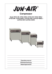
Operators Manual
IT IS THE RESPONSIBILITY OF THE OPERATOR TO MAINTAIN CUSTOMER SAFETY
AT ALL TIMES, AND IT IS IMPERATIVE THAT THE DETAILS SET OUT IN THIS
MANUAL ARE FOLLOWED PRECISELY.
Part No. 90500092
© 1996 NAMCO LIMITED all rights reserved.
No part of this publication may be reproduced by any mechanical, photographic or electronic
process, or in the form of phonographic recording, nor may it be stored in a retrieval system,
transmitted or otherwise copied for public or private use, without permission from
NAMCO EUROPE LIMITED.
While the information contained in this manual is given in good faith and was accurate at
the time of printing, NAMCO EUROPE LIMITED reserve the right to make changes and
alterations without notice.
This machine has been manufactured in accordance with European Community Directives, and
has been tested and complies with the EMC Directive 89/336/EEC by the application of EN55014
and EN55104 standards (see opposite), and as such bears the
marking. Any changes or
modifications to this machine must be in accordance with European Community Directives. Any
unauthorised changes to this product, may contravene such Directives.
Under some conditions of extreme external interference, e.g. radio transmissions, electrostatic
discharge or mains borne transients, some degradation of performance may occur. However the
machine will recover normal performance once the source of interference has ceased or been
removed.
Note:If the game processor resets due to an interuption or reduction of the mains voltage any credits
established may be lost.
This game is not a machine as defined by the Machinery Directive 89/392/EEC
Published by:
NAMCO EUROPE LIMITED
Namco House,
Acton Park Estate,
The Vale,
London W3 7QE
Phone:- 0208-324-6000
Fax:0208-324-6010
SAFETY WARNING
In order to use this machine safely, be sure to read this Operators Manual carefully before
installation, adjustment or use of this machine.
Whenever the owner of this machine entrusts dis-assembly, installation, adjustment or routine
maintenance to another person, the owner should ensure that that person read the appropriate
precautions and relevant sections of this manual before starting work.
In order that no accidents occur when the machine is in operation, strictly follow the notes
on safety as described below.
This manual along with the Installation Manual (where applicable) form an integral part of the
equipment and must be available to the operating and service personnel at all times.
This machine is for indoor use only and should be used only for the purpose intended.
Namco Ltd. bears no responsibility for accidents, injury or damage resulting from unauthorized
changes to, or improper use of this machine.
SAFETY NOTES
The following safety notes are used throughout this manual. Familiarize yourself with
each of these notes and its meaning before installing, servicing or making adjustment
to this machine.
WARNING
Warning denotes a hazard that could result in injury or death.
Do not proceed beyond a warning note until the indicated
conditions are fully understood and met.
CAUTION
Caution denotes a hazard that could result in damage to the machine.
Do not proceed beyond a warning note until the indicated conditions
are fully understood and met.
General Safety Considerations
WARNING
CAUTION
•
Only operate this machine after checking that has been
installed correctly and in accordance with the manual.
•
Parts of this machine move during game play, so there are
places where the distance between the stationary section and
moveable section changes. There are warning notices to keep
hands and feet clear of moving parts, however if the operator
feels that a person is in any danger, he should warn that
person accordingly.
•
The warning notices must always be kept in good condition
and replaced if worn, so that the customer can read them
clearly.
•
If there is an error or problem with the machine, operation
must be stopped immediately and the problem rectified before
any further use.
•
Installation, service, adjustment or routine maintenance
should be carried out by suitably qualified persons only.
•
For continued protection against fire hazard, replace the
mains-in fuses only with the same type and rating. The use of
other fuses or material is prohibited.
•
The power supply inside the monitor will remain hot and have
areas of high voltage even though the machine has been
turned OFF, and there is the possibility of burns or electric
shock. Be careful not to touch these areas.
•
To prevent possible electric shock due to failure, this machine
MUST be fitted with a securely connected EARTHED plug.
•
If at any time the mains supply lead becomes damaged it must
be replaced immediately.
•
Do not turn the power switch ON until the machine has been
installed correctly.
•
Before connecting the machine to the mains supply, ensure that the
machine is set for the correct voltage and that the correct fuses are
fitted.
1. SPECIFICATIONS
POWER SUPPLY:-
230volts AC
AMBIENT OPERATING
TEMPERATURE:-
+5°C to +35°C
MONITOR:-
Pioneer 50” Projector Monitor
(SD-V5070NE/MYVZ)
COIN ACCEPTOR:-
Mars CashFlow - 1 Channel
DIMENSIONS:Assembled
Front Assembly
Ride Assembly
Header Assembly
Coin Tower
1265(w)
1150(w)
1150(w)
1150(w)
219(w)
x
x
x
x
x
2850(d)
720(d)
2130(d)
560(d)
245(d)
x
x
x
x
x
2270(h)
2070(h)
1320(h)
200(h)
715(h)
WEIGHT:Assembled
Front Assembly
Ride Assembly
Header Assembly
Coin Tower
ACCESSORIES:-
Keys:
534kg
235kg
250kg
25kg
24kg
(Cash Door) .......................................... 2
(Coin Door) ........................................... 2
(Back Door) .......................................... 2
IEC Mains Lead .................................................... 1
Operators Manual ................................................. 1
Monitor Manual ..................................................... 1
CashFlow Documents .......................................... 1
Potentiometer ....................................................... 1
Cashbox Base Plate ............................................ 1
Cash Tower Vac-Form Assy ................................ 1
M10x25 Security Button Head S/Steel .............. 9
M10 Spring Washer S/Steel ............................... 9
M10 Flat Washer S/Steel .................................... 9
M8x60 Hex Head Set Screw S/Steel ................. 4
M8 Spring Washer S/Steel ................................. 4
M8 Flat Washer S/Steel ...................................... 4
M6X30 Hex Head Set Screw - BZP ................... 3
M6 Spring Washer - BZP .................................... 3
M6 Flat Washer - BZP ......................................... 3
M4X12 Pz Pan Head - BZP ................................ 4
M4 Spring Washer - BZP .................................... 4
M4 Flat Washer - BZP ......................................... 4
M10 Security Wrench .......................................... 1
M5 Security Wrench ............................................. 1
Page PB
2. HOW TO PLAY
This is a racing game for one player. The player can select from two courses, of
different difficulty level, and to race for position against the computer.
• The objective of the game is to cover the selected course as fast as possible
within the specified time.
• If the finish line is reached within the specified time, the player’s position, time
and jump distance (*) is displayed and the game is over.
* There are three continuous jumping platforms during the course where the
player competes for jumping distance. The distances jumped are displayed
at game over if the player has reached the finish line within the game time.
• The game is over if the specified time period reaches 000
(1)
Operation
•
Steering control is performed by tilting the ride assy to the left or right. Tilt the
ride assy to the left to turn left and tilt it right to turn right.
•
The speed is controlled by operating the accelerator lever on the handle of the
control arm assembly. Pull the lever to increase speed and release the lever to
slow down.
If the control arm is raised, the viewpoint moves up, and the viewpoint moves
down when the arm is lowered.
•
By moving the control arm up and down rhythmically, it is possible to perform
mini jumps at places other than the jump ramps. (expert course only)
•
If the handle arm is held when splashing down onto the water from a jump, it is
possible to go under the water for a short time. (expert course only)
(2)
Starting the Game
•
After inserting the correct amount of money and pressing the start button, the
Select Course screen will be displayed. Tilt the ride assy left or right to choose
the required course and then operate the accelerator lever to select the course
chosen.
•
The game starts when the “GO” sign is displayed on the screen.
•
The game is over if the game time reaches 000
•
If the finish line is reached within the game time, the race results are displayed
and the game is over.
•
A player can enter their name if they reach the finish line in a fast time.
Page 9
3. MAJOR COMPONENTS
Page PB
4.
Moving the Machine
WARNING
NOTE:
•
When moving or carrying the game, make sure to
dis-assemble the game into four parts: header
assembly, Front assembly, ride assembly and coin
tower.
•
The game is fitted with castors to make it easier to
move. Take care when moving the machine on an
inclined surface.
•
The game is still heavy even when separated in to
four parts, ensure that there is an adequate
number of people to move the game.
•
The Header Assembly has a forward centre of
gravity, so it is important that at least two people
are used to fit or remove the Header Assembly.
•
The fitting position of the Header Assembly is very
high, and it is important that a means of reaching
the height safely, without stretching, is available.
(e.g. steps, step stools etc.)
•
The overall height of the main assembly is
2300mm, take care of any overhead obstructions
e.g. light fixtures.
The Front assembly can be further dismantled by removing the
projector from the projector base. (See section 5-1 “Removing
the Projector from the Projector Base”.)
Page 11
5. INSTALLATION
Notes on Installation
WARNING
NEVER turn the power to the machine ON until installation
has been completed.
WARNING
in order to prevent possible electric shocks, be sure that the
machine is connected to the mains supply with a securely
connected earthed plug.
WARNING
So that customers are not injured by the movement of the
Aqua-Jet, ensure that there is at least 500mm separation
between other machines or walls.
CAUTION
In order to avoid damage to the machine due to mis-operation,
ensure that the voltage of the mains supply is
230volts AC.
NOTE
If the location site of this machine has a polished floor it is
recommended that rubber pads are fitted under the level
adjusters to prevent the machine sliding on the floor.
NOTE
In order to gain access to the Power Supply and CPU assemblies,
make sure that the rear of the main cabinet is separated from a
wall or other machine by at least 500mm.
Page PB
WARNING
This machine is designed for indoor use only.
Do not install the machine in the following places.
Page 13
5-1 Removing the Projector from the Projector Base.
WARNING
•
Make sure that the power is turned OFF before
commencing any work.
WARNING
•
The projector Assy weighs approx. 100kg. At least
four people should be used to remove it from it’s
base.
CAUTION
•
The projector assy. is a precision assembly and should be
handled with extreme care, avoiding heavy knocks.
1.
Remove the six security screws (M5x30) and remove the front door.
2.
Disconnect the two projector connectors.
3.
Remove the four hexagonal bolts (M10x130)
Page PB
4.
Remove the two security screws (M5x30) and remove the small cover.
5.
Remove the two pozi head screws (M5x30), unlock and remove the back
door only enough to be able to disconnect the fan connector.
6.
Disconnect the fan connector and remove the back door fully.
7.
Remove the four hexagonal bolts M10x130.
WARNING
After the four hexagonal bolts have been removed, the
projector is only resting on the base. Take care that the
projector is not accidentally knocked or moved to prevent
the projector falling and causing injury.
8.
Lift the projector unit up by approx 10cm from the base then carry it
backward or forward and gently lower it to the ground.
9.
When replacing the projector unit on top of the base, ensure that the
guides on the top of the base fit inside the projector unit base.
WARNING
Take care not to trap fingers or clothing when replacing
the projector unit back on to the base.
Page 15
5-2 Fitting the Header Assembly
WARNING
• The Header Assembly has a forward centre of gravity, so it
is important that at least two people are used to fit or
remove the Header Assembly.
WARNING
• The fitting position of the Header Assembly is very high,
and it is important that a means of reaching the height
safely, without stretching, is available. (e.g. steps, step
stools etc.)
1.
Place the Header Assembly on top of the monitor.
2.
Lift the right end of the Header Assembly (as viewed from the front), and
connect the connector to the top of the monitor. (Ensure that a second
person prevents the Header Assembly from falling.)
3.
Slide the Header Assembly towards the back of the monitor until it is fully
engaged in the locating bracket, taking care not to trap any wires.
4.
Fasten the Header Assembly with the 3off M6x30 Hex head screws, flat
and spring washers.
Page PB
5-3 Connecting the Ride Assy to the Front Assy.
1.
Push the Ride Assembly close to the Front Assy.
2.
Connect the three connectors and the air tube.
3.
Push the Ride Assy fully up to the Front assy, taking care not to trap any
wires.
3.
Fit the Joint Brackets, finger tight, to the Front Assy using 4off Hex Head
Set Screws (M8x60), Spring and Flat Washers for each bracket. When all
screws have been located, tighten all the screws fully.
Page 17
5-4 Assembling the Coin Tower
1.
Connect the connector and place the coin tower on to the base assembly.
2.
Attach the coin tower to the base, taking care not to trap any wires, using
the nine security button head screws (M10x25), flat and spring washers.
NOTE:- Ensure that the two security screws are fitted to the inside of the
cash box area.
3.
Fit the cashbox plate to the inside of the coin tower using four pozi head
screws (M4x12), spring and flat washers.
4.
Place the instruction panel into the panel
support bracket and fasten to the coin
cap using the two security screws
(M5x20).
NOTE:When the machine is fully assembled and in
its final position, lower the 12 level adjusters, (4 on the Monitor Cabinet, 6 on
the Ride Assy and 2 on the coin tower), with a spanner so that the machine is
level and all castors are raised from the floor by approx. 5mm. Tighten the lock
nuts with a spanner to ensure that the level adjusters do not move.
Page PB
5-5 Adjusting the Projector
Due to vibration during moving and assembly of the machine, the projector
convergence may require adjustment. If this is necessary, adjust the projector
using the following procedure.
For details on how to adjust the projector, refer to the “Projector Adjustment
Manual”.
NOTE:
•
If the correct adjustment procedure is not followed, or the wrong buttons
are pressed, it may be impossible to return the projector to its normal
condition.
•
The details for adjusting the projector may differ depending upon which
projector is used, be sure to follow the adjustment procedure according to
the “Projector Adjustment Manual” that is supplied with the game.
1.
Remove the six security screws (M5x30) and remove the front door.
2.
Adjust the projector according to the “Projector Adjustment Manual”.
3.
When adjustment is complete, refit the front door.
Page 19
6. ADJUSTMENTS
WARNING
Adjustments or maintenance on this machine should be
done by qualified personnel only.
6-1 Turning on the Power
After the machine has been installed, turn ON the power. The Power switch is
located on the rear of the Main cabinet. (See section 3 “Major Components”
(page 3).)
6-2 Adjustment Switches
The adjustment switches are located inside the coin door.
1.
Service Switch
Press this switch to obtain game credits without incrementing the play meters.
2.
Test Switch
Slide this switch “ON” to enter test mode.
Test mode allows game testing and the changing of game settings. (Refer to
section 6-3 “Test Mode” (page 14).)
COIN COUNTER
COIN COUNTER
LEFT PLAYER
RIGHT PLAYER
OFF
TEST
ON
SERVICE
Page PB
TEST
SERVICE
6-3 Test Mode
1.
Open the coin door and slide the test switch “ON”. The “Menu Screen” will be
displayed on the monitor.
2.
Select the test required by moving the control handle up or down. The colour
of the selected test will change to red and blink.
3.
Enter the selected test by pressing the start button. Select “EXIT” to return to
the “Menu Screen”
4.
After testing is completed, ensure that the test switch is returned to the “OFF”
position to return to game mode.
The Test Switch must always be in the “OFF” position for normal game mode.
MENU
COIN OPTIONS
-------------------------- (1) Sets the price of play.
(See 6-3-1)
GAME OPTIONS
-------------------------- (2) Sets the game options.
(See 6-3-2)
I/O TEST
-------------------------- (3) Used for testing the switches, control
potentiometers and air spring.
(See 6-3-3)
MONITOR TEST
-------------------------- (4) Used for adjusting the monitor.
(See 6-3-4)
SOUND TEST
-------------------------- (5) Used for adjusting the speaker volume.
(See 6-3-5)
ADS DATA
-------------------------- (6) Displays the accumulated game data.
OTHERS
-------------------------- (7) Used for testing the PC boards and for
initializing all of the settings.
CONTROL ARM:CHOOSE
START:ENTER
(NOTE):•
If the control arm has not been initialized correctly, it may not be possible
to select items correctly. If this happens, refer to section 7, “Initialization”,
and initialize the position of the control arm.
Page 21
6-3-1
Coin Options
a.
Select item (1) “COIN OPTIONS” on the menu screen, to set the
game cost and related settings.
b.
Move the Control Arm up or down to select the required item then
press the start button.
c.
Press the start button to change the settings.
d.
Select “EXIT” and press the start button to return to the menu
screen.
Note:- The price of play on this machine is set within the Cashflow Coin Mech. Ensure
that the Coin Options on the screen are set as shown in the following table.
COIN OPTION
[DEFAULT IN GREEN]
GAME COST
1 COIN 1 CREDIT
............................. (a)
FREE PLAY
OFF ..................... (b)
EXIT
CONTROL ARM:CHOOSE
ITEM
START:CHANGE
CONTENTS
(a) Game Cost
Coins required for one credit - - - - - settable 1 - 9
(b) Free Play
No coins required for game - - - - - - On / Off
Page PB
FACTORY SET
1
OFF
6-3-2
Game Options
a.
Select item (2) “GAME OPTIONS” on the menu screen to set the
game options.
b.
Move the Control Arm up or down to select the required item.
c.
Press the Start button to change the settings. The settings will
change each time the start button is pressed.
d.
Select “EXIT” and press the start button to return to the menu
screen.
GAME OPTIONS [DEFAULT IN GREEN]
GAME TIME
STD
EXP
C ..................... (a)
C
SOUND IN ATTRACT
ON ..................... (b)
AUTO HI SCORE INITIALIZE STD ..................... (c)
HIGH SCORE INITIALIZE
..................... (See section 6-3-2-1)
EXIT
CONTOL:CHOOSE
START:CHANGE
ITEM
DESCRIPTION
A:
No time limit.
B:
Long.
C:
Standard.
D:
Short.
(a) Difficulty
FACTORY SET
B
ON:
Attract sound ON.
BGM
Only background music.
(b) Attract Sound
ON
EFFECT:
Only sound effects.
OFF:
No sound.
STD:
Performed for standard course only.
EXP:
Performed for expert course only.
ON:
Performed for both courses.
OFF:
Not performed.
(c) High score initialize
STD
Page 23
6-3-2-1 High Score Initialization
a.
Select “HIGH SCORE INITIALIZE” on the GAME OPTIONS screen
and press the start button. The screen will change to the HIGH
SCORE INITIALIZE screen.
b.
Move the Control Arm up or down to select the required item.
c.
The high score is initialized (reset) by pressing the start button, and
the screen returns to the GAME OPTIONS screen.
d.
If “NO is selected and the start button pressed, nothing is reset and
the screen returns to the GAME OPTIONS screen.
HI SCORE INITIALIZE
NO
............................ Initialization not performed.
YES
(STD)
............................ Only the standard course hi score is reset.
YES
(EXP)
............................ Only the expert course hi score is reset.
YES
(BOTH)
............................ The hi score for both courses are reset.
CONTROL:CHOOSE
START;ENTER
Page PB
6-3-3
I/O Test
a.
Select item (3) “I/O TEST” on the menu screen.
b.
Move the Control Arm up or down to select the required item.
c.
Press the start button to enter the selected test.
d.
Select “EXIT” and press the start button to return to the menu screen
I/O TEST
DIP
12345678
.................................... (a)
SWITCH TEST
.................................... (b)
AIR SPRING TEST
.................................... (c)
EXIT
CONTROL:CHOOSE
START:ENTER
(a) Displays the state of the PCB Dip switches, when a switch is ON the
number is shown in red.
(b) Tests the switches and control potentiometers. (See 6-3-3-1.)
(c)
Tests the air spring. (See 6-3-3-2.)
Page 25
6-3-3-1
Switch Test
a.
Select “SWITCH TEST” on the menu screen and press the start
button. The following screen is displayed.
b.
Operate the accelerator lever and start button together to return to
menu screen
I/O TEST
TEST SW
COIN SW
SERVICE SW
START BUTTON
ON
OFF
OFF
OFF
...............
...............
...............
...............
(a)
(b)
(c)
(d)
ACCEL LEVER
0000
0000
FREE ............... (e)
SWING
0000
0000
CENTRE ........... (f)
HANDLE POLE
0000
0000
............... (g)
START+LEVER:EXIT
(a)
Test Switch:
“ON” during test mode.
(b)
Coin Switch:
‘OFF’ will change to ‘ON’ when the coins to the
correct game value have been inserted through
the Cashflow acceptor or the coin switch is
operated (S18 mech).
(c)
Service Switch
‘OFF’ will change to ‘ON’ each time the service
switch is pressed.
(d)
Start button
‘OFF’ will change to ‘ON’ each time the start
button is pressed. The button lamp will light
each time the button is pressed.
(e)
Accelerator Lever
‘FREE’ will change to ‘OK’ each time the lever
is operated fully.
(f)
Ship Swing
‘CENTER’ is displayed when in the central
stand by position.
‘RIGHT’ and ‘OK’ is displayed when swung fully
to the right.
‘LEFT’ and ‘OK’ is displayed when swung fully
to the left.
(g)
Handle Pole
‘UP OK’ is displayed when the control arm is
fully raised, ‘‘DOWN OK’ is displayed when the
control arm is fully lowered.
NOTE: If ‘OK’ does not appear when the ride is swung to its extreme
travel, re-initialize the game as described in section 7
Page PB
6-3-3-2
Air Spring Test
WARNING
The ride moves during the Air Spring test. Ensure that
hands and feet are clear before starting the test.
a.
Select ‘AIR SPRING’ test on the I/O TEST screen and press the start
button. The following screen is displayed.
b.
Move the Control Arm up or down to select the required item.
c.
Press the start button to enter the selected test.
d.
Select “EXIT” and press the start button to return to the menu screen
AIR SPRING TEST
NOW AIR SPRING OFF (DOWN) ...................... (a)
GO STATE ON
(UP)
...................... (b)
EXIT
CONTROL:CHOOSE
START:SELECT
(a)
Displays the current position of the air spring.
(b)
Indicates the direction the air spring will move. Select ‘GO STATE’ and
press the start button.
If the spring is UP it will go DOWN, and if the spring is DOWN it will go UP.
Page 27
6-3-4
Monitor Test
a.
Select “MONITOR TEST” on the menu screen and press the start
button. The following screen is displayed.
b.
Select an item by moving the control arm up or down. When the start
button is pressed the screen will change to the selected pattern.
c.
To return to MONITOR TEST screen from a test pattern, press the
start button.
d.
Select “EXIT” and press the start button to return to the menu screen
MONITOR TEST
GRADATION PATTERN
CROSSHATCH PATTERN [CRT]
CROSSHATCH PATTERN [PROJECTOR]
WHITE WINDOW [H]
WHITE WINDOW [M]
WHITE WINDOW [L]
INTERLACE PATTERN
VIEW ANGLE ADJUST [CRT]
VIEW ANGLE ADJUST [PROJECTOR]
FULL WHITE
EXIT
CONTROL:CHOOSE
Page PB
START:ENTER
6-3-5
Sound Test
a.
Select “SOUND TEST ” on the menu screen and press the start
button. The following screen is displayed.
b.
Move the Control Arm up or down to select the required item.
c.
Press the start button to enter the selected test.
d.
Move the control arm up or down to alter the setting of the
selected item.
d.
Select “EXIT” and press the start button to return to the menu
screen
SOUND TEST
`[DEFAULT IN GREEN]
GAME VOLUME
FRONT SP
TANK
SP
ATTRACT VOLUME
REQUEST SONG NO.
2C
2C
.................... (a)
............... (b)
2C
.................... (c)
001
.................... (d)
MESSAGE
......... The selected song
description is displayed
EXIT
CONTROL:CHOOSE
START:ENTER
(a) Front speaker volume
Adjusts the volume of speakers in the header.
(b) Tank speaker volume
Adjusts the volume of the tank speaker on the
ride.
(c)
Adjusts the volume during attract mode.
Attraction volume
(d) Sound selection
Each digit of the REQUEST SONG No. can be
changed by moving the control arm up or
down. Each number will produce a different
tune or sound when the start button is pressed.
001 will produce a stereo test. First a tone will
be produced from the front speakers, then from
the tank speaker and then from all speakers.
Page 29
6-3-6
ADS Data
Select “ADS DATA ” on the menu screen and press the start button.
The book keeping data for the game will be displayed.
6-3-7
Others
Select “OTHERS” on the menu screen and press the start button.
This screen is used to test the PCB and to reset the game to factory
settings.
Page PB
7 INITIALIZATION
Adjustments When Replacing Parts (Initialization)
The following adjustments should always be performed after replacing the
game PC board, ROM, or Control Pots.
The game will not operate correctly if these adjustments are not made.
a)
Ensure that Control Handle assembly and Ride assembly are in the
neutral stand-by position.
b)
Slide the test switch “ON” while pressing the service switch. The following
screen will be displayed on the monitor.
VOLUME INITIALIZE
ON
OFF
OFF
OFF
TEST SW
COIN SW
SERVICE SW
START BUTTON
0000 0000
0000 0000
0000 0000
ACCEL LEVER
SWING
HANDLE POLE
CENTRE
UP
START:HANDLE POLE ADJUST
c)
At this time the Ride assembly and Accelerator lever are initialized.
d)
Press the start button to initialize the Control Arm. The following screen
will be displayed.
HANDLE POLE ADJUST
HANDLE POLE
UP
DOWN
0000 0000
PLEASE MAKE HANDLE POLE
UPDOWN TO ADJUST!
e)
Move the Control Arm UP and DOWN through its full range of movement.
This motion will be registered as the motion range of the Control Arm.
f)
Slide the test switch “OFF” to return to normal game mode.
Page 31
8. REMOVING AND REPLACING ASSEMBLIES AND PARTS.
WARNING
•
Adjustments or maintenance on this machine should be carried out by
qualified personnel only.
•
Do not make any alterations to this machine without prior approval. Doing
so could cause unforeseeable danger.
•
Only parts specified by Namco Europe Ltd. should be used when replacing
or repairing parts (including screws).
•
Ensure that power to the machine is turned OFF before commencing any
maintenance work (troubleshooting, repairs etc.)
•
If performing work not described in this manual, be sure to contact your
distributor for instructions as no responsibility will be accepted for
damage or injury.
•
Parts of the power supply, projector monitor and air compressor remain
hot or carry high voltage even after switching OFF and could cause burns
or electric shock. Take care not to touch these parts accidentally.
•
Make sure that the machine is switched OFF before connecting or
disconnecting any plugs or connectors.
•
When removing the mains connector from the machine, or the mains plug
from the wall outlet, always grasp the plug not the cable.
8-1
COMPRESSOR ASSEMBLY
NOTE:
There are no user serviceable parts on the compressor assembly.
Under no circumstances should any regulator valves be adjusted.
Altering the regulator valves could lead to serious damage to the system
or injury to personnel
WARNING
•
Parts of the compressor become very hot during use. Take care not to
touch the compressor when it is hot.
Page PB
8-2 Ride Assembly
8-2-1
Replacing the Swing Potentiometer
WARNING
•
•
Make sure that the power is turned OFF before
commencing any work.
Do not let any one get on the ride assembly while
replacing the potentiometer to prevent injury by
trapped hands or fingers.
1)
Remove the two pozi head screws (with flat and spring
washers)(M5x10) and remove the potentiometer cover.
2)
Remove the two pozi head screws (with flat and spring
washers)(M5x10) and remove the maintenance cover.
3)
Disconnect the connector. Loosen the grub screw (M4x12) and
remove the potentiometer complete with its mounting bracket.
Page 33
4)
Remove the potentiometer from the mounting bracket and replace
with a new potentiometer.
5)
Re-assemble in reverse order.
NOTE: When refitting the potentiometer and bracket ensure that the grub
screw engages on the flat of the potentiometer shaft, and the
notch in the mounting bracket engages on the pin.
6)
8-2-2
Re-initialize the game. (Refer to section 7 ‘Initialization’)
Removing the Tank
WARNING
•
Make sure that the power is turned OFF before
commencing any work.
1)
Remove the four security screws (M5x12) and four security screws
(M5x20), and remove the tank.
2)
Re-assemble in reverse order.
Page PB
8-2-3
Replacing Solenoid Valve A
WARNING
•
Make sure that the power is turned OFF before
commencing any work.
1)
Remove the tank. (Refer to section 8-2-2 ‘Removing the Tank’
2)
Disconnect the connector.
3)
Push the blue release of the elbow union in, and while holding it in,
pull out the air tube. (There will be a loud noise as the air pressure is
released.)
4)
Remove the two pozi head screws (M4x35) and remove the solenoid
valve A.
5)
Remove the elbow union, half union and silencer from the removed
solenoid valve, and install them on to the new solenoid valve.
6)
Re-assemble in reverse order. (The air tube is just a push fit.)
NOTE:
•
Take care that no dirt or other matter gets in to the air tube while
it is disconnected.
•
After refitting the air tube, give it a gentle pull to ensure that it is
connected properly and will not come loose.
Page 35
8-2-4
Replacing Solenoid Valve B
WARNING
•
Make sure that the power is turned OFF before
commencing any work.
1)
Remove the tank. (Refer to section 8-2-2 ‘Removing the Tank’
2)
Disconnect the connector.
3)
Push the blue release of the elbow union in, and while holding it in,
pull out the air tube. (There will be a loud noise as the air pressure is
released.)
4)
Remove the two pozi head screws (M4x35) and remove the solenoid
valve B.
5)
Remove the half union, taper-screw plug and silencer from the
removed solenoid valve, and install them on to the new solenoid
valve.
6)
Re-assemble in reverse order. (The air tube is just a push fit.)
NOTE:
•
Take care that no dirt or other matter gets in to the air tube while
it is disconnected.
•
After refitting the air tube, give it a gentle pull to ensure that it is
connected properly and will not come loose.
Page PB
8-3 Control Arm Assembly
8-3-1
Replacing the Accelerator Potentiometer
WARNING
•
Make sure that the power is turned OFF before
commencing any work.
1)
Remove the four security screws (M5x12) and remove the accelerator
cover.
3)
Disconnect the connector. Loosen the grub screw (M3x5) and remove
the potentiometer complete with its mounting bracket.
4)
Remove the potentiometer from the mounting bracket and replace
with a new potentiometer.
5)
Re-assemble in reverse order.
NOTE: When refitting the potentiometer and bracket ensure that the grub
screw engages on the flat of the potentiometer shaft, and the
wire harness is secured with the two cord grips so that it does not
get caught or pinched by the moveable section.
6)
Re-initialize the game. (Refer to section 7 ‘Initialization’)
Page 37
8-3-2
Replacing the Control Arm Potentiometer
WARNING
•
Make sure that the power is turned OFF before
commencing any work.
1)
Remove the tank. (Refer to section 8-2-2 ‘Removing the Tank’).
3)
Disconnect the connector. Loosen the grub screw (M4x5) and remove
the potentiometer complete with its mounting bracket.
4)
Remove the potentiometer from the mounting bracket and replace
with a new potentiometer.
5)
Re-assemble in reverse order.
NOTE: When refitting the potentiometer and bracket ensure that the grub
screw engages on the flat of the potentiometer shaft, and the lug
on the mounting bracket engages in the slot of the main
metalwork.
6)
Re-initialize the game. (Refer to section 7 ‘Initialization’)
Page PB
8-3-3
Replacing the Start Switch or Lamp
WARNING
•
Make sure that the power is turned OFF before
commencing any work.
1)
Remove the eight security screws (M5x12) and lift the top vac-form
sufficiently to remove the switch and lamp from the push button.
2)
Remove the top vac-form.
3)
Replace the lamp or switch.
4)
Re-assemble in reverse order.
Page 39
8-4 Header Assembly
8-4-1
Replacing the Fluorescent Lamp or Starter
WARNING
•
Make sure that the power is turned OFF before
commencing any work.
WARNING
•
The Header Assembly is very high, and it is important
that a means of reaching the height safely, without
stretching, is available. (e.g. steps, step stools etc.)
WARNING
•
The fluorescent lamp may be hot, take care when
handling.
1)
Remove the four security screws (M5x20), and remove the acrylic
sign board.
2)
Replace the fluorescent lamp or starter.
3)
Re-assemble in reverse order.
Page PB
9. PARTS
Header Assy
ITEM
DESCRIPTION
PART No
1
HEADER CABINET
37100110
2
LOUDSPEAKER GRILLE
46000083
4
HEADER ACRYLIC
30000234
5
ACRYLIC RETAINING BRACKET
46000084
E1
FLOURESCENT TUBE 18" 15W
64500009
E3
LOUDSPEAKER 5½" FULL RANGE
62000065
E4
STARTER 240v 4-80W UNIVERSAL
63000000
E5
STARTER HOLDER
64800001
M6x16 HEX HEAD SET SCREW - BZP
26500311
M6 SPRING WASHER - BZP
28000028
M6 FLAT WASHER - BZP
28000166
M4x16 PZ PAN HEAD - BLACK
26300294
B1
M4 SPRING WASHER - BLACK
28000127
M4 FLAT WASHER - BLACK
28000132
B3
M5x20 SECURITY BUTTON HEAD - SUS
26300039
B6
No4x½" PZ PAN HEAD WOODSCREW - BZP
26100070
B7
M4x12 PZ PAN HEAD - BZP
26300057
B8
M4x16 PZ PAN HEAD - BZP
26300383
B9
M4 WHIZZTITE NUT - YEL ZNC
27000128
B2
Page 41
Coin Tower
ITEM
DESCRIPTION
PART No
1
COIN TOWER TOP VAC-FORM
46000057
2
INSTRUCTION DECAL SUPPORT BRACKET
46000146
3
PLAY INSTRUCTION DECAL - ACRYLIC
30000235
5
WOODEN CASHBOX
37100093
6
M12 ADJUSABLE FOOT
88300311
7
3.5-6v METER - PANEL MOUNT
65000002
8
MINIATURE SLIDE SWITCH - DPCO
60000023
9
SERVICE SWITCH 7mm RED - F424
60000059
B1
No8x½" PZ CSK WOODSCREW - BZP
26100265
B2
M3x10 PZ PAN HEAD - BZP
26300067
B7
M5x16 SECURITY BUTTON HEAD - SUS
26300032
B8
M5x20 SECURITY BUTTON HEAD - SUS
26300039
B9
M5x14 RAWLNUT
27000153
Page 42
Cabinet Base
PART No
ITEM
1
INTERLOCK SWITCH
6000006
15
FUSE - 1¼" 1A QB
63500424
2
INTERLOCK SWITCH COVER
39000028
16
COMPRESSOR ASSY - TYPE 600 W/LOW READ GAUGE
46000058
17
FAN 230v 4½"
67000015
18
ROTARY FAN
45000940
19
PLASTIC STARTER CAPACITOR
46000041
ITEM
DESCRIPTION
DESCRIPTION
PART No
3
SCHAFFNER 10A DOUBLE FUSED MAINS IN FILTER
62500011
4
SHAFFNER BOOT 1B3
66000017
5
10A 20mm FUSE
63500705
20
SSR
46000164
6
SWIVEL CASTOR 75mm
59000005
B1
M5x20 PZ PAN HEAD - BZP
26300576
7
M16 ADJUSTABLE FOOT
88300079
M5 SPRING WASHER - BZP
28000145
8
CONDENSATE BOTTLE 0.5ltr
46000079
M5 FLAT WASHER - BZP
28000144
9
WOODEN BLANKING STRIP
37100109
M4x20 PZ PAN HEAD - BZP
26300055
M4 SPRING WASHER - BZP
28000035
M4 FLAT WASHER - BZP
28000036
M8x25 HEX HEAD SET SCREW - BZP
26300050
M8 SPRING WASHER - BZP
28000176
M8 FLAT WASHER - BZP
28000175
M5x30 PZ PAN HEAD - BZP
26300595
10
AQUA JET SUPER SYSTEM 22 PCB ASSY
11
4 CHANNEL AMP PCB - SUPER SYSTEM 22
12
LAMP DRIVER PCB - SINGLE CHANNEL
46000020
13
3 CHANNEL AMPLIFIER - Ver3
46000036
14
ASTEC SA301-3400 SMPSU 5v 30A
83000001
B2
XAJ-PCB
XCYB-AMPCB
B3
B4
Page 43
Cabinet
ITEM
DESCRIPTION
PART No
1
PIONEER REAR PROJECTION MONITOR 230v
84000028
2
CABINET FRONT PANEL
37100106
3
LOUDSPEAKER GRILLE
45000701
4
HARNESS CONNECTOR BRACKET
46000082
5
ADJUSTABLE FOOT MOUNTING BRACKET
45000204
6
SIDE DECAL - LHS/RHS
40000381
7
FAN 4½" 230v
67000015
8
FRONT DECAL
40000383
9
LOUDSPEAKER 6½" - BASS
62000068
M5x30 SECURITY BUTTON HEAD - SUS
26300036
M5x25 PZ PAN HEAD - BZP
26300049
M5 SPRING WASHER - BZP
28000144
M5 FLAT WASHER - BZP
28000145
M10x130 HEX HEAD SET SCREW - BZP
26500475
M10 SPRING WASHER - BZP
28000023
PIONEER CLAMP WASHER
46000163
B1
B2
B3
Page 44
Control Arm
ITEM
DESCRIPTION
PART No
1
CONTROL ARM TOP VAC-FORM
46000054
2
NAMCO DECAL
40000390
3
AQUAJET DECAL
40000389
4
ACCELERATOR DECAL
40000392
5
HANDLEBAR COVER VAC-FORM
46000055
6
CONTROL ARM BOTTOM VAC-FORM
46000053
7
RPB RECTANGULAR PUSH BUTTON - YELLOW "START"
60500044
8
START DECAL
40000391
9
WARNING DECAL
40000393
10
HANDLEBAR GRIP - LHS/RHS
46000141
B1
M5x16 SECURITY BUTTON HEAD - SUS
26300032
Page 45
ITEM
DESCRIPTION
PART No
2
RUBBER STOPPER RI-30
46000007
3
PITCH SPRING BUMPER
46000075
4
PITCH SPRING
46000073
5
PITCH STOPPER RUBBER BLOCK
46000072
6
PITCH POTENTIOMETER MOUNTING BRACKET
46000132
7
PITCH POTENTIOMETER
X008-021
8
BEARING UCP-206-NSK
46000080
9
SPRING SLEEVE
46000131
M16 FULL NUT - BZP
27000205
M16 SPRING WASHER - BZP
28000301
11
BEARING SECURING WASHER 40 OD x 17 ID x 3.2T
46000133
12
BEARING SPACER
46000130
13
PITCH MAIN SHAFT
46000129
M4x12 PZ PAN HEAD - BZP
26300057
M4 SPRING WASHER - BZP
28000035
M4 FLAT WASHER - BZP
28000036
M4x8 HEX SOCKET SET SCREW - BZP
26300083
M14x50 HEX HEAD SET SCREW - BZP
26500502
M14 SPRING WASHER - BZP
28000302
M14 FLAT WASHER - BZP
28000021
M8x20 SOCKET HEAD CSK SCREW - BZP
26300862
10
B1
B3
B4
B5
Page 46
Accelerator
ITEM
DESCRIPTION
PART No
11
HANDLEBAR METALWORK
46000134
12
ACCELERATOR PLATE
46000135
13
ACCELERATOR POTENTIOMETER SHAFT
46000136
14
ACCELERATOR POTENTIOMETER BRACKET
46000137
15
ACCELERATOR SPRING STOP PIN
46000138
16
ACCELERATOR LIMIT STOP TUBE
46000139
17
ACCELERATOR LIMIT STOP BUMPER
46000074
18
ACCELERATOR SPRING
46000157
19
ACCELERATOR SLIDE COVER
46000140
25
ACCELERATOR HANDLE
46000076
27
SPACER - 8mm OD x 3mm LONG
46000142
29
OILITE BUSHING LFF 0705
46000077
30
OILITE BUSHING LFF 1012
46000078
E4
ACCELERATOR POTENTIOMETER
X008-021
B7
M3x5 HEX SOCKET SET SCREW - BZP
26300111
B10
M5 WHIZZTITE NUT - BZP
27000151
M5x8 PZ PAN HEAD - BZP
26300570
M5 SPRING WASHER - BZP
28000144
3/16" x 3/4" FLAT WASHER - BZP
28000224
B15
Page 47
Ride Assy
ITEM
DESCRIPTION
PART No
2
RIDE STAND-ON WOODEN PLATE
37100111
5
LOUDSPEAKER MOUNTING WOOD
37100112
6
LOUDSPEAKER MESH
46000120
24
AIR VALVE VK334-6GS-01 12vDC
46000069
25
CONNECTOR KQL08-01S
46000147
26
CONNECTOR KQH08-01S
46000148
27
CONNECTOR KQU08-10
46000149
28
CONNECTOR KQL10-00
46000150
29
AN103-01
46000126
30
PLUG 1/8
46000167
32
TUBE TU1065B 50mm
46000151
33
TUBE TU0805B 55mm
46000155
38
CONTROL ARM WOOD SUPPORT BRACKET
46000162
E2
LOUDSPEAKER 5½" FULL RANGE
62000065
M4x20 PZ PAN HEAD - BLACK
26300391
M4 SPRING WASHER - BLACK
28000127
M4 FLAT WASHER - BLACK
28000132
M4x40 PZ PAN HEAD - BZP
26300443
M4 SPRING WASHER - BZP
28000035
M5x16 PZ PAN HEAD - BZP
26300580
M5 SPRING WASHER - BZP
28000144
M5 FLAT WASHER - BZP
28000145
M5x35 PZ PAN HEAD - BZP
26300613
M5 SPRING WASHER - BZP
28000144
M5 FLAT WASHER - BZP
28000145
No6x½" PZ FLANGE - BZP
26100074
B1
B2
B3
B5
B9
Page 48
ITEM
DESCRIPTION
PART No
1
RIDE STAND-ON METAL BASE
46000117
3
SIDE VAC-FORM SUPPORT BRACKET - LHS
46000118
4
SIDE VAC-FORM SUPPORT BRACKET - RHS
46000119
8
SIDE VAC-FORM MOUNTING BRACKET
46000122
10
REAR VAC-FORM CLOSING BRACKET
46000124
31
TUBE TU1065-B
46000151
M8x20 HEX HEAD SET SCREW - BZP
88300700
M8 SPRING WASHER - BZP
28000176
M8 FLAT WASHER - BZP
28000175
M5x16 PZ PAN HEAD - BZP
26300580
M5 SPRING WASHER - BZP
28000144
M5 FLAT WASHER - BZP
28000145
M5x25 PZ PAN HEAD - BZP
26300049
M5 SPRING WASHER - BZP
28000144
M5 FLAT WASHER - BZP
28000145
M4x10 PZ PAN HEAD - BZP
26300366
M4 SPRING WASHER - BZP
28000035
M4 FLAT WASHER - BZP
28000036
B1
B3
B4
B10
Page 49
Ride Vac-Forms and Decals
ITEM
DESCRIPTION
PART No
7
FRONT VAC-FORM MOUNTING BRACKET
46000121
11
LOWER VAC-FORM - RHS
46000049
12
LOWER VAC-FORM - LHS
46000048
13
UPPER STANDING AREA VAC-FORM
46000050
14
REAR VAC-FORM
46000051
15
TOP FRONT VAC-FORM
46000052
16
REAR EXHAUST DECAL
40000384
17
SIDE FLASH DECAL - LHS UPPER
40000385
18
SIDE FLASH DECAL - RHS UPPER
40000386
19
SIDE FLASH DECAL - LHS LOWER
40000387
20
SIDE FLASH DECAL - RHS LOWER
40000388
21
3M ANTI SLIP FLOOR MAT - STANDING AREA
46000070
22
FRONT VAC-FORM CLOSING BRACKET
46000125
35
SUPERVISION WARNING DECAL
40000396
M5x16 SECURITY BUTTON HEAD - SUS
26300032
M5 FLAT WASHER- SUS
28000015
B7
M5x25 SECURITY BUTTON HEAD - SUS
26300033
B8
M5x14 RAWLNUT
27000153
B6
Page 50
Page 51
3M ANTI SLIP FLOOR MAT - REAR BASE
BASE WARNING DECAL
CONNECTOR KQL10-U02
M5x16 SECURITY BUTTON HEAD - SUS
3/8"x3/4" HEX HEAD SET SCREW - BZP
33
34
36
B3
B10
46000168
46000169
46000170
46000171
RUBBER SKIRT - RHS
RUBBER SKIRT FIXING PLATE - BASE
RUBBER SKIRT FIXING PLATE - RIDE
26500901
26300032
46000161
40000394
46000071
RUBBER SKIRT - LHS
PARTS NOT SHOWN
AIR SPRING MOUNTING BRACKET - UPPER
46000017
46000092
MAIN FLOOR SIDE COVER - LHS
8
22
PART No
46000093
DESCRIPTION
MAIN FLOOR SIDE COVER - RHS
7
ITEM
Ride Base Assy
Page 52
26500134
RUBBER STOPPER - RI-30
AIR SPRING
LINK BALL - TBS12
SHOCK ABSORBER - FK/2530/S/NM1
SIDE LOAD ADAPTOR - KG/001/NM
M10x25 HEX HEAD SET SCREW - BZP
41
42
44
46
47
B14
B10
B6
46000065
RUBBER STOPPER - RI/65/HD
40
27000201
28000020
28000214
M12 NYLOC NUT - BZP
M12 FLAT WASHER - BZP
28000213
26500902
3/8" x 1 3/16" HEX HEAD SET SCREW - BZP
3/8" FLAT WASHER - HEAVY DUTY - BZP
28000198
M10 FLAT WASHER - BZP
3/8" SPRING WASHER - BZP
28000023
M10 SPRING WASHER - BZP
46000064
46000062
46000060
46000007
46000059
46000106
STEERING ARM MOUNTING BRACKET
46000087
RIDE BASE
PART No
2
DESCRIPTION
21
ITEM
Page 53
26300336
SWIVEL CASTOR 75mm
ADJUSTABLE FOOT M20x70
M4x12 PZ PAN HEAD - BZP
38
39
B6
B5
B4
B1
46000160
HARDENED BLOCK
26
28000198
40000072
40000394
"FORK HERE" DECAL
BASE SIDE WARNING DECAL
ITEMS NOT SHOWN
28000023
M10 FLAT WASHER - BZP
26500134
M10x25 HEX HEAD SET SCREW - BZP
M10 SPRING WASHER - BZP
28000175
M8 FLAT WASHER - BZP
26500407
28000176
28000037
M8x30 HEX HEAD SET SCREW - BZP
M8 SPRING WASHER - BZP
28000028
26500311
M6x16 HEX HEAD SET SCREW - BZP
M6 FLAT WASHER - BZP
28000036
M4 FLAT WASHER - BZP
M6 SPRING WASHER - BZP
28000035
M4 SPRING WASHER - BZP
59000005
46000108
46000094
YAW MECHANICAL STOPPER MNTG BRACKET
9
46000090
46000088
46000086
YAW DRIVE SHAFT
ROSTA SPRING SHAFT MOUNTING ASSY
PART No
5
MAIN FLOOR BASE
3
DESCRIPTION
1
ITEM
Page 54
26500311
ROSTA SPACER WASHER
ROSTA RETAINING BRACKET
ROSTA SPRING REAR PACKING BRACKET
ROD EYE - RBL16BD
ROSTA SPRING DR-S-27x60
BEARING - UCPA/204/FYH
M16x40 SOCKET HEAD CAP SCREW - BZP
M6x16 HEX HEAD SET SCREW - BZP
18
19
32
45
48
49
B8
M12 FULL NUT - BZP
M12 SPRING WASHER - BZP
M12 FLAT WASHER - BZP
B14
B17
B19
28000020
28000019
27000022
26300940
28000037
M12x25 CSK CAP SCREW - BZP
28000028
M6 FLAT WASHER - BZP
46000068
46000067
46000063
46000114
46000104
46000103
46000102
M6 SPRING WASHER - BZP
B13
B9
26500602
ROSTA SPRING RETAINING WASHER
46000098
LINK BALL MOUNTING SHAFT
17
PART No
46000095
13
DESCRIPTION
ROSTA SPRING MOUNTING SHAFT
10
ITEM
Page 55
MAIN FRONT JOINT BOX COVER
BEARING END SPACER
15
26300366
YAW POTENTIOMETER
YAW POT ACCESS PLATE
YAW POTENTIOMETER CLOSING BRACKET
SPHERICAL BEARING - PB 22
TUBE - TUO805B
M4x10 PZ PAN HEAD - BZP
21
27
28
43
51
B15
B9
B7
B6
B3
B2
B1
46000155
YAW POTENTIOMETER MOUNTING BRACKET
20
28000301
28000240
27000205
M16 FLAT WASHER - BZP
28000037
M16 FULL NUT - BZP
M16 SPRING WASHER - BZP
28000028
M6 FLAT WASHER - BZP
26500311
M6 SPRING WASHER - BZP
26300083
M6x16 HEX HEAD SET SCREW - BZP
28000198
M4x8 HEX SOCKET SET SCREW - BZP
28000023
M10 FLAT WASHER - BZP
26500134
M10 SPRING WASHER - BZP
26300032
M10x25 HEX HEAD SET SCREW - BZP
28000145
M5x16 SECURITY BUTTON HEAD - BZP
28000032
26300580
M5x16 PZ PAN HEAD - BZP
M5 FLAT WASHER - BZP
28000036
M4 FLAT WASHER - BZP
M5 SPRING WASHER - BZP
28000035
M4 SPRING WASHER - BZP
46000061
46000110
46000109
X008-021
46000105
RIDE ASSEMBLY JOINT TUBE MOUNTING BRACKET
16
46000101
46000100
46000097
46000091
MAIN FRONT JOINT BOX
6
12
PART No
46000089
DESCRIPTION
DISTRIBUTION BOX
4
ITEM
Page 56
10.SCHEMATICS
Page 57
Page 58
Page 59
Page 60