1
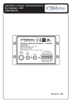
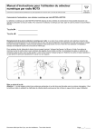
NMEA2000 to Modbus Gateway Part No. 3155 User Manual Revision 1.21 Offshore Systems UK Ltd Unit 11 Milton Business Centre Wick Drive, New Milton, BH25 6RH, UK www.osukl.com Page 2 of 55 Contents 1 2 3 Introduction ................................................................................................ 6 1.1 Firmware Revision ............................................................................... 6 1.2 Product Features ................................................................................. 6 Installation................................................................................................... 6 2.1 Unpacking the box............................................................................... 6 2.2 Choosing the mounting location ......................................................... 6 2.3 Mounting the unit ............................................................................... 7 2.4 Connecting the RS485 Modbus Interface ........................................... 7 2.5 Connecting the NMEA2000 Interface ................................................. 8 Configuration............................................................................................... 8 3.1 Modbus Communication Parameters ................................................. 8 3.2 Modbus Slave Address ........................................................................ 9 3.3 Modbus Termination Resistor........................................................... 10 3.4 NMEA Device Instance ...................................................................... 10 4 Front Panel Indicators and Switches ......................................................... 10 5 Fault Finding / Troubleshooting ................................................................ 10 5.1 Communications error Led................................................................ 11 5.2 Invalid Modbus Message Error Led ................................................... 11 5.3 Unmarked LED – PGN became Data Not Available ........................... 11 6 Data Naming Convention .......................................................................... 11 7 Modbus Data Registers ............................................................................. 11 Page 3 of 55 7.1 Engine Instance 0 Registers .............................................................. 13 7.2 Engine Instance 1 Registers .............................................................. 15 7.3 Engine Instance 2 Registers .............................................................. 17 7.4 Fuel Tank Registers ........................................................................... 19 7.5 Fresh Water Tank Registers .............................................................. 21 7.6 Grey Waste Water Tank Registers .................................................... 23 7.7 Oil Tank Registers.............................................................................. 25 7.8 Black Water Tank Registers .............................................................. 27 7.9 AC Instance 0 Registers ..................................................................... 29 7.10 AC Instance 1 Registers ..................................................................... 29 7.11 AC Instance 2 Registers ..................................................................... 30 7.12 AC Instance 3 Registers ..................................................................... 30 7.13 AC Instance 4 Registers ..................................................................... 31 7.14 AC Instance 5 Registers ..................................................................... 31 7.15 Battery Bank Registers ...................................................................... 32 7.16 Battery Charger Instance 0 Registers................................................ 34 7.17 Battery Charger Instance 1 Registers................................................ 36 7.18 Battery Charger Instance 2 Registers................................................ 38 7.19 Battery Charger Instance 3 Registers................................................ 41 7.20 Switch Bank Status and Control Registers ........................................ 43 7.21 Switch Bank Holding Registers .......................................................... 43 8 Maintenance ............................................................................................. 51 9 Technical Specification ............................................................................. 51 Page 4 of 55 10 Technical Support.................................................................................. 52 11 Warranty ............................................................................................... 53 Page 5 of 55 1 Introduction The Offshore System’s NMEA2000 to Modbus Gateway (Part No 3155) makes NMEA2000 messages from Engine, Generators, Tanks, Batteries, AC Sources and Switch Banks available over a Modbus interface to PLC based vessel monitoring systems. This unit is designed to operate in a protected marine environment such as an engine room or below decks. It is very important that it is installed and set up correctly according to this manual. Please read and follow the installation and setup instructions carefully to achieve the best results. 1.1 Firmware Revision The information in this manual corresponds to firmware revision 1.05 1.2 Product Features The 3155 NMEA2000 to Modbus Gateway has the following features: RS485 Modbus Interface RTU protocol NMEA2000 Interface DIN Rail mount enclosure Passes NMEA2000 messages from Engines, Generators, Batteries, AC Sources, Fuel Tanks, Fresh Water Tanks, Grey Water Tanks, Black Water Tanks and Oil Tanks to the Modbus Interface Has easy communications setup controls for the RS485 Interface Status and Warning lights for all data transfers Allows monitoring and Control of 8 switch banks of 28 switches (224 in total) 2 Installation 2.1 Unpacking the box You should find the following items in the 3155 shipping box: 1 x 3155 NMEA2000 to Modbus Gateway 1 x 3155 User Manual (This document) 2.2 Choosing the mounting location The unit is designed to be mounted on a DIN rail in an electrical cabinet with free air circulation in a dry location below decks. The cabinet may be located in an engine room providing the ambient temperature does not exceed 50⁰C (125⁰F). The location needs to allow for connection to the NMEA2000 interface cable and the RS485 Modbus cable. Page 6 of 55 2.3 Mounting the unit The unit should be hooked over the top of the DIN rail and then pushed back into location until the red tab at the bottom of the rear of the unit snaps behind the lower edge of the DIN rail. Figure 1 DIN Mounting The unit can be dismounted from the DIN rail by using a screwdriver to release the red tab whilst lifting the unit upwards from the mounting rail. Figure 2 DIN Dismounting 2.4 Connecting the RS485 Modbus Interface The RS485 Modbus cable should be connected to the terminal block on the lower edge of the 3155 unit. Tighten the terminal block screws to grip the cable securely ensuring that a sound electrical connection has been made. Page 7 of 55 Figure 3 RS485 Connections The RS485 Modbus Interface wires are connected as follows: Description Transceiver Terminal 1, V1 Voltage Transceiver Terminal 0, V0 Voltage Signal Ground EIA/TIA-485 B/B’ A/A’ C/C’ Name Data + Data Common Modbus Name D0 D1 Common 2.5 Connecting the NMEA2000 Interface The NMEA2000 interface cable on the unit should be connected to a nearby NMEA2000 Tee connector (part number 3802). The male end of the cable should be inserted into the female Tee connection noting the position of the keyway in the plug and the socket. The unit can be connected with power on or off without any damage. Ensure that the locking ring is securely tightened so that the connection remains sound. 3 Configuration 3.1 Modbus Communication Parameters The 3155 NMEA2000 to Modbus Gateway Modbus interface communications parameters are by default set to 19,200 Baud, EVEN parity, 1 stop bit ex factory The RS485 communications parameters can be changed at any time by setting the ADDR switch to the following number and pressing the COM push button with power on according to the following table: Page 8 of 55 ADDR switch position 0 1 2 3 4 5 6 7 8 Communications Parameters 19,200 Baud, Even Parity, 1 stop bit (Default) 19,200 Baud, Odd Parity, 1 stop bit 19,200 Baud, No Parity, 2 stop bits 9,600 Baud, Even Parity, 1 stop bit 9,600 Baud, Odd Parity, 1 stop bit 9,600 Baud, No Parity, 2 stop bits 4,800 Baud, Even Parity, 1 stop bit 4,800 Baud, Odd Parity, 1 stop bit 4,800 Baud, No Parity, 2 stop bits Please note that if the chosen communications parameters are NOT set to the default then the DefCm green led will NOT be illuminated. The unit can be reset to the default values at any time by pressing the Set DefCom push button when the unit has power on and the ADDR switch is set to “0”. When they are set to the default value the DefCm green LED is illuminated. 3.2 Modbus Slave Address A single Modbus network may have a number of slave units attached and these units MUST have each a unique slave address. The 3155 NMEA2000 to Modbus Gateway Slave Address can be set from 16 decimal to 31 decimal by using the small rotary switch on the front panel labeled “Addr” as per the following table: Switch Position 0 1 2 3 4 5 6 7 8 9 A B C D E F Decimal Address 16 17 18 19 20 21 22 23 24 25 26 27 28 29 30 31 Hex Address 0x10 0x11 0x12 0x13 0x14 0x15 0x16 0x17 0x18 0x19 0x1A 0x1B 0x1C 0x1D 0x1E 0x1F Page 9 of 55 3.3 Modbus Termination Resistor Please note that this unit does NOT include any Modbus network termination resistor as the master normally includes this. If this is not the case then a RS485 termination resistor MUST be included in the Modbus Communication line. 3.4 NMEA Device Instance NMEA2000 requires a unique Device Instance for each 3155 NMEA2000 to Modbus Gateway on a single network. This is settable from device instance 0 to Device Instance 15 using the lower small rotary switch on the front panel labeled “Addr”. This can be set at any time regardless if power is on or off. The switch counts from 0 – 9 then A – F being equivalent to Device Instance 0 – 15. Please note that this switch also controls the Modbus Slave Address so a compromise address that suits both interfaces should be chosen. 4 Front Panel Indicators and Switches The front panel has the following LEDs: LED Name Description NMRx Receiving an NMEA2000 message NMTx Transmitting an NMEA2000 message MoRx Receiving a Modbus message MoTx Transmitting a Modbus message MoFlt Invalid Modbus message CmFlt Communications error PGN became Data Not Available DefCm Default Communications Protocol in use The rotary switch is used to set the communications protocol, the Modbus Slave Device Address and the NMEA2000 Instance. See 3.1 To 3.3 above The pushbutton is used to capture the default communications protocol from the rotary switch. 5 Fault Finding / Troubleshooting The front panel indicators should be used to assist in fault finding as follows: Page 10 of 55 5.1 Communications error Led If the CmFlt led is lit this means that the unit detected an error in the communications parameters being used on the Modbus interface. Please check that the transmission protocol EXACTLY matches the Modbus Communications Parameters in section 3.1 above. 5.2 Invalid Modbus Message Error Led If the MoFlt led is lit this means that the unit received a Modbus message that it could not carry out. This indicates that the communications protocol is probably correct but that the message content was invalid. This could be either the wrong Modbus command or wrong data length request. 5.3 Unmarked LED – PGN became Data Not Available This green led comes on if any PGN that has been received is not received for a period of greater than 10 seconds. This led will stay illuminated until the next power ff poer on cycle occurs. This can indicate a failing or removed NMEA2000 device on the bus. 6 Data Naming Convention Because it is easy to misunderstand base numbering system is being shown In this document decimal / base 10 values are shown thus:10 = decimal value of ten Hexadecimal / base 16 values are shown thus:0x10 = decimal value of sixteen. 7 Modbus Data Registers The unit can receive NMEA2000 information from 3 Engines 8 Fuel Tanks 8 Fresh Water Tanks 8 Grey Water Tanks 8 Black Water Tanks 8 Oil Tanks 3 Generators 3 AC Sources 8 Battery Banks 4 Battery Chargers 8 Banks each of up to 28 switches (224 switches) The unit can also control the 8 banks of 28 switches individually or collectively Page 11 of 55 Read access to all registers can only be made using the Modbus Function Code 04 Read Input Register command. There is NO write access to any input registers except the Switch Bank Registers. Note that if a NMEA2000 PGN is not available then the data fields will always read 0xFF which is the standard NMEA2000 value for “Data Not Available” The information from the NMEA2000 connected devices is stored in 16 bit Input Registers that can be accessed from the Modbus Interface according to the following tables: Page 12 of 55 7.1 Engine Instance 0 Registers Engine Instance 0 – Single or PORT Engine Hex Dec Data Field Addr Addr 0x0000 0000 Engine Oil Pressure 0x0001 0001 Engine Oil Temp 0x0002 0002 Engine Temp 0x0003 0003 Alternator Voltage 0x0004 0004 Fuel Rate 0x0005/ 0x0006 0005/ 0006 0x0007 0007 Total Engine Hours Addr 0005 = MSW Addr 0006 = LSW Engine Coolant Pressure 0x0008 0008 Fuel Pressure 0x0009 0009 Engine Status 1 0x000A 0010 Engine Status 2 Data Type, Range and Resolution Unsigned 16 bit integer Range 0 – 6,553,200 Pa Resolution 1x10E+2 Pa Unsigned 16 bit integer Range 0 – 6,553.2 deg K Resolution 1x10E-1 deg K Unsigned 16 bit integer Range 0 – 655.32 deg K Resolution 1x10E-2 deg K Signed 16 bit integer Range ± 327.64 Volts Resolution 1x10E-2 Volts Signed 16 bit integer Range ± 3.2764 cu-m/hour Resolution 1x10E-4 cu-m/hour Unsigned 32 bit integer Range 0 – 4.295x10E+9 seconds Resolution 1 second Unsigned 16 bit integer Range 0 – 6,553,200 Pa Resolution 1 x 10E+2 Pa Unsigned 16 bit integer Range 0 – 65,532,000 Pa Resolution 1x10E+3 Pa 16 bit Status bitfield xxxx xxxx xxxx xxx1 = Check Engine xxxx xxxx xxxx xx1x = Over Temperature xxxx xxxx xxxx x1xx = Low Oil Pressure xxxx xxxx xxxx 1xxx = Low Oil Level xxxx xxxx xxx1 xxxx = Low Fuel Pressure xxxx xxxx xx1x xxxx = Low System Voltage xxxx xxxx x1xx xxxx = Low Coolant Level xxxx xxxx 1xxx xxxx = Water Flow xxxx xxx1 xxxx xxxx = Water in Fuel xxxx xx1x xxxx xxxx = Charge Indicator xxxx x1xx xxxx xxxx = Preheat Indicator xxxx 1xxx xxxx xxxx = High Boost Pressure xxx1 xxxx xxxx xxxx = Rev Limit Exceeded xx1x xxxx xxxx xxxx = EGR System x1xx xxxx xxxx xxxx = Throttle Position Sensor 1xxx xxxx xxxx xxxx = Emergency Stop 16 bit Status bitfield xxxx xxxx xxxx xxx1 = Warning Level 1 Page 13 of 55 0x000B 0011 0x000C 0012 0x000D 0013 Engine Boost Pressure 0x000E 0014 Engine Tilt/Trim 0x000F 0015 Transmission OiI Pressure 0x0010 0016 Transmission Oil Temperature Page 14 of 55 Percent Engine Load Percent Engine Torque Engine Speed xxxx xxxx xxxx xx1x = Warning Level 2 xxxx xxxx xxxx x1xx = Power Reduction xxxx xxxx xxxx 1xxx = Maintenance Needed xxxx xxxx xxx1 xxxx = Engine Comm Error xxxx xxxx xx1x xxxx = Sub or Secondary Throttle xxxx xxxx x1xx xxxx = Neutral Start Protect xxxx xxxx 1xxx xxxx = Engine Shutting Down xxxx xxx1 xxxx xxxx = Reserved xxxx xx1x xxxx xxxx = Reserved xxxx x1xx xxxx xxxx = Reserved xxxx 1xxx xxxx xxxx = Reserved xxx1 xxxx xxxx xxxx = Reserved xx1x xxxx xxxx xxxx = Reserved x1xx xxxx xxxx xxxx = Reserved 1xxx xxxx xxxx xxxx = Reserved 2x Unsigned 8 bit integers Range ± 124%, Resolution 1% MSB = Load, LSB =Torque Unsigned 16 bit integer Range 0 – 16,383 RPM Resolution ¼ RPM Unsigned 16 bit integer Range 0 – 6,553,200 Pa Resolution 1x10E+2 Pa Signed 8 bit integer (LSB) Range ±124% Resolution 1% Unsigned 16 bit integer Range 0– 6,553,200 Pa Resolution 1x10E+2 Pa Unsigned 16 bit integer Range 0 – 6,553.2 deg K Resolution 1x10E-1 deg K 7.2 Engine Instance 1 Registers Engine Instance 1 – STARBOARD Engine Hex Dec Data Field Addr Addr 0x0011 0017 Engine Oil Pressure 0x0012 0018 Engine Oil Temp 0x0013 0019 Engine Temp 0x0014 0020 Alternator Voltage 0x0015 0021 Fuel Rate 0x0016/ 0x0017 0022/ 0023 0x0018 0024 Total Engine Hours Addr 0020 = MSW Addr 0021 = LSW Engine Coolant Pressure 0x0019 0025 Fuel Pressure 0x001A 0026 Engine Status 1 0x001B 0027 Engine Status 2 Data Type, Range and Resolution Unsigned 16 bit integer Range 0 – 6,553,200 Pa Resolution 1x10E+2 Pa Unsigned 16 bit integer Range 0 – 6,553.2 deg K Resolution 1x10E-1 deg K Unsigned 16 bit integer Range 0 – 655.32 deg K Resolution 1x10E-2 deg K Signed 16 bit integer Range ± 327.64 Volts Resolution 1x10E-2 Volts Signed 16 bit integer Range ± 3.2764 cu-m/hour Resolution 1x10E-4 cu-m/hour Unsigned 32 bit integer Range 0 – 4.295x10E+9 seconds Resolution 1 second Unsigned 16 bit integer Range 0 – 6,553,200 Pa Resolution 1 x 10E+2 Pa Unsigned 16 bit integer Range 0 – 65,532,000 Pa Resolution 1x10E+3 Pa 16 bit Status bitfield xxxx xxxx xxxx xxx1 = Check Engine xxxx xxxx xxxx xx1x = Over Temperature xxxx xxxx xxxx x1xx = Low Oil Pressure xxxx xxxx xxxx 1xxx = Low Oil Level xxxx xxxx xxx1 xxxx = Low Fuel Pressure xxxx xxxx xx1x xxxx = Low System Voltage xxxx xxxx x1xx xxxx = Low Coolant Level xxxx xxxx 1xxx xxxx = Water Flow xxxx xxx1 xxxx xxxx = Water in Fuel xxxx xx1x xxxx xxxx = Charge Indicator xxxx x1xx xxxx xxxx = Preheat Indicator xxxx 1xxx xxxx xxxx = High Boost Pressure xxx1 xxxx xxxx xxxx = Rev Limit Exceeded xx1x xxxx xxxx xxxx = EGR System x1xx xxxx xxxx xxxx = Throttle Position Sensor 1xxx xxxx xxxx xxxx = Emergency Stop 16 bit Status bitfield xxxx xxxx xxxx xxx1 = Warning Level 1 Page 15 of 55 0x001C 0028 0x001D 0029 0x001E 0030 Engine Boost Pressure 0x001F 0031 Engine Tilt/Trim 0x0020 0032 Transmission OiI Pressure 0x0021 0033 Transmission Oil Temperature Page 16 of 55 Percent Engine Load Percent Engine Torque Engine Speed xxxx xxxx xxxx xx1x = Warning Level 2 xxxx xxxx xxxx x1xx = Power Reduction xxxx xxxx xxxx 1xxx = Maintenance Needed xxxx xxxx xxx1 xxxx = Engine Comm Error xxxx xxxx xx1x xxxx = Sub or Secondary Throttle xxxx xxxx x1xx xxxx = Neutral Start Protect xxxx xxxx 1xxx xxxx = Engine Shutting Down xxxx xxx1 xxxx xxxx = Reserved xxxx xx1x xxxx xxxx = Reserved xxxx x1xx xxxx xxxx = Reserved xxxx 1xxx xxxx xxxx = Reserved xxx1 xxxx xxxx xxxx = Reserved xx1x xxxx xxxx xxxx = Reserved x1xx xxxx xxxx xxxx = Reserved 1xxx xxxx xxxx xxxx = Reserved 2x Unsigned 8 bit integers Range ± 124%, Resolution 1% MSB = Load, LSB = Torque Unsigned 16 bit integer Range 0 – 16,383 RPM Resolution ¼ RPM Unsigned 16 bit integer Range 0 – 6,553,200 Pa Resolution 1x10E+2 Pa Signed 8 bit integer (LSB) Range ±124% Resolution 1% Unsigned 16 bit integer Range 0– 6,553,200 Pa Resolution 1x10E+2 Pa Unsigned 16 bit integer Range 0 – 6,553.2 deg K Resolution 1x10E-1 deg K 7.3 Engine Instance 2 Registers Engine Instance 2 – THIRD Engine Hex Dec Data Field Addr Addr 0x0022 0034 Engine Oil Pressure 0x0023 0035 Engine Oil Temp 0x0024 0036 Engine Temp 0x0025 0037 Alternator Voltage 0x0026 0038 Fuel Rate 0x0027/ 0x0028 0039/ 0040 0x0029 0041 Total Engine Hours Addr 0035 = MSW Addr 0036 = LSW Engine Coolant Pressure 0x002A 0042 Fuel Pressure 0x002B 0043 Engine Status 1 Data Type, Range and Resolution Unsigned 16 bit integer Range 0 – 6,553,200 Pa Resolution 1x10E+2 Pa Unsigned 16 bit integer Range 0 – 6,553.2 deg K Resolution 1x10E-1 deg K Unsigned 16 bit integer Range 0 – 655.32 deg K Resolution 1x10E-2 deg K Signed 16 bit integer Range ± 327.64 Volts Resolution 1x10E-2 Volts Signed 16 bit integer Range ± 3.2764 cu-m/hour Resolution 1x10E-4 cu-m/hour Unsigned 32 bit integer Range 0 – 4.295x10E+9 seconds Resolution 1 second Unsigned 16 bit integer Range 0 – 6,553,200 Pa Resolution 1 x 10E+2 Pa Unsigned 16 bit integer Range 0 – 65,532,000 Pa Resolution 1x10E+3 Pa 16 bit Status bitfield xxxx xxxx xxxx xxx1 = Check Engine xxxx xxxx xxxx xx1x = Over Temperature xxxx xxxx xxxx x1xx = Low Oil Pressure xxxx xxxx xxxx 1xxx = Low Oil Level xxxx xxxx xxx1 xxxx = Low Fuel Pressure xxxx xxxx xx1x xxxx = Low System Voltage xxxx xxxx x1xx xxxx = Low Coolant Level xxxx xxxx 1xxx xxxx = Water Flow xxxx xxx1 xxxx xxxx = Water in Fuel xxxx xx1x xxxx xxxx = Charge Indicator Page 17 of 55 0x002C 0044 Engine Status 2 0x002C 0045 0x002E 0046 Percent Engine Load Percent Engine Torque Engine Speed 0x002F 0047 Engine Boost Pressure 0x0030 0048 Engine Tilt/Trim 0x0031 0049 Transmission OiI Pressure 0x0032 0050 Transmission Oil Temperature Page 18 of 55 xxxx x1xx xxxx xxxx = Preheat Indicator xxxx 1xxx xxxx xxxx = High Boost Pressure xxx1 xxxx xxxx xxxx = Rev Limit Exceeded xx1x xxxx xxxx xxxx = EGR System x1xx xxxx xxxx xxxx = Throttle Position Sensor 1xxx xxxx xxxx xxxx = Emergency Stop 16 bit Status bitfield xxxx xxxx xxxx xxx1 = Warning Level 1 xxxx xxxx xxxx xx1x = Warning Level 2 xxxx xxxx xxxx x1xx = Power Reduction xxxx xxxx xxxx 1xxx = Maintenance Needed xxxx xxxx xxx1 xxxx = Engine Comm Error xxxx xxxx xx1x xxxx = Sub or Secondary Throttle xxxx xxxx x1xx xxxx = Neutral Start Protect xxxx xxxx 1xxx xxxx = Engine Shutting Down xxxx xxx1 xxxx xxxx = Reserved xxxx xx1x xxxx xxxx = Reserved xxxx x1xx xxxx xxxx = Reserved xxxx 1xxx xxxx xxxx = Reserved xxx1 xxxx xxxx xxxx = Reserved xx1x xxxx xxxx xxxx = Reserved x1xx xxxx xxxx xxxx = Reserved 1xxx xxxx xxxx xxxx = Reserved 2x Unsigned 8 bit integers Range ± 124%, Resolution 1% MSB = Load, LSB = Torque Unsigned 16 bit integer Range 0 – 16,383 RPM Resolution ¼ RPM Unsigned 16 bit integer Range 0 – 6,553,200 Pa Resolution 1x10E+2 Pa Signed 8 bit integer (LSB) Range ±124% Resolution 1% Unsigned 16 bit integer Range 0– 6,553,200 Pa Resolution 1x10E+2 Pa Unsigned 16 bit integer Range 0 – 6,553.2 deg K Resolution 1x10E-1 deg K 7.4 Fuel Tank Registers Fuel Tank Instance 0 Registers Hex Dec Data Field Addr Addr 0x0033 0051 Fluid Level 0x0034/ 0x0035 0052/ 0053 Tank Capacity 0052 = MSW 0053 = LSW Data Type, Range and Resolution Signed 16 bit integer Range -131.072% to +131.056% Resolution 0.004% Unsigned 32 bit integer Range 0 – 4.296x10E+5 cu m Resolution 1x10E-4 cu m Fuel Tank Instance 1 Registers 0x0036 0054 Fluid Level 0x0037/ 0x0038 0055/ 0056 Tank Capacity 0055 = MSW 0056 = LSW Signed 16 bit integer Range -131.072% to +131.056% Resolution 0.004% Unsigned 32 bit integer Range 0 – 4.296x10E+5 cu m Resolution 1x10E-4 cu m Fuel Tank Instance 2 Registers 0x0039 0057 Fluid Level 0x003A/ 0x003B 0058/ 0059 Tank Capacity 0058 = MSW 0059 = LSW Signed 16 bit integer Range -131.072% to +131.056% Resolution 0.004% Unsigned 32 bit integer Range 0 – 4.296x10E+5 cu m Resolution 1x10E-4 cu m Fuel Tank Instance 3 Registers 0x003C 0060 Fluid Level 0x003D/ 0x003E 0061/ 0062 Tank Capacity 0061 = MSW 0062 = LSW Signed 16 bit integer Range -131.072% to +131.056% Resolution 0.004% Unsigned 32 bit integer Range 0 – 4.296x10E+5 cu m Resolution 1x10E-4 cu m Fuel Tank Instance 4 Registers 0x003F 0063 Fluid Level 0x0040/ 0x0041 0064/ 0065 Tank Capacity 0064 = MSW 0065 = LSW Signed 16 bit integer Range -131.072% to +131.056% Resolution 0.004% Unsigned 32 bit integer Range 0 – 4.296x10E+5 cu m Resolution 1x10E-4 cu m Fuel Tank Instance 5 Registers 0x0042 0066 Fluid Level 0x0043/ 0x0044 0067/ 0068 Tank Capacity 0067 = MSW 0068 = LSW Signed 16 bit integer Range -131.072% to +131.056% Resolution 0.004% Unsigned 32 bit integer Range 0 – 4.296x10E+5 cu m Resolution 1x10E-4 cu m Fuel Tank Instance 6 Registers Page 19 of 55 Hex Addr Dec Addr Data Field 0x0045 0069 Fluid Level 0x0046/ 0x0047 0070/ 0071 Tank Capacity 0070 = MSW 0071 = LSW Data Type, Range and Resolution Signed 16 bit integer Range -131.072% to +131.056% Resolution 0.004% Unsigned 32 bit integer Range 0 – 4.296x10E+5 cu m Resolution 1x10E-4 cu m Fuel Tank Instance 7 Registers 0x0048 0072 Fluid Level 0x0049/ 0x004A 0073/ 0074 Tank Capacity 0073 = MSW 0074 = LSW Page 20 of 55 Signed 16 bit integer Range -131.072% to +131.056% Resolution 0.004% Unsigned 32 bit integer Range 0 – 4.296x10E+5 cu m Resolution 1x10E-4 cu m 7.5 Fresh Water Tank Registers Fresh Water Tank Instance 0 Registers Hex Dec Data Field Addr Addr 0x004B 0075 Fluid Level 0x004C/ 0x004D 0076/ 0077 Tank Capacity 0076 = MSW 0077 = LSW Data Type, Range and Resolution Signed 16 bit integer Range -131.072% to +131.056% Resolu tion 0.004% Unsigned 32 bit integer Range 0 – 4.296x10E+5 cu m Resolution 1x10E-4 cu m Fresh Water Tank Instance 1 Registers 0x004E 0078 Fluid Level 0x004F/ 0x0050 0079/ 0080 Tank Capacity 0079 = MSW 0080 = LSW Signed 16 bit integer Range -131.072% to +131.056% Resolution 0.004% Unsigned 32 bit integer Range 0 – 4.296x10E+5 cu m Resolution 1x10E-4 cu m Fresh Water Tank Instance 2 Registers 0x0051 0081 Fluid Level 0x0052/ 0x0053 0082/ 0083 Tank Capacity 0082 = MSW 0083 = LSW Signed 16 bit integer Range -131.072% to +131.056% Resolution 0.004% Unsigned 32 bit integer Range 0 – 4.296x10E+5 cu m Resolution 1x10E-4 cu m Fresh Water Tank Instance 3 Registers 0x0054 0084 Fluid Level 0x0055/ 0x0056 0085/ 0086 Tank Capacity 0085 = MSW 0086 = LSW Signed 16 bit integer Range -131.072% to +131.056% Resolution 0.004% Unsigned 32 bit integer Range 0 – 4.296x10E+5 cu m Resolution 1x10E-4 cu m Fresh Water Tank Instance 4 Registers 0x0057 0087 Fluid Level 0x0058/ 0x0059 0088/ 0089 Tank Capacity 0088 = MSW 0089 = LSW Signed 16 bit integer Range -131.072% to +131.056% Resolution 0.004% Unsigned 32 bit integer Range 0 – 4.296x10E+5 cu m Resolution 1x10E-4 cu m Fresh Water Tank Instance 5 Registers 0x005A 0090 Fluid Level 0x005B/ 0x005C 0091/ 0092 Tank Capacity 0091 = MSW 0092 = LSW Signed 16 bit integer Range -131.072% to +131.056% Resolution 0.004% Unsigned 32 bit integer Range 0 – 4.296x10E+5 cu m Resolution 1x10E-4 cu m Fresh Water Tank Instance 6 Registers Page 21 of 55 Hex Addr Dec Addr Data Field 0x005D 0093 Fluid Level 0x005E/ 0x005F 0094/ 0095 Tank Capacity 0094 = MSW 0095 = LSW Data Type, Range and Resolution Signed 16 bit integer Range -131.072% to +131.056% Resolution 0.004% Unsigned 32 bit integer Range 0 – 4.296x10E+5 cu m Resolution 1x10E-4 cu m Fresh Water Tank Instance 7 Registers 0x0060 0096 Fluid Level 0x0061/ 0x0062 0097/ 0098 Tank Capacity 0097 = MSW 0098 = LSW Page 22 of 55 Signed 16 bit integer Range -131.072% to +131.056% Resolution 0.004% Unsigned 32 bit integer Range 0 – 4.296x10E+5 cu m Resolution 1x10E-4 cu m 7.6 Grey Waste Water Tank Registers Grey Water Tank Instance 0 Registers Hex Dec Data Field Addr Addr 0x0063 0099 Fluid Level 0x0064/ 0x0065 0100/ 0101 Tank Capacity 0100 = MSW 0101 = LSW Data Type, Range and Resolution Signed 16 bit integer Range -131.072% to +131.056% Resolution 0.004% Unsigned 32 bit integer Range 0 – 4.296x10E+5 cu m Resolution 1x10E-4 cu m Grey Water Tank Instance 1 Registers 0x0066 0102 Fluid Level 0x0067/ 0x0068 0103/ 0104 Tank Capacity 0103 = MSW 0104 = LSW Signed 16 bit integer Range -131.072% to +131.056% Resolution 0.004% Unsigned 32 bit integer Range 0 – 4.296x10E+5 cu m Resolution 1x10E-4 cu m Grey Water Tank Instance 2 Registers 0x0069 0105 Fluid Level 0x006A/ 0x006B 0106/ 0107 Tank Capacity 0106 = MSW 0107 = LSW Signed 16 bit integer Range -131.072% to +131.056% Resolution 0.004% Unsigned 32 bit integer Range 0 – 4.296x10E+5 cu m Resolution 1x10E-4 cu m Grey Water Tank Instance 3 Registers 0x006C 0108 Fluid Level 0x006D/ 0x006E 0109/ 0110 Tank Capacity 0108 = MSW 0110 = LSW Signed 16 bit integer Range -131.072% to +131.056% Resolution 0.004% Unsigned 32 bit integer Range 0 – 4.296x10E+5 cu m Resolution 1x10E-4 cu m Grey Water Tank Instance 4 Registers 0x006F 0111 Fluid Level 0x0070/ 0x0071 0112/ 0113 Tank Capacity 0112 = MSW 0113 = LSW Signed 16 bit integer Range -131.072% to +131.056% Resolution 0.004% Unsigned 32 bit integer Range 0 – 4.296x10E+5 cu m Resolution 1x10E-4 cu m Grey Water Tank Instance 5 Registers 0x0072 0114 Fluid Level 0x0073/ 0x0074 0115/ 0116 Tank Capacity 0115 = MSW 0116 = LSW Signed 16 bit integer Range -131.072% to +131.056% Resolution 0.004% Unsigned 32 bit integer Range 0 – 4.296x10E+5 cu m Resolution 1x10E-4 cu m Grey Water Tank Instance 6 Registers Page 23 of 55 Hex Addr Dec Addr Data Field 0x0075 0117 Fluid Level 0x0076/ 0x0077 0118/ 0119 Tank Capacity 0118 = MSW 0119 = LSW Data Type, Range and Resolution Signed 16 bit integer Range -131.072% to +131.056% Resolution 0.004% Unsigned 32 bit integer Range 0 – 4.296x10E+5 cu m Resolution 1x10E-4 cu m Grey Water Tank Instance 7 Registers 0x0078 0120 Fluid Level 0x0079/ 0x007A 0121/ 0122 Tank Capacity 0121 = MSW 0122 = LSW Page 24 of 55 Signed 16 bit integer Range -131.072% to +131.056% Resolution 0.004% Unsigned 32 bit integer Range 0 – 4.296x10E+5 cu m Resolution 1x10E-4 cu m 7.7 Oil Tank Registers Oil Tank Instance 0 Registers Hex Dec Data Field Addr Addr 0x007B 0119 Fluid Level 0x007C/ 0x007D 0120/ 0121 Tank Capacity 0120 = MSW 0121 = LSW Data Type, Range and Resolution Signed 16 bit integer Range -131.072% to +131.056% Resolution 0.004% Unsigned 32 bit integer Range 0 – 4.296x10E+5 cu m Resolution 1x10E-4 cu m Oil Tank Instance 1 Registers 0x007E 0122 Fluid Level 0x007F/ 0x0080 0123/ 0124 Tank Capacity 0123= MSW 0124 = LSW Signed 16 bit integer Range -131.072% to +131.056% Resolution 0.004% Unsigned 32 bit integer Range 0 – 4.296x10E+5 cu m Resolution 1x10E-4 cu m Oil Tank Instance 2 Registers 0x0081 0125 Fluid Level 0x0082/ 0x0083 0126/ 0127 Tank Capacity 0126 = MSW 0127 = LSW Signed 16 bit integer Range -131.072% to +131.056% Resolution 0.004% Unsigned 32 bit integer Range 0 – 4.296x10E+5 cu m Resolution 1x10E-4 cu m Oil Tank Instance 3 Registers 0x0084 0128 Fluid Level 0x0085/ 0x0086 0129/ 0130 Tank Capacity 0129 = MSW 0130 = LSW Signed 16 bit integer Range -131.072% to +131.056% Resolution 0.004% Unsigned 32 bit integer Range 0 – 4.296x10E+5 cu m Resolution 1x10E-4 cu m Oil Tank Instance 4 Registers 0x0087 0131 Fluid Level 0x0088/ 0x0089 0132/ 0133 Tank Capacity 0132 = MSW 0133 = LSW Signed 16 bit integer Range -131.072% to +131.056% Resolution 0.004% Unsigned 32 bit integer Range 0 – 4.296x10E+5 cu m Resolution 1x10E-4 cu m Oil Tank Instance 5 Registers 0x008A 0134 Fluid Level 0x008B/ 0x008C 0135/ 0136 Tank Capacity 0135 = MSW 0136 = LSW Signed 16 bit integer Range -131.072% to +131.056% Resolution 0.004% Unsigned 32 bit integer Range 0 – 4.296x10E+5 cu m Resolution 1x10E-4 cu m Oil Tank Instance 6 Registers Page 25 of 55 Hex Addr Dec Addr Data Field 0x008D 0141 Fluid Level 0x008E/ 0x008F 0142/ 0143 Tank Capacity 0142 = MSW 0143 = LSW Data Type, Range and Resolution Signed 16 bit integer Range -131.072% to +131.056% Resolution 0.004% Unsigned 32 bit integer Range 0 – 4.296x10E+5 cu m Resolution 1x10E-4 cu m Oil Tank Instance 7 Registers 0x0090 0144 Fluid Level 0x0091/ 0x0092 0145/ 0146 Tank Capacity 0145 = MSW 0146 = LSW Page 26 of 55 Signed 16 bit integer Range -131.072% to +131.056% Resolution 0.004% Unsigned 32 bit integer Range 0 – 4.296x10E+5 cu m Resolution 1x10E-4 cu m 7.8 Black Water Tank Registers Black Water Tank Instance 0 Registers Hex Dec Data Field Addr Addr 0x0093 0147 Fluid Level 0x0094/ 0x0095 0148/ 0149 Tank Capacity 0148 = MSW 0149 = LSW Data Type, Range and Resolution Signed 16 bit integer Range -131.072% to +131.056% Resolution 0.004% Unsigned 32 bit integer Range 0 – 4.296x10E+5 cu m Resolution 1x10E-4 cu m Black Water Tank Instance 1 Registers 0x0096 0150 Fluid Level 0x0097/ 0x0098 0151/ 0152 Tank Capacity 0151 = MSW 0152 = LSW Signed 16 bit integer Range -131.072% to +131.056% Resolution 0.004% Unsigned 32 bit integer Range 0 – 4.296x10E+5 cu m Resolution 1x10E-4 cu m Black Water Tank Instance 2 Registers 0x0099 0153 Fluid Level 0x009A/ 0x009B 0154/ 0155 Tank Capacity 0154 = MSW 0155 = LSW Signed 16 bit integer Range -131.072% to +131.056% Resolution 0.004% Unsigned 32 bit integer Range 0 – 4.296x10E+5 cu m Resolution 1x10E-4 cu m Black Water Tank Instance 3 Registers 0x009C 0156 Fluid Level 0x009D/ 0x009E 0157/ 0158 Tank Capacity 0157 = MSW 0158 = LSW Signed 16 bit integer Range -131.072% to +131.056% Resolution 0.004% Unsigned 32 bit integer Range 0 – 4.296x10E+5 cu m Resolution 1x10E-4 cu m Black Water Tank Instance 4 Registers 0x009F 0159 Fluid Level 0x00A0/ 0x00A1 0160/ 0161 Tank Capacity 0160 = MSW 0161 = LSW Signed 16 bit integer Range -131.072% to +131.056% Resolution 0.004% Unsigned 32 bit integer Range 0 – 4.296x10E+5 cu m Resolution 1x10E-4 cu m Black Water Tank Instance 5 Registers 0x00A2 0162 Fluid Level 0x00A3/ 0x00A4 0163/ 0164 Tank Capacity 0163 = MSW 0164 = LSW Signed 16 bit integer Range -131.072% to +131.056% Resolution 0.004% Unsigned 32 bit integer Range 0 – 4.296x10E+5 cu m Resolution 1x10E-4 cu m Black Water Tank Instance 6 Registers Page 27 of 55 Hex Addr Dec Addr Data Field 0x00A5 0165 Fluid Level 0x00A6/ 0x00A7 0166/ 0167 Tank Capacity 0166 = MSW 0167 = LSW Data Type, Range and Resolution Signed 16 bit integer Range -131.072% to +131.056% Resolution 0.004% Unsigned 32 bit integer Range 0 – 4.296x10E+5 cu m Resolution 1x10E-4 cu m Black Water Tank Instance 7 Registers 0x00A8 0168 Fluid Level 0x00A9/ 0x00AA 0169/ 0170 Tank Capacity 0168 = MSW 0170 = LSW Page 28 of 55 Signed 16 bit integer Range -131.072% to +131.056% Resolution 0.004% Unsigned 32 bit integer Range 0 – 4.296x10E+5 cu m Resolution 1x10E-4 cu m 7.9 AC Instance 0 Registers AC Instance 0 - Single or PORT AC Instance Hex Dec Data Field Addr Addr 0x00AB 0171 AC Type 0x00AC 0172 Average Line to Line Voltage, AC, RMS 0x00AD 0173 Average Line to Neutral Voltage 0x00AE 0174 Frequency 0x00AF 0175 Current (Not available in Bus type) 7.10 Data Type, Range and Resolution Unsigned 16 bit integer Range 0 – 2, 0 = Bus, 1 = Utility, 2 = Generator Resolution 1 Unsigned 16 bit integer Range 0 – 64255 Volts Resolution 1 Volt Unsigned 16 bit Integer Range 0-64255 Volts Resolution 1 Volt Unsigned 16 bit integer Range 0 – 501.99 Hertz Resolution 1/128 Hertz Unsigned 16 bit integer Range 0 – 64255 Amps Resolution 1 Amp AC Instance 1 Registers AC Instance 1 - Second or STBD AC Instance Hex Dec Data Field Addr Addr 0x00B0 0176 AC Type 0x00B1 0177 Average Line to Line Voltage, AC, RMS 0x00B2 0178 Average Line to Neutral Voltage 0x00B3 0179 Frequency 0x00B4 0180 Current (Not available in Bus type) Data Type, Range and Resolution Unsigned 16 bit integer Range 0 – 2, 0 = Bus, 1 = Utility, 2 = Generator Resolution 1 Unsigned 16 bit integer Range 0 – 64255 Volts Resolution 1 Volt Unsigned 16 bit Integer Range 0-64255 Volts Resolution 1 Volt Unsigned 16 bit integer Range 0 – 501.99 Hertz Resolution 1/128 Hertz Unsigned 16 bit integer Range 0 – 64255 Amps Resolution 1 Amp Page 29 of 55 7.11 AC Instance 2 Registers AC Instance 2 – Third AC Instance Hex Dec Data Field Addr Addr 0x00B5 0181 AC Type 0x00B6 0182 Average Line to Line Voltage, AC, RMS 0x00B7 0183 Average Line to Neutral Voltage 0x00B8 0184 Frequency 0x00B9 0185 Current (Not available in Bus type) 7.12 Data Type, Range and Resolution Unsigned 16 bit integer Range 0 – 2, 0 = Bus, 1 = Utility, 2 = Generator Resolution 1 Unsigned 16 bit integer Range 0 – 64255 Volts Resolution 1 Volt Unsigned 16 bit Integer Range 0-64255 Volts Resolution 1 Volt Unsigned 16 bit integer Range 0 – 501.99 Hertz Resolution 1/128 Hertz Unsigned 16 bit integer Range 0 – 64255 Amps Resolution 1 Amp AC Instance 3 Registers AC Instance 3 – Fourth AC Instance Hex Dec Data Field Addr Addr 0x00BA 0186 AC Type 0x00BB 0187 Average Line to Line Voltage, AC, RMS 0x00BC 0188 Average Line to Neutral Voltage 0x00BD 0189 Frequency 0x00BE 0190 Current (Not available in Bus type) Page 30 of 55 Data Type, Range and Resolution Unsigned 16 bit integer Range 0 – 2, 0 = Bus, 1 = Utility, 2 = Generator Resolution 1 Unsigned 16 bit integer Range 0 – 64255 Volts Resolution 1 Volt Unsigned 16 bit Integer Range 0-64255 Volts Resolution 1 Volt Unsigned 16 bit integer Range 0 – 501.99 Hertz Resolution 1/128 Hertz Unsigned 16 bit integer Range 0 – 64255 Amps Resolution 1 Amp 7.13 AC Instance 4 Registers AC Instance 4 – Fifth AC Instance Hex Dec Data Field Addr Addr 0x00BF 0191 AC Type 0x00C0 0192 Average Line to Line Voltage, AC, RMS 0x00C1 0193 Average Line to Neutral Voltage 0x00C2 0194 Frequency 0x00C3 0195 Current (Not available in Bus Type) 7.14 Data Type, Range and Resolution Unsigned 16 bit integer Range 0 – 2, 0 = Bus, 1 = Utility, 2 = Generator Resolution 1 Unsigned 16 bit integer Range 0 – 64255 Volts Resolution 1 Volt Unsigned 16 bit Integer Range 0-64255 Volts Resolution 1 Volt Unsigned 16 bit integer Range 0 – 501.99 Hertz Resolution 1/128 Hertz Unsigned 16 bit integer Range 0 – 64255 Amps Resolution 1 Amp AC Instance 5 Registers AC Instance 5 – Sixth AC Instance Hex Dec Data Field Addr Addr 0x00C4 0196 AC Type 0x00C5 0197 Average Line to Line Voltage, AC, RMS 0x00C6 0198 Average Line to Neutral Voltage 0x00C7 0199 Frequency 0x00C8 0200 Current (Not available in Bus Type) Data Type, Range and Resolution Unsigned 16 bit integer Range 0 – 2, 0 = Bus, 1 = Utility, 2 = Generator Resolution 1 Unsigned 16 bit integer Range 0 – 64255 Volts Resolution 1 Volt Unsigned 16 bit Integer Range 0-64255 Volts Resolution 1 Volt Unsigned 16 bit integer Range 0 – 501.99 Hertz Resolution 1/128 Hertz Unsigned 16 bit integer Range 0 – 64255 Amps Resolution 1 Amp Memory addresses from 0x00C9 (0201) to 0X015E (350) reserved. Page 31 of 55 7.15 Battery Bank Registers Battery Bank Instance 0 Registers Hex Dec Data Field Addr Addr 0x015F 0351 Battery Voltage 0x0160 0352 Battery Current 0x0161 0353 Battery Case Temp Data Type, Range and Resolution Signed 16 bit integer Range ± 327.64 Volts Resolution 1x10E-2 Volts Signed 16 bit integer Range ± 3,276.4 Amps Resolution 1x10E-1 Amps Unsigned 16 bit integer Range 0 – 655.32 ⁰K Resolution 1x10E-2 ⁰K Battery Bank Instance 1 Registers 0x0162 0354 Battery Voltage 0x0163 0355 Battery Current 0x0164 0356 Battery Case Temp Signed 16 bit integer Range ± 327.64 Volts Resolution 1x10E-2 Volts Signed 16 bit integer Range ± 3,276.4 Amps Resolution 1x10E-1 Amps Unsigned 16 bit integer Range 0 – 655.32 ⁰K Resolution 1x10E-2 ⁰K Battery Bank Instance 2 Registers 0x0165 0357 Battery Voltage 0x0166 0358 Battery Current 0x0167 0359 Battery Case Temp Signed 16 bit integer Range ± 327.64 Volts Resolution 1x10E-2 Volts Signed 16 bit integer Range ± 3,276.4 Amps Resolution 1x10E-1 Amps Unsigned 16 bit integer Range 0 – 655.32 ⁰K Resolution 1x10E-2 ⁰K Battery Bank Instance 3 Registers 0x0168 0360 Battery Voltage 0x0169 0361 Battery Current 0x016A 0362 Battery Case Temp Page 32 of 55 Signed 16 bit integer Range ± 327.64 Volts Resolution 1x10E-2 Volts Signed 16 bit integer Range ± 3,276.4 Amps Resolution 1x10E-1 Amps Unsigned 16 bit integer Range 0 – 655.32 ⁰K Resolution 1x10E-2 ⁰K Battery Bank Instance 4 Registers Hex Dec Data Field Addr Addr 0x16B 0363 Battery Voltage 0x016C 0364 Battery Current 0x016D 0365 Battery Case Temp Data Type, Range and Resolution Signed 16 bit integer Range ± 327.64 Volts Resolution 1x10E-2 Volts Signed 16 bit integer Range ± 3,276.4 Amps Resolution 1x10E-1 Amps Unsigned 16 bit integer Range 0 – 655.32 ⁰K Resolution 1x10E-2 ⁰K Battery Bank Instance 5 Registers 0x016E 0366 Battery Voltage 0x016F 0367 Battery Current 0x0170 0368 Battery Case Temp Signed 16 bit integer Range ± 327.64 Volts Resolution 1x10E-2 Volts Signed 16 bit integer Range ± 3,276.4 Amps Resolution 1x10E-1 Amps Unsigned 16 bit integer Range 0 – 655.32 ⁰K Resolution 1x10E-2 ⁰K Battery Bank Instance 6 Registers 0x0171 0369 Battery Voltage 0x0172 0370 Battery Current 0x0173 0371 Battery Case Temp Signed 16 bit integer Range ± 327.64 Volts Resolution 1x10E-2 Volts Signed 16 bit integer Range ± 3,276.4 Amps Resolution 1x10E-1 Amps Unsigned 16 bit integer Range 0 – 655.32 ⁰K Resolution 1x10E-2 ⁰K Battery Bank Instance 7 Registers 0x0174 0372 Battery Voltage 0x0175 0373 Battery Current 0x0176 0374 Battery Case Temp Signed 16 bit integer Range ± 327.64 Volts Resolution 1x10E-2 Volts Signed 16 bit integer Range ± 3,276.4 Amps Resolution 1x10E-1 Amps Unsigned 16 bit integer Range 0 – 655.32 ⁰K Resolution 1x10E-2 ⁰K Page 33 of 55 7.16 Battery Charger Instance 0 Registers Battery Charger Instance 0 First Connected Battery Data Registers Hex Addr 0x0177 Dec Addr 0375 Data Field Operating State Charge Mode Charger Enab/Dis Equalisation Pend Data Type, Range and Resolution 16 bit field xxxx xxxx xxxx 0000 = Not Charging xxxx xxxx xxxx 0001 = Bulk xxxx xxxx xxxx 0010 = Absorption xxxx xxxx xxxx 0011 = Overcharge xxxx xxxx xxxx 0100 = Equalise xxxx xxxx xxxx 0101 = Float xxxx xxxx xxxx 0110 = No Float xxxx xxxx xxxx 0111 = Constant VI xxxx xxxx xxxx 1000 = Disabled xxxx xxxx xxxx 1001 = Fault xxxx xxxx xxxx 1110 = Error xxxx xxxx xxxx 1111 = Data not available xxxx xxxx 0000 xxxx = Standalone Mode xxxx xxxx 0001 xxxx = Primary Mode xxxx xxxx 0010 xxxx = Secondary Mode xxxx xxxx 0011 xxxx = Echo Mode xxxx xxxx 1110 xxxx = Error xxxx xxxx 1111 xxxx = Data not available xxxx xx00 xxxx xxxx = Charger Off/Disabled xxxx xx01 xxxx xxxx = Charger On/Enabled xxxx xx10 xxxx xxxx = Error xxxx xx11 xxxx xxxx = Unknown/Unavailable 0x0178 0376 Equalisation Time remaining Second Connected Battery Data Registers 0x0179 0377 Operating State Charge Mode Charger Enab/Dis Equalisation Pend Page 34 of 55 xxxx 00xx xxxx xxxx = Eq Pend Off/Disabled xxxx 01xx xxxx xxxx = Eq Pend On/Enabled xxxx 10xx xxxx xxxx = Eq Pend Error xxxx 11xx xxxx xxxx = Unknown/Unavailable Unsigned 16 bit integer Range 0 – 65,532 Minutes Resolution 1 minute 16 bit field xxxx xxxx xxxx 0000 = Not Charging xxxx xxxx xxxx 0001 = Bulk xxxx xxxx xxxx 0010 = Absorption xxxx xxxx xxxx 0011 = Overcharge xxxx xxxx xxxx 0100 = Equalise xxxx xxxx xxxx 0101 = Float xxxx xxxx xxxx 0110 = No Float xxxx xxxx xxxx 0111 = Constant VI xxxx xxxx xxxx 1000 = Disabled xxxx xxxx xxxx 1001 = Fault xxxx xxxx xxxx 1110 = Error xxxx xxxx xxxx 1111 = Data not available xxxx xxxx 0000 xxxx = Standalone Mode xxxx xxxx 0001 xxxx = Primary Mode xxxx xxxx 0010 xxxx = Secondary Mode xxxx xxxx 0011 xxxx = Echo Mode xxxx xxxx 1110 xxxx = Error xxxx xxxx 1111 xxxx = Data not available xxxx xx00 xxxx xxxx = Charger Off/Disabled xxxx xx01 xxxx xxxx = Charger On/Enabled xxxx xx10 xxxx xxxx = Error xxxx xx11 xxxx xxxx = Unknown/Unavailable 0x017A 0378 Equalisation Time remaining Third Connected Battery Data Registers 0x017B 0379 Operating State Charge Mode Charger Enab/Dis Equalisation Pend xxxx 00xx xxxx xxxx = Eq Pend Off/Disabled xxxx 01xx xxxx xxxx = Eq Pend On/Enabled xxxx 10xx xxxx xxxx = Eq Pend Error xxxx 11xx xxxx xxxx = Unknown/Unavailable Unsigned 16 bit integer Range 0 – 65,532 Minutes Resolution 1 minute 16 bit field xxxx xxxx xxxx 0000 = Not Charging xxxx xxxx xxxx 0001 = Bulk xxxx xxxx xxxx 0010 = Absorption xxxx xxxx xxxx 0011 = Overcharge xxxx xxxx xxxx 0100 = Equalise xxxx xxxx xxxx 0101 = Float xxxx xxxx xxxx 0110 = No Float xxxx xxxx xxxx 0111 = Constant VI xxxx xxxx xxxx 1000 = Disabled xxxx xxxx xxxx 1001 = Fault xxxx xxxx xxxx 1110 = Error xxxx xxxx xxxx 1111 = Data not available xxxx xxxx 0000 xxxx = Standalone Mode xxxx xxxx 0001 xxxx = Primary Mode xxxx xxxx 0010 xxxx = Secondary Mode xxxx xxxx 0011 xxxx = Echo Mode xxxx xxxx 1110 xxxx = Error xxxx xxxx 1111 xxxx = Data not available xxxx xx00 xxxx xxxx = Charger Off/Disabled Page 35 of 55 xxxx xx01 xxxx xxxx = Charger On/Enabled xxxx xx10 xxxx xxxx = Error xxxx xx11 xxxx xxxx = Unknown/Unavailable 0x017C 7.17 0380 Equalisation Time remaining xxxx 00xx xxxx xxxx = Eq Pend Off/Disabled xxxx 01xx xxxx xxxx = Eq Pend On/Enabled xxxx 10xx xxxx xxxx = Eq Pend Error xxxx 11xx xxxx xxxx = Unknown/Unavailable Unsigned 16 bit integer Range 0 – 65,532 Minutes Resolution 1 minute Battery Charger Instance 1 Registers Battery Charger Instance 1 First Connected Battery Data Registers Hex Addr 0x017D Dec Addr 0381 Data Field Operating State Charge Mode Charger Enab/Dis Equalisation Pend Data Type, Range and Resolution 16 bit field xxxx xxxx xxxx 0000 = Not Charging xxxx xxxx xxxx 0001 = Bulk xxxx xxxx xxxx 0010 = Absorption xxxx xxxx xxxx 0011 = Overcharge xxxx xxxx xxxx 0100 = Equalise xxxx xxxx xxxx 0101 = Float xxxx xxxx xxxx 0110 = No Float xxxx xxxx xxxx 0111 = Constant VI xxxx xxxx xxxx 1000 = Disabled xxxx xxxx xxxx 1001 = Fault xxxx xxxx xxxx 1110 = Error xxxx xxxx xxxx 1111 = Data not available xxxx xxxx 0000 xxxx = Standalone Mode xxxx xxxx 0001 xxxx = Primary Mode xxxx xxxx 0010 xxxx = Secondary Mode xxxx xxxx 0011 xxxx = Echo Mode xxxx xxxx 1110 xxxx = Error xxxx xxxx 1111 xxxx = Data not available xxxx xx00 xxxx xxxx = Charger Off/Disabled xxxx xx01 xxxx xxxx = Charger On/Enabled xxxx xx10 xxxx xxxx = Error xxxx xx11 xxxx xxxx = Unknown/Unavailable xxxx 00xx xxxx xxxx = Eq Pend Off/Disabled xxxx 01xx xxxx xxxx = Eq Pend On/Enabled xxxx 10xx xxxx xxxx = Eq Pend Error Page 36 of 55 0x017E 0382 Equalisation Time remaining Second Connected Battery Data Registers 0x017F 0383 Operating State Charge Mode Charger Enab/Dis Equalisation Pend xxxx 11xx xxxx xxxx = Unknown/Unavailable Unsigned 16 bit integer Range 0 – 65,532 Minutes Resolution 1 minute 16 bit field xxxx xxxx xxxx 0000 = Not Charging xxxx xxxx xxxx 0001 = Bulk xxxx xxxx xxxx 0010 = Absorption xxxx xxxx xxxx 0011 = Overcharge xxxx xxxx xxxx 0100 = Equalise xxxx xxxx xxxx 0101 = Float xxxx xxxx xxxx 0110 = No Float xxxx xxxx xxxx 0111 = Constant VI xxxx xxxx xxxx 1000 = Disabled xxxx xxxx xxxx 1001 = Fault xxxx xxxx xxxx 1110 = Error xxxx xxxx xxxx 1111 = Data not available xxxx xxxx 0000 xxxx = Standalone Mode xxxx xxxx 0001 xxxx = Primary Mode xxxx xxxx 0010 xxxx = Secondary Mode xxxx xxxx 0011 xxxx = Echo Mode xxxx xxxx 1110 xxxx = Error xxxx xxxx 1111 xxxx = Data not available xxxx xx00 xxxx xxxx = Charger Off/Disabled xxxx xx01 xxxx xxxx = Charger On/Enabled xxxx xx10 xxxx xxxx = Error xxxx xx11 xxxx xxxx = Unknown/Unavailable 0x0180 0384 Equalisation Time remaining Third Connected Battery Data Registers 0x0181 0385 Operating State Charge Mode Charger Enab/Dis Equalisation Pend xxxx 00xx xxxx xxxx = Eq Pend Off/Disabled xxxx 01xx xxxx xxxx = Eq Pend On/Enabled xxxx 10xx xxxx xxxx = Eq Pend Error xxxx 11xx xxxx xxxx = Unknown/Unavailable Unsigned 16 bit integer Range 0 – 65,532 Minutes Resolution 1 minute 16 bit field xxxx xxxx xxxx 0000 = Not Charging xxxx xxxx xxxx 0001 = Bulk xxxx xxxx xxxx 0010 = Absorption xxxx xxxx xxxx 0011 = Overcharge xxxx xxxx xxxx 0100 = Equalise xxxx xxxx xxxx 0101 = Float xxxx xxxx xxxx 0110 = No Float xxxx xxxx xxxx 0111 = Constant VI Page 37 of 55 xxxx xxxx xxxx 1000 = Disabled xxxx xxxx xxxx 1001 = Fault xxxx xxxx xxxx 1110 = Error xxxx xxxx xxxx 1111 = Data not available xxxx xxxx 0000 xxxx = Standalone Mode xxxx xxxx 0001 xxxx = Primary Mode xxxx xxxx 0010 xxxx = Secondary Mode xxxx xxxx 0011 xxxx = Echo Mode xxxx xxxx 1110 xxxx = Error xxxx xxxx 1111 xxxx = Data not available xxxx xx00 xxxx xxxx = Charger Off/Disabled xxxx xx01 xxxx xxxx = Charger On/Enabled xxxx xx10 xxxx xxxx = Error xxxx xx11 xxxx xxxx = Unknown/Unavailable 0x0182 7.18 0386 Equalisation Time remaining xxxx 00xx xxxx xxxx = Eq Pend Off/Disabled xxxx 01xx xxxx xxxx = Eq Pend On/Enabled xxxx 10xx xxxx xxxx = Eq Pend Error xxxx 11xx xxxx xxxx = Unknown/Unavailable Unsigned 16 bit integer Range 0 – 65,532 Minutes Resolution 1 minute Battery Charger Instance 2 Registers Battery Charger Instance 2 First Connected Battery Data Registers Hex Addr 0x0183 Dec Addr 0387 Data Field Operating State Charge Mode Charger Enab/Dis Equalisation Pend Data Type, Range and Resolution 16 bit field xxxx xxxx xxxx 0000 = Not Charging xxxx xxxx xxxx 0001 = Bulk xxxx xxxx xxxx 0010 = Absorption xxxx xxxx xxxx 0011 = Overcharge xxxx xxxx xxxx 0100 = Equalise xxxx xxxx xxxx 0101 = Float xxxx xxxx xxxx 0110 = No Float xxxx xxxx xxxx 0111 = Constant VI xxxx xxxx xxxx 1000 = Disabled xxxx xxxx xxxx 1001 = Fault xxxx xxxx xxxx 1110 = Error xxxx xxxx xxxx 1111 = Data not available xxxx xxxx 0000 xxxx = Standalone Mode xxxx xxxx 0001 xxxx = Primary Mode xxxx xxxx 0010 xxxx = Secondary Mode Page 38 of 55 xxxx xxxx 0011 xxxx = Echo Mode xxxx xxxx 1110 xxxx = Error xxxx xxxx 1111 xxxx = Data not available xxxx xx00 xxxx xxxx = Charger Off/Disabled xxxx xx01 xxxx xxxx = Charger On/Enabled xxxx xx10 xxxx xxxx = Error xxxx xx11 xxxx xxxx = Unknown/Unavailable 0x0184 0388 Equalisation Time remaining Second Connected Battery Data Registers 0x0185 0389 Operating State Charge Mode Charger Enab/Dis Equalisation Pend xxxx 00xx xxxx xxxx = Eq Pend Off/Disabled xxxx 01xx xxxx xxxx = Eq Pend On/Enabled xxxx 10xx xxxx xxxx = Eq Pend Error xxxx 11xx xxxx xxxx = Unknown/Unavailable Unsigned 16 bit integer Range 0 – 65,532 Minutes Resolution 1 minute 16 bit field xxxx xxxx xxxx 0000 = Not Charging xxxx xxxx xxxx 0001 = Bulk xxxx xxxx xxxx 0010 = Absorption xxxx xxxx xxxx 0011 = Overcharge xxxx xxxx xxxx 0100 = Equalise xxxx xxxx xxxx 0101 = Float xxxx xxxx xxxx 0110 = No Float xxxx xxxx xxxx 0111 = Constant VI xxxx xxxx xxxx 1000 = Disabled xxxx xxxx xxxx 1001 = Fault xxxx xxxx xxxx 1110 = Error xxxx xxxx xxxx 1111 = Data not available xxxx xxxx 0000 xxxx = Standalone Mode xxxx xxxx 0001 xxxx = Primary Mode xxxx xxxx 0010 xxxx = Secondary Mode xxxx xxxx 0011 xxxx = Echo Mode xxxx xxxx 1110 xxxx = Error xxxx xxxx 1111 xxxx = Data not available xxxx xx00 xxxx xxxx = Charger Off/Disabled xxxx xx01 xxxx xxxx = Charger On/Enabled xxxx xx10 xxxx xxxx = Error xxxx xx11 xxxx xxxx = Unknown/Unavailable 0x0186 0390 Equalisation Time xxxx 00xx xxxx xxxx = Eq Pend Off/Disabled xxxx 01xx xxxx xxxx = Eq Pend On/Enabled xxxx 10xx xxxx xxxx = Eq Pend Error xxxx 11xx xxxx xxxx = Unknown/Unavailable Unsigned 16 bit integer Page 39 of 55 remaining Third Connected Battery Data Registers 0x0187 0391 Operating State Charge Mode Charger Enab/Dis Equalisation Pend Range 0 – 65,532 Minutes Resolution 1 minute 16 bit field xxxx xxxx xxxx 0000 = Not Charging xxxx xxxx xxxx 0001 = Bulk xxxx xxxx xxxx 0010 = Absorption xxxx xxxx xxxx 0011 = Overcharge xxxx xxxx xxxx 0100 = Equalise xxxx xxxx xxxx 0101 = Float xxxx xxxx xxxx 0110 = No Float xxxx xxxx xxxx 0111 = Constant VI xxxx xxxx xxxx 1000 = Disabled xxxx xxxx xxxx 1001 = Fault xxxx xxxx xxxx 1110 = Error xxxx xxxx xxxx 1111 = Data not available xxxx xxxx 0000 xxxx = Standalone Mode xxxx xxxx 0001 xxxx = Primary Mode xxxx xxxx 0010 xxxx = Secondary Mode xxxx xxxx 0011 xxxx = Echo Mode xxxx xxxx 1110 xxxx = Error xxxx xxxx 1111 xxxx = Data not available xxxx xx00 xxxx xxxx = Charger Off/Disabled xxxx xx01 xxxx xxxx = Charger On/Enabled xxxx xx10 xxxx xxxx = Error xxxx xx11 xxxx xxxx = Unknown/Unavailable 0x0188 0392 Page 40 of 55 Equalisation Time remaining xxxx 00xx xxxx xxxx = Eq Pend Off/Disabled xxxx 01xx xxxx xxxx = Eq Pend On/Enabled xxxx 10xx xxxx xxxx = Eq Pend Error xxxx 11xx xxxx xxxx = Unknown/Unavailable Unsigned 16 bit integer Range 0 – 65,532 Minutes Resolution 1 minute 7.19 Battery Charger Instance 3 Registers Battery Charger Instance 3 First Connected Battery Data Registers Hex Addr 0x0189 Dec Addr 0393 Data Field Operating State Charge Mode Charger Enab/Dis Equalisation Pend Data Type, Range and Resolution 16 bit field xxxx xxxx xxxx 0000 = Not Charging xxxx xxxx xxxx 0001 = Bulk xxxx xxxx xxxx 0010 = Absorption xxxx xxxx xxxx 0011 = Overcharge xxxx xxxx xxxx 0100 = Equalise xxxx xxxx xxxx 0101 = Float xxxx xxxx xxxx 0110 = No Float xxxx xxxx xxxx 0111 = Constant VI xxxx xxxx xxxx 1000 = Disabled xxxx xxxx xxxx 1001 = Fault xxxx xxxx xxxx 1110 = Error xxxx xxxx xxxx 1111 = Data not available xxxx xxxx 0000 xxxx = Standalone Mode xxxx xxxx 0001 xxxx = Primary Mode xxxx xxxx 0010 xxxx = Secondary Mode xxxx xxxx 0011 xxxx = Echo Mode xxxx xxxx 1110 xxxx = Error xxxx xxxx 1111 xxxx = Data not available xxxx xx00 xxxx xxxx = Charger Off/Disabled xxxx xx01 xxxx xxxx = Charger On/Enabled xxxx xx10 xxxx xxxx = Error xxxx xx11 xxxx xxxx = Unknown/Unavailable 0x018A 0394 Equalisation Time remaining Second Connected Battery Data Registers 0x018B 0395 Operating State Charge Mode Charger Enab/Dis Equalisation Pend xxxx 00xx xxxx xxxx = Eq Pend Off/Disabled xxxx 01xx xxxx xxxx = Eq Pend On/Enabled xxxx 10xx xxxx xxxx = Eq Pend Error xxxx 11xx xxxx xxxx = Unknown/Unavailable Unsigned 16 bit integer Range 0 – 65,532 Minutes Resolution 1 minute 16 bit field xxxx xxxx xxxx 0000 = Not Charging xxxx xxxx xxxx 0001 = Bulk xxxx xxxx xxxx 0010 = Absorption xxxx xxxx xxxx 0011 = Overcharge xxxx xxxx xxxx 0100 = Equalise xxxx xxxx xxxx 0101 = Float Page 41 of 55 xxxx xxxx xxxx 0110 = No Float xxxx xxxx xxxx 0111 = Constant VI xxxx xxxx xxxx 1000 = Disabled xxxx xxxx xxxx 1001 = Fault xxxx xxxx xxxx 1110 = Error xxxx xxxx xxxx 1111 = Data not available xxxx xxxx 0000 xxxx = Standalone Mode xxxx xxxx 0001 xxxx = Primary Mode xxxx xxxx 0010 xxxx = Secondary Mode xxxx xxxx 0011 xxxx = Echo Mode xxxx xxxx 1110 xxxx = Error xxxx xxxx 1111 xxxx = Data not available xxxx xx00 xxxx xxxx = Charger Off/Disabled xxxx xx01 xxxx xxxx = Charger On/Enabled xxxx xx10 xxxx xxxx = Error xxxx xx11 xxxx xxxx = Unknown/Unavailable 0x018C 0396 Equalisation Time remaining Third Connected Battery Data Registers 0x018D 0397 Operating State Charge Mode Charger Enab/Dis Equalisation Pend xxxx 00xx xxxx xxxx = Eq Pend Off/Disabled xxxx 01xx xxxx xxxx = Eq Pend On/Enabled xxxx 10xx xxxx xxxx = Eq Pend Error xxxx 11xx xxxx xxxx = Unknown/Unavailable Unsigned 16 bit integer Range 0 – 65,532 Minutes Resolution 1 minute 16 bit field xxxx xxxx xxxx 0000 = Not Charging xxxx xxxx xxxx 0001 = Bulk xxxx xxxx xxxx 0010 = Absorption xxxx xxxx xxxx 0011 = Overcharge xxxx xxxx xxxx 0100 = Equalise xxxx xxxx xxxx 0101 = Float xxxx xxxx xxxx 0110 = No Float xxxx xxxx xxxx 0111 = Constant VI xxxx xxxx xxxx 1000 = Disabled xxxx xxxx xxxx 1001 = Fault xxxx xxxx xxxx 1110 = Error xxxx xxxx xxxx 1111 = Data not available xxxx xxxx 0000 xxxx = Standalone Mode xxxx xxxx 0001 xxxx = Primary Mode xxxx xxxx 0010 xxxx = Secondary Mode xxxx xxxx 0011 xxxx = Echo Mode xxxx xxxx 1110 xxxx = Error xxxx xxxx 1111 xxxx = Data not available Page 42 of 55 xxxx xx00 xxxx xxxx = Charger Off/Disabled xxxx xx01 xxxx xxxx = Charger On/Enabled xxxx xx10 xxxx xxxx = Error xxxx xx11 xxxx xxxx = Unknown/Unavailable 0x018E 7.20 0398 Equalisation Time remaining xxxx 00xx xxxx xxxx = Eq Pend Off/Disabled xxxx 01xx xxxx xxxx = Eq Pend On/Enabled xxxx 10xx xxxx xxxx = Eq Pend Error xxxx 11xx xxxx xxxx = Unknown/Unavailable Unsigned 16 bit integer Range 0 – 65,532 Minutes Resolution 1 minute Switch Bank Status and Control Registers The 3155 unit supports up to 8 banks each of 28 switches as grouped by the NMEA2000 standard. Each switch is accessible as either 224 (8 x 28) individual switches or grouped together in 8 Holding Registers designated as Instance 0 to Instance 7. Note that the NMEA2000 standard assigns 2 bits to each switch with the following values which vary whether the switch is being read or set: Bit Values 0x00 0x01 0x10 0x11 Controlling the Switch Turn OFF Turn ON Reserved/No Action No Action Reading the Switch Status Off On Error Unavailable/Unknown When controlling or reading the switches using the Holding Registers then these values MUST be used by the Modbus Master device. Please note that these registers are read using command code 4 and written using command code 16. (decimal) 7.21 Switch Bank Holding Registers Switch Bank Instance 0 Holding Registers Hex Dec Data Field Addr Addr 0x018F 0399 Switches 1 – 8 Data Type, Range and Resolution 16 bit field SSxx xxxx xxxx xxxx = Switch 1 bits xxSS xxxx xxxx xxxx = Switch 2 bits xxxx SSxx xxxx xxxx = Switch 3 bits Page 43 of 55 0x0190 0400 Switches 9 –16 0x0191 0401 Switches 17 –24 0x0192 0402 Switches 25 –28 Switch Bank Instance 1 Holding Registers Hex Dec Data Field Addr Addr 0x0193 0403 Switches 1 – 8 0x0194 0404 Switches 9 –16 Page 44 of 55 xxxx xxSS xxxx xxxx = Switch 4 bits xxxx xxxx SSxx xxxx = Switch 5 bits xxxx xxxx xxSS xxxx = Switch 6 bits xxxx xxxx xxxx SSxx = Switch 7 bits xxxx xxxx xxxx xxSS = Switch 8 bits Values as per bit value table above 16 bit field SSxx xxxx xxxx xxxx = Switch 9 bits xxSS xxxx xxxx xxxx = Switch 10 bits xxxx SSxx xxxx xxxx = Switch 11 bits xxxx xxSS xxxx xxxx = Switch 12 bits xxxx xxxx SSxx xxxx = Switch 13 bits xxxx xxxx xxSS xxxx = Switch 14 bits xxxx xxxx xxxx SSxx = Switch 15 bits xxxx xxxx xxxx xxSS = Switch 16 bits Values as per bit value table above 16 bit field SSxx xxxx xxxx xxxx = Switch 17 bits xxSS xxxx xxxx xxxx = Switch 18 bits xxxx SSxx xxxx xxxx = Switch 19 bits xxxx xxSS xxxx xxxx = Switch 20 bits xxxx xxxx SSxx xxxx = Switch 21 bits xxxx xxxx xxSS xxxx = Switch 22 bits xxxx xxxx xxxx SSxx = Switch 23 bits xxxx xxxx xxxx xxSS = Switch 24 bits Values as per bit value table above 16 bit field xxxx xxxx SSxx xxxx = Switch 25 bits xxxx xxxx xxSS xxxx= Switch 26 bits xxxx xxxx xxxx SSxx = Switch 27 bits xxxx xxxx xxxx xxSS = Switch 28 bits Values as per bit value table above Data Type, Range and Resolution 16 bit field SSxx xxxx xxxx xxxx = Switch 1 bits xxSS xxxx xxxx xxxx = Switch 2 bits xxxx SSxx xxxx xxxx = Switch 3 bits xxxx xxSS xxxx xxxx = Switch 4 bits xxxx xxxx SSxx xxxx = Switch 5 bits xxxx xxxx xxSS xxxx = Switch 6 bits xxxx xxxx xxxx SSxx = Switch 7 bits xxxx xxxx xxxx xxSS = Switch 8 bits Values as per bit value table above 16 bit field SSxx xxxx xxxx xxxx = Switch 9 bits 0x0195 0405 Switches 17 –24 0x0196 0406 Switches 25 –28 Switch Bank Instance 2 Holding Registers Hex Dec Data Field Addr Addr 0x0197 0407 Switches 1 – 8 0x0198 0408 Switches 9 –16 xxSS xxxx xxxx xxxx = Switch 10 bits xxxx SSxx xxxx xxxx = Switch 11 bits xxxx xxSS xxxx xxxx = Switch 12 bits xxxx xxxx SSxx xxxx = Switch 13 bits xxxx xxxx xxSS xxxx = Switch 14 bits xxxx xxxx xxxx SSxx = Switch 15 bits xxxx xxxx xxxx xxSS = Switch 16 bits Values as per bit value table above 16 bit field SSxx xxxx xxxx xxxx = Switch 17 bits xxSS xxxx xxxx xxxx = Switch 18 bits xxxx SSxx xxxx xxxx = Switch 19 bits xxxx xxSS xxxx xxxx = Switch 20 bits xxxx xxxx SSxx xxxx = Switch 21 bits xxxx xxxx xxSS xxxx = Switch 22 bits xxxx xxxx xxxx SSxx = Switch 23 bits xxxx xxxx xxxx xxSS = Switch 24 bits Values as per bit value table above 16 bit field xxxx xxxx SSxx xxxx = Switch 25 bits xxxx xxxx xxSS xxxx = Switch 26 bits xxxx xxxx xxxx SSxx = Switch 27 bits xxxx xxxx xxxx xxSS = Switch 28 bits Values as per bit value table above Data Type, Range and Resolution 16 bit field SSxx xxxx xxxx xxxx = Switch 1 bits xxSS xxxx xxxx xxxx = Switch 2 bits xxxx SSxx xxxx xxxx = Switch 3 bits xxxx xxSS xxxx xxxx = Switch 4 bits xxxx xxxx SSxx xxxx = Switch 5 bits xxxx xxxx xxSS xxxx = Switch 6 bits xxxx xxxx xxxx SSxx = Switch 7 bits xxxx xxxx xxxx xxSS = Switch 8 bits Values as per bit value table above 16 bit field SSxx xxxx xxxx xxxx = Switch 9 bits xxSS xxxx xxxx xxxx = Switch 10 bits xxxx SSxx xxxx xxxx = Switch 11 bits xxxx xxSS xxxx xxxx = Switch 12 bits xxxx xxxx SSxx xxxx = Switch 13 bits xxxx xxxx xxSS xxxx = Switch 14 bits xxxx xxxx xxxx SSxx = Switch 15 bits xxxx xxxx xxxx xxSS = Switch 16 bits Values as per bit value table above Page 45 of 55 0x0199 0409 Switches 17 –24 0x019A 0410 Switches 25 –28 Switch Bank Instance 3 Holding Registers Hex Dec Data Field Addr Addr 0x019B 0411 Switches 1 – 8 0x019C 0412 Switches 9 –16 0x019D 0413 Switches 17 –24 Page 46 of 55 16 bit field SSxx xxxx xxxx xxxx = Switch 17 bits xxSS xxxx xxxx xxxx = Switch 18 bits xxxx SSxx xxxx xxxx = Switch 19 bits xxxx xxSS xxxx xxxx = Switch 20 bits xxxx xxxx SSxx xxxx = Switch 21 bits xxxx xxxx xxSS xxxx = Switch 22 bits xxxx xxxx xxxx SSxx = Switch 23 bits xxxx xxxx xxxx xxSS = Switch 24 bits Values as per bit value table above 16 bit field xxxx xxxx SSxx xxxx = Switch 25 bits xxxx xxxx xxSS xxxx = Switch 26 bits xxxx xxxx xxxx SSxx = Switch 27 bits xxxx xxxx xxxx xxSS = Switch 28 bits Values as per bit value table above Data Type, Range and Resolution 16 bit field SSxx xxxx xxxx xxxx = Switch 1 bits xxSS xxxx xxxx xxxx = Switch 2 bits xxxx SSxx xxxx xxxx = Switch 3 bits xxxx xxSS xxxx xxxx = Switch 4 bits xxxx xxxx SSxx xxxx = Switch 5 bits xxxx xxxx xxSS xxxx = Switch 6 bits xxxx xxxx xxxx SSxx = Switch 7 bits xxxx xxxx xxxx xxSS = Switch 8 bits Values as per bit value table above 16 bit field SSxx xxxx xxxx xxxx = Switch 9 bits xxSS xxxx xxxx xxxx = Switch 10 bits xxxx SSxx xxxx xxxx = Switch 11 bits xxxx xxSS xxxx xxxx = Switch 12 bits xxxx xxxx SSxx xxxx = Switch 13 bits xxxx xxxx xxSS xxxx = Switch 14 bits xxxx xxxx xxxx SSxx = Switch 15 bits xxxx xxxx xxxx xxSS = Switch 16 bits Values as per bit value table above 16 bit field SSxx xxxx xxxx xxxx = Switch 17 bits xxSS xxxx xxxx xxxx = Switch 18 bits xxxx SSxx xxxx xxxx = Switch 19 bits xxxx xxSS xxxx xxxx = Switch 20 bits xxxx xxxx SSxx xxxx = Switch 21 bits xxxx xxxx xxSS xxxx = Switch 22 bits xxxx xxxx xxxx SSxx = Switch 23 bits 0x019E 0414 Switches 25 –28 Switch Bank Instance 4 Holding Registers Hex Dec Data Field Addr Addr 0x019F 0415 Switches 1 – 8 0x01A0 0416 Switches 9 –16 0x01A1 0417 Switches 17 –24 0x01A2 0418 Switches 25 –28 xxxx xxxx xxxx xxSS = Switch 24 bits Values as per bit value table above 16 bit field xxxx xxxx SSxx xxxx = Switch 25 bits xxxx xxxx xxSS xxxx = Switch 26 bits xxxx xxxx xxxx SSxx = Switch 27 bits xxxx xxxx xxxx xxSS = Switch 28 bits Values as per bit value table above Data Type, Range and Resolution 16 bit field SSxx xxxx xxxx xxxx = Switch 1 bits xxSS xxxx xxxx xxxx = Switch 2 bits xxxx SSxx xxxx xxxx = Switch 3 bits xxxx xxSS xxxx xxxx = Switch 4 bits xxxx xxxx SSxx xxxx = Switch 5 bits xxxx xxxx xxSS xxxx = Switch 6 bits xxxx xxxx xxxx SSxx = Switch 7 bits xxxx xxxx xxxx xxSS = Switch 8 bits Values as per bit value table above 16 bit field SSxx xxxx xxxx xxxx = Switch 9 bits xxSS xxxx xxxx xxxx = Switch 10 bits xxxx SSxx xxxx xxxx = Switch 11 bits xxxx xxSS xxxx xxxx = Switch 12 bits xxxx xxxx SSxx xxxx = Switch 13 bits xxxx xxxx xxSS xxxx = Switch 14 bits xxxx xxxx xxxx SSxx = Switch 15 bits xxxx xxxx xxxx xxSS = Switch 16 bits Values as per bit value table above 16 bit field SSxx xxxx xxxx xxxx = Switch 17 bits xxSS xxxx xxxx xxxx = Switch 18 bits xxxx SSxx xxxx xxxx = Switch 19 bits xxxx xxSS xxxx xxxx = Switch 20 bits xxxx xxxx SSxx xxxx = Switch 21 bits xxxx xxxx xxSS xxxx = Switch 22 bits xxxx xxxx xxxx SSxx = Switch 23 bits xxxx xxxx xxxx xxSS = Switch 24 bits Values as per bit value table above 16 bit field xxxx xxxx SSxx xxxx = Switch 25 bits xxxx xxxx xxSS xxxx = Switch 26 bits xxxx xxxx xxxx SSxx = Switch 27 bits xxxx xxxxxxxx xxSS = Switch 28 bits Values as per bit value table above Page 47 of 55 Switch Bank Instance 4 Holding Registers Hex Dec Data Field Addr Addr 0x01A3 0419 Switches 1 – 8 0x01A4 0420 Switches 9 –16 0x01A5 0421 Switches 17 –24 0x01A6 0422 Switches 25 –28 Switch Bank Instance 6 Holding Registers Hex Dec Data Field Addr Addr 0x01A7 0423 Page 48 of 55 Switches 1 – 8 Data Type, Range and Resolution 16 bit field SSxx xxxx xxxx xxxx = Switch 1 bits xxSS xxxx xxxx xxxx = Switch 2 bits xxxx SSxx xxxx xxxx = Switch 3 bits xxxx xxSS xxxx xxxx = Switch 4 bits xxxx xxxx SSxx xxxx = Switch 5 bits xxxx xxxx xxSS xxxx = Switch 6 bits xxxx xxxx xxxx SSxx = Switch 7 bits xxxx xxxx xxxx xxSS = Switch 8 bits Values as per bit value table above 16 bit field SSxx xxxx xxxx xxxx = Switch 9 bits xxSS xxxx xxxx xxxx = Switch 10 bits xxxx SSxx xxxx xxxx = Switch 11 bits xxxx xxSS xxxx xxxx = Switch 12 bits xxxx xxxx SSxx xxxx = Switch 13 bits xxxx xxxx xxSS xxxx = Switch 14 bits xxxx xxxx xxxx SSxx = Switch 15 bits xxxx xxxx xxxx xxSS = Switch 16 bits Values as per bit value table above 16 bit field SSxx xxxx xxxx xxxx = Switch 17 bits xxSS xxxx xxxx xxxx = Switch 18 bits xxxx SSxx xxxx xxxx = Switch 19 bits xxxx xxSS xxxx xxxx = Switch 20 bits xxxx xxxx SSxx xxxx = Switch 21 bits xxxx xxxx xxSS xxxx = Switch 22 bits xxxx xxxx xxxx SSxx = Switch 23 bits xxxx xxxx xxxx xxSS = Switch 24 bits Values as per bit value table above 16 bit field xxxx xxxx SSxx xxxx = Switch 25 bits xxxx xxxx xxSS xxxx= Switch 26 bits xxxx xxxx xxxx SSxx = Switch 27 bits xxxx xxxx xxxx xxSS = Switch 28 bits Values as per bit value table above Data Type, Range and Resolution 16 bit field SSxx xxxx xxxx xxxx = Switch 1 bits xxSS xxxx xxxx xxxx = Switch 2 bits xxxx SSxx xxxx xxxx = Switch 3 bits xxxx xxSS xxxx xxxx = Switch 4 bits 0x01A8 0424 Switches 9 –16 0x01A9 0425 Switches 17 –24 0x01AA 0426 Switches 25 –28 Switch Bank Instance 7 Holding Registers Hex Dec Data Field Addr Addr 0x01AB 0427 Switches 1 – 8 0x01AC 0428 Switches 9 –16 xxxx xxxx SSxx xxxx = Switch 5 bits xxxx xxxx xxSS xxxx = Switch 6 bits xxxx xxxx xxxx SSxx = Switch 7 bits xxxx xxxx xxxx xxSS = Switch 8 bits Values as per bit value table above 16 bit field SSxx xxxx xxxx xxxx = Switch 9 bits xxSS xxxx xxxx xxxx = Switch 10 bits xxxx SSxx xxxx xxxx = Switch 11 bits xxxx xxSS xxxx xxxx = Switch 12 bits xxxx xxxx SSxx xxxx = Switch 13 bits xxxx xxxx xxSS xxxx = Switch 14 bits xxxx xxxx xxxx SSxx = Switch 15 bits xxxx xxxx xxxx xxSS = Switch 16 bits Values as per bit value table above 16 bit field SSxx xxxx xxxx xxxx = Switch 17 bits xxSS xxxx xxxx xxxx = Switch 18 bits xxxx SSxx xxxx xxxx = Switch 19 bits xxxx xxSS xxxx xxxx = Switch 20 bits xxxx xxxx SSxx xxxx = Switch 21 bits xxxx xxxx xxSS xxxx = Switch 22 bits xxxx xxxx xxxx SSxx = Switch 23 bits xxxx xxxx xxxx xxSS = Switch 24 bits Values as per bit value table above 16 bit field xxxx xxxx SSxx xxxx = Switch 25 bits xxxx xxxx xxSS xxxx = Switch 26 bits xxxx xxxx xxxx SSxx = Switch 27 bits xxxx xxxx xxxx xxSS = Switch 28 bits Values as per bit value table above Data Type, Range and Resolution 16 bit field SSxx xxxx xxxx xxxx = Switch 1 bits xxSS xxxx xxxx xxxx = Switch 2 bits xxxx SSxx xxxx xxxx = Switch 3 bits xxxx xxSS xxxx xxxx = Switch 4 bits xxxx xxxx SSxx xxxx = Switch 5 bits xxxx xxxx xxSS xxxx = Switch 6 bits xxxx xxxx xxxx SSxx = Switch 7 bits xxxx xxxx xxxx xxSS = Switch 8 bits Values as per bit value table above 16 bit field SSxx xxxx xxxx xxxx = Switch 9 bits xxSS xxxx xxxx xxxx = Switch 10 bits Page 49 of 55 0x01AD 0429 Switches 17 –24 0x01AE 0430 Switches 25 –28 Page 50 of 55 xxxx SSxx xxxx xxxx = Switch 11 bits xxxx xxSS xxxx xxxx = Switch 12 bits xxxx xxxx SSxx xxxx = Switch 13 bits xxxx xxxx xxSS xxxx = Switch 14 bits xxxx xxxx xxxx SSxx = Switch 15 bits xxxx xxxx xxxx xxSS = Switch 16 bits Values as per bit value table above 16 bit field SSxx xxxx xxxx xxxx = Switch 17 bits xxSS xxxx xxxx xxxx = Switch 18 bits xxxx SSxx xxxx xxxx = Switch 19 bits xxxx xxSS xxxx xxxx = Switch 20 bits xxxx xxxx SSxx xxxx = Switch 21 bits xxxx xxxx xxSS xxxx = Switch 22 bits xxxx xxxx xxxx SSxx = Switch 23 bits xxxx xxxx xxxx xxSS = Switch 24 bits Values as per bit value table above 16 bit field xxxx xxxx SSxx xxxx = Switch 25 bits xxxx xxxx xxSS xxxx = Switch 26 bits xxxx xxxx xxxx SSxx = Switch 27 bits xxxx xxxx xxxx xxSS = Switch 28 bits Values as per bit value table above 8 Maintenance Clean the unit with a soft cloth. Do not use chemical cleaners as they may remove paint or markings or may corrode the enclosure or seals. Ensure that the unit is mounted securely and cannot be moved relative to the mounting surface. If the unit is loose, tighten the mounting screws. Check the security of the cables connected to the NMEA 2000 connector and the RS485 connector, and tighten if necessary. 9 Technical Specification As Offshore Systems are constantly improving their products ass specifications are subject to change without notice. Offshore System’s products are designed to be accurate and reliable however they should only be used as aids to navigation and not as a replacement for traditional navigation aids and techniques. Certifications Parameter NMEA2000 Maritime Nav and RadioComm Equipment CE and FCC Comment Level B+ IEC60945 Electromagnetic Compatibility Converted NMEA2000 Parameter Group Numbers (PGNs) Source Engines Fuel Tanks Fresh Water Tanks Grey Water Tanks Black Water Tanks Oil Tanks Generators Shore Power / AC Busbars Battery Banks Battery Chargers Switch Banks of 28 switches Max No 3 8 8 8 8 8 3 3 8 4 8 PGN No PGN Name 127488 127489 127505 Engine Parameters, Rapid Update Engine Parameters, Dynamic Fluid Level 127504 127503 127508 127507 127501 127502 AC Output Status AC Input Status Battery Status Charger Status Switch Bank Status Switch Bank Control Page 51 of 55 Electrical and Mechanical Parameter Operating Voltage Power Consumption Load Equivalence Number Reverse Battery Protection Load Dump Protection Size Weight Value 9 to 32 Volts 50mA 1 Yes Yes 120x100x35mm 160gm Comment DC Voltage Average Operating LEN Indefinately SAE J1113 Environmental Parameter IEC 60954 Classification Degree of Protection Operating Temperature Storage Temperature Relative Humidity Vibration Electromagnetic Emission Electromagnetic Immunity Safety Precautions Value Protected IP40 -25°C to 50°C -40°C to 70°C 93%RH @40° per IEC60945-8.2 2-13.2Hz @ ±1mm, 13.2-100Hz @ 7m/s2 per IEC 60945-8.7 Conducted and Radiated Emission per IEC 60945-9 Conducted, Radiated, Supply, and ESD per IEC 60945-10 Dangerous Voltage, Electromagnetic Radio Frequency per IEC 60945-12 10 Technical Support If you require technical support for any Offshore Systems products you can reach us by any of the following ways: Tel: Fax: Email: Web: Post: Page 52 of 55 +44(0)1425 610022 +44(0)1425 614794 [email protected] www.osukl.com Offshore Systems UK Ltd Unit 11 Milton Business Centre Wick Drive, New Milton, BH25 6RH United Kingdom 11 Warranty Offshore Systems warrants this product to be free from defects in materials and workmanship for one year from the date of original purchase. If within the applicable period any such products shall be proved to O f f s o r e S y s t e m s satisfaction to fail to meet the above limited warranty, such products shall be repaired or replaced at Offshore Systems option. Purchaser's exclusive remedy and Offshore Systems sole obligation hereunder, provided product is returned pursuant to the return requirements below, shall be limited to the repair or replacement, at Offshore Systems option, of any product not meeting the above limited warranty and which is returned to Offshore Systems; or if Offshore Systems is unable to deliver a replacement that is free from defects in materials or workmanship, Purchaser’s payment for such product will be refunded. O f f s h o r e S y s t e m s assumes no liability whatsoever for expenses of removing any defective product or part or for installing the repaired product or part or a replacement therefore or for any loss or damage to equipment in connection with which Offshore Systems products or parts shall be used. The foregoing warranties shall not apply with respect to products subjected to negligence, misuse, misapplication, accident, damages by circumstances beyond Offshore Systems control, to improper installation, operation, maintenance, or storage, or to other than normal use or service. THE FOREGOING WARRANTIES ARE EXPRESSLY IN LIEU OF AND EXCLUDES ALL OTHER EXPRESS OR IMPLIED WARRANTIES, INCLUDING BUT NOT LIMITED TO THE IMPLIED WARRANTIES OF MERCHANTABILITY AND OF FITNESS FOR A PARTICULAR PURPOSE. Statements made by any person, including representatives of Offshore Systems, which are inconsistent or in conflict with the terms of this Limited Warranty, shall not be binding upon Offshore Systems unless reduced to writing and approved by an officer of Offshore Systems. IN NO CASE WILL OFFSHORE SYSTEMS BE LIABLE FOR INCIDENTAL OR CONSEQUENTIAL DAMAGES, DAMAGES FOR LOSS OF USE, LOSS OF ANTICIPATED PROFITS OR SAVINGS, OR ANY OTHER LOSS INCURRED BECAUSE OF INTERRUPTION OF SERVICE. IN NO EVENT SHALL OFFSHORE SYSTEMS AGGREGATE LIABILITY EXCEED THE PURCHASE PRICE OF THE PRODUCT(S) INVOLVED. OFFSHORE SYSTEMS SHALL NOT BE SUBJECT TO ANY OTHER OBLIGATIONS OR LIABILITIES, WHETHER ARISING OUT OF BREACH OF CONTRACT OR WARRANTY, TORT (INCLUDING NEGLIGENCE), OR OTHER THEORIES OF LAW WITH RESPECT TO PRODUCTS SOLD OR SERVICES RENDERED BY OFFSHORE SYSTEMS, OR ANY UNDERTAKINGS, ACTS OR OMISSIONS RELATING THERETO. Offshore Systems does not warrant that the functions contained in any software programs or products will meet purchaser’s requirements or that the operation of the software programs or products will be uninterrupted or error free. Purchaser assumes responsibility for the selection of the software programs or products to achieve the intended results, and for the installation, use and results obtained from said programs or products. No specifications, samples, descriptions, or illustrations provided by Offshore Systems to Purchaser, Page 53 of 55 whether directly, in trade literature, brochures or other documentation shall be construed as warranties of any kind, and any failure to conform with such specifications, samples, descriptions, or illustrations shall not constitute any breach of Offshore Systems limited warranty. Warranty Return Procedure To apply for warranty claims, contact Offshore Systems or one of its dealers to describe the problem and determine the appropriate course of action. If a return is necessary, place the product in its original packaging together with proof of purchase and send to an Authorized Offshore Systems Service Location. You are responsible for all shipping and insurance charges. Offshore Systems will return the replaced or repaired product with all shipping and handling prepaid except for requests requiring expedited shipping (i.e. overnight shipments). Failure to follow this warranty return procedure could result in the product’s warranty becoming null and void. Offshore Systems reserves the right to modify or replace, at its sole discretion, without prior notification, the warranty listed above Page 54 of 55 Page 55 of 55