1
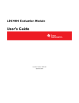
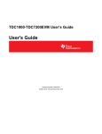
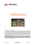
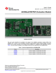
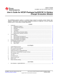
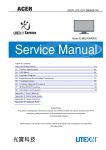
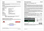
LDC1000 Evaluation Module
User's Guide
Literature Number: SNAU150
September 2013
Chapter 1
SNAU150 – September 2013
LDC1000 Evaluation Module
1.1
Overview
The LDC1000 Evaluation Module is designed to provide an example LC tank and coil structure
application, to interface to a host computer. The module can be used independently of the GUI by the onboard embedded LED, which demonstrates threshold detection.
Figure 1-1. Evaluation Module
The EVM includes an example PCB sensor which is 14mm in diameter and contains 2 layers. A 100pF
1% COG cap is connected, in parallel, to the PCB coil, in order to form an LC tank.
The EVM is perforated at two locations: One between Coil and LDC1000, which provides the option to
snap the PCB coil and connect a custom coil required in the application. The second perforation is
between LDC1000 and MSP430, and provides the option to connect the LDC1000+Sensor into a different
system or use multiple of such sensors in one system for prototyping.
Figure 1-2. LDC1000+Sensor
When the evaluation module first powers up from the USB port, it will flash a series of green and red LED
lights to indicate self-test. When self-test is finished, the green LED indicates the status of the LDC1000
INT pin. When INT is asserted, the green LED is lit. By default, INT is configured for threshold detection.
2
LDC1000 Evaluation Module
SNAU150 – September 2013
Submit Documentation Feedback
Copyright © 2013, Texas Instruments Incorporated
Chapter 2
SNAU150 – September 2013
Quick Start Guide LDC1000 Evaluation Module
2.1
LDC1000 Evaluation Module Overview
The LDC1000 Evaluation Module (EVM) enables the user to test out analog and digital capabilities of the
LDC1000 Inductance-to-Digital Converter. The EVM is a USB device used with a host computer and
accessed using the Inductive Sensing Graphical User Interface (GUI) software, which is documented in
Chapter 3.
To quickly get started on the LDC1000 GUI, follow the steps below to load and configure a device.
2.1.1 Evaluation Module
Set Up Requirements
1. The LDC1000 GUI and drivers must be installed on the host.
2. The USB port of the EVM must be connected to the host.
Loading and Running
1. Plug the EVM into the host computer. The host computer should automatically detect the device as
LDC1000EVM.
2. Launch the GUI. It should automatically detect the target, read all the configuration registers, and begin
streaming data.
Figure 2-1. Streaming Section
SNAU150 – September 2013
Submit Documentation Feedback
Quick Start Guide LDC1000 Evaluation Module
Copyright © 2013, Texas Instruments Incorporated
3
LDC1000 Evaluation Module Overview
www.ti.com
Reloading the Device
If the EVM is disconnected from the host at any time, simply reconnect the device and the GUI will
automatically discover and re-establish the streaming abilities with the device.
Configuring the Device Manually
1. The GUI puts the device in streaming mode by default. Click on "Stop" in the Streaming Section to
stop streaming.
Figure 2-2. Stop Streaming
2. Click on the "Configuration Section" icon in the main window toolbar.
Figure 2-3. Configuration Section Icon
3. Select the parameter to change. When entering the comparator thresholds, press ENTER to confirm
the change. Changes are applied immediately.
4
Quick Start Guide LDC1000 Evaluation Module
Copyright © 2013, Texas Instruments Incorporated
SNAU150 – September 2013
Submit Documentation Feedback
LDC1000 Evaluation Module Overview
www.ti.com
Figure 2-4. Configuration Section
Saving Device Configuration
1. Click on the "Save" icon in the toolbar.
Figure 2-5. Save Icon
2. Type a name for the file.
Configuring the Device with Configuration File Defaults
1. The GUI puts the device in streaming mode by default. Click on "Stop" in the Streaming Section to
stop streaming.
2. Click on the "Open" icon in the toolbar.
Figure 2-6. Open Icon
3. Select the configuration file.
SNAU150 – September 2013
Submit Documentation Feedback
Quick Start Guide LDC1000 Evaluation Module
Copyright © 2013, Texas Instruments Incorporated
5
LDC1000 Evaluation Module Overview
www.ti.com
4. After the configuration file is loaded, current values are written once to all supported registers. To
restore defaults defined in the configuration file, click on Restore Defaults to write all current registers
with the new configuration file defaults.
Figure 2-7. Restore Defaults
6
Quick Start Guide LDC1000 Evaluation Module
Copyright © 2013, Texas Instruments Incorporated
SNAU150 – September 2013
Submit Documentation Feedback
Chapter 3
SNAU150 – September 2013
Inductive Sensing GUI User Guide
3.1
Inductive Sensing GUI Overview
The inductive sensing GUI provides graphical configuration and streaming support for the LDC1000. The
GUI package includes drivers for use with the LDC1000 Evaluation Modules (EVM). The EVM
provides a device abstraction layer for the GUI to communicate with the LDC1000 through SPI, and
includes other extended functionality.
3.2
Host platform Requirements
The Inductive Sensing GUI supports:
•
•
32-bit and 64-bit Windows 7
32-bit and 64-bit Windows XP
The host machine is required for device configuration and data streaming.
3.3
EVM Information
For the TI LDC1000 EVM:
•
3.4
The EVM allows the GUI to:
– Configuring register data through SPI (CSB, SCLK, SDO, SDI)
– Stream register data through SPI
– Stream register data through SPI
– Detect interrupts through SPI
Hardware Setup
Below are the steps which are necessary to prepare the EVM for the GUI:
•
•
•
3.5
The GUI must be installed on the host.
The EVM driver must be installed on the host.
The EVM must be connected to a full speed USB port (1.0 or above).
Icon Toolbar
The icon toolbar contains various icons which navigate between sections and perform various functions.
Figure 3-1. Icon Toolbar
SNAU150 – September 2013
Submit Documentation Feedback
Inductive Sensing GUI User Guide
Copyright © 2013, Texas Instruments Incorporated
7
Connecting and Disconnecting
www.ti.com
Name
Description
Connection Information
Indicates whether an EVM is connected to
the PC, and if so, provides details of the
connected device.
Icon
• EVM is connected
• EVM is disconnected
3.6
Open
Opens saved register settings and
defaults
Save
Saves all current register settings and
defaults
Register Settings
Show Register Settings Section
Configuration
Show Configuration Section
Streaming
Show Streaming Section
Connecting and Disconnecting
Device discovery, connection, and disconnection is performed automatically.
3.7
Multiple EVMs
If the user desires to connect to multiple EVMs, multiple instances of the GUI can be launched. Multiple
instances cannot connect to the same EVM; only one instance of the GUI can be connected to one EVM.
3.8
General Configuration
In the configuration section, all registers of the device can be accessed. To access this section, streaming
must be stopped.
8
Inductive Sensing GUI User Guide
SNAU150 – September 2013
Submit Documentation Feedback
Copyright © 2013, Texas Instruments Incorporated
Register Settings
www.ti.com
Figure 3-2. Configuration Section
In the configuration window, select the parameter to change. When entering the comparator thresholds,
press ENTER to confirm the change. Changes are applied immediately.
Press “Read All” to refresh all configuration, status, and data.
Press “Restore Defaults” to write values from the default column (if they exist) to the current register value.
3.9
Register Settings
In the register settings section, all registers of the device can be accessed. To read/write registers,
streaming must be stopped.
SNAU150 – September 2013
Submit Documentation Feedback
Inductive Sensing GUI User Guide
Copyright © 2013, Texas Instruments Incorporated
9
Data Streaming
www.ti.com
Figure 3-3. Register Settings
Double-click on a register in the table to read/write. If a register is read only, the selected register is read
immediately and the table value updated. If the register is read/write, a dialog pops up and the user can
choose a new register value. If the value is not changed, it will default to a read.
Figure 3-4. Read/Write Register Dialog
Press “Read All” to refresh all configuration, status, and data.
Press “Restore Defaults” to write values from the default column (if they exist) to the current register value.
3.10 Data Streaming
Data is streamed from the EVM to the GUI when streaming is started. The sampling rate of the EVM and
the number of samples to plot can be configured.
10
Inductive Sensing GUI User Guide
SNAU150 – September 2013
Submit Documentation Feedback
Copyright © 2013, Texas Instruments Incorporated
Data Streaming
www.ti.com
Figure 3-5. Streaming Configuration
The sampling rate can only be set when streaming is stopped.
3.10.1 Average, Point, Min, Max Values
Average is the default display type. To toggle between sample point, min, and max values, right-click the
display.
Average
The average of all the data points currently in the plot
Point
The newest data point value currently in the plot
Min
The minimum data point value currently in the plot
Max
The maximum data point value currently in the plot
A larger number of samples would result in a larger averaging window.
3.10.2 Zooming and Scaling
Plots are interactive. Zooming options are available by right-clicking the plot and selecting an option from
the context menu.
Figure 3-6. Plot Context Menu
Zoom to...
Zooms to window
Autoscale
Autoscales the data in the plot
Reset
Resets the Zoom window to its default setting
Help
Displays shortcut keys and mouse mappings for scaling and
zooming
SNAU150 – September 2013
Submit Documentation Feedback
Inductive Sensing GUI User Guide
Copyright © 2013, Texas Instruments Incorporated
11
Saving and Loading
www.ti.com
3.10.3 Threshold Display
To display Rp Thresholds, right-click the plot and select “Toggle Markers.”
Figure 3-7. Toggling Markets
3.11 Saving and Loading
3.11.1 Configurations
Configurations can be saved and loaded. To save a configuration, click on the "Save" icon. To load a
configuration, click on the "Open" icon.
Configurations include all register names, current values, and default values. They are saved in CommaSeparated Files (*.csv) and can be modified using a text or spreadsheet editor.
3.11.2 Plot Data
Right-click a plot and select “Save Data…”
Data can be saved to a new file or an existing one. If an existing file is chosen, data will be appended.
12
Inductive Sensing GUI User Guide
SNAU150 – September 2013
Submit Documentation Feedback
Copyright © 2013, Texas Instruments Incorporated
Saving and Loading
www.ti.com
Figure 3-8. Saving Data from a plot
SNAU150 – September 2013
Submit Documentation Feedback
Inductive Sensing GUI User Guide
Copyright © 2013, Texas Instruments Incorporated
13
Chapter 4
SNAU150 – September 2013
Schematics
4.1
LDC1000 Schematics
Figure 4-1. Layout
Figure 4-2. Top Layer
14
Schematics
SNAU150 – September 2013
Submit Documentation Feedback
Copyright © 2013, Texas Instruments Incorporated
LDC1000 Schematics
www.ti.com
Figure 4-3. Bottom Layer
SNAU150 – September 2013
Submit Documentation Feedback
Schematics
Copyright © 2013, Texas Instruments Incorporated
15
Chapter 5
SNAU150 – September 2013
Bill of Materials
Designator
Quantity
Description
Manufacturer
Part Number
C1
1
CAP, CERM, 2.2uF, 10V,
+/-10%, X5R, 0603
Kemet
C0603C225K8PACTU
C2
1
CAP CER 10UF 10V 10%
X5R 0603
TDK Corporation
C1608X5R1A106K080AC
C3, C5, C11, C12, C16,
C19
6
CAP CER 0.1UF 16V 5%
X7R 0402
Murata Electronics North
America
GRM155R71C104JA88D
C4
1
CAP, CERM, 0.01uF,
25V, +/-5%, C0G/NP0,
0603
TDK
C1608C0G1E103J
C6
1
CAP CER 220PF 50V 1%
NP0 0402
TDK Corporation
C1005C0G1H221F050BA
C7
1
CAP, CERM, 2200pF,
50V, +/-10%, X7R, 0603
Kemet
C0603X222K5RACTU
C8, C9
2
CAP CER 18PF 100V 5%
NP0 0603
MuRata
GRM1885C2A180JA01D
C10
1
CAP, CERM, 220pF, 50V,
+/-1%, C0G/NP0, 0603
AVX
06035A221FAT2A
C13, C15
2
CAP, CERM, 1uF, 10V,
+/-10%, X5R, 0402
MuRata
GRM155R61A105KE15D
C14
1
CAP CER 0.056UF 16V
5% X7R 0402
Kemet
C0402C563J4RACTU
C17
1
CAP, CERM, 0.47uF,
10V, +/-10%, X7R, 0603
Kemet
C0603C474K8RACTU
C18
1
CAP CER 20PF 50V 5%
NP0 0805
Kemet
C0805C200J5GACTU
C_Tank
1
CAP CER 100PF 50V 1%
NP0 0603
AVX Corporation
06035A101FAT2A
D1
1
LED SMARTLED GREEN
570NM 0603
OSRAM Opto
Semiconductors Inc
LG L29K-G2J1-24-Z
D2
1
LED 660NM SUPER RED
DIFF 0603SMD
Lumex Opto/Components
Inc
SML-LX0603SRW-TR
D21
1
Diode, Zener, 5.6V,
500mW, SOD-123
Diodes Inc.
MMSZ5232B-7-F
FID1, FID2, FID3
3
Fiducial mark. There is
nothing to buy or mount.
N/A
N/A
J1
1
Connector, USB Type A,
4POS R/A, SMD
Molex
48037-2200
L1
1
INDUCTOR POWER
10UH .45A SMD
TDK Corporation
VLS201610ET-100M
R1, R2
2
RES, 33 ohm, 5%,
0.063W, 0402
Vishay-Dale
CRCW040233R0JNED
R5
1
RES, 33k ohm, 5%,
0.063W, 0402
Vishay-Dale
CRCW040233K0JNED
R6, R7
2
RES 1K OHM 1/10W 5%
0402 SMD
Panasonic Electronic
Components
ERJ-2GEJ102X
R20
1
RES,1M ohm, 5%,
0.063W, 0402
Yageo
RC0402JR-071ML
R40
1
RES 1.5K OHM 1/16W
5% 0402 SMD
Vishay Dale
CRCW04021K50JNED
16
Bill of Materials
SNAU150 – September 2013
Submit Documentation Feedback
Copyright © 2013, Texas Instruments Incorporated
www.ti.com
Designator
Quantity
Description
Manufacturer
Part Number
U1
1
Micropower 150 mA LowNoise Ultra Low-Dropout
Regulator, 5-pin SOT-23,
Pb-Free
Texas Instruments
LP2985AIM5-3.3/NOPB
U2
1
4-CHANNEL ESDPROTECTION ARRAY
FOR HIGH-SPEED DATA
INTERFACES, DRY006A
Texas Instruments
TPD4E004DRY
U3
1
MCU
Texas Instruments
MSP430F5528IRGCR
U4
1
Inductance to Digital
Converter
Texas instruments
LDC1000
Y1
1
CRYSTAL 24.000MHZ
18PF SMD
Abracon Corporation
ABMM-24.000MHZ-B2-T
J2
0
TERM BLOCK 2POS
3.81MM PCB HORIZ
FCI
20020327-D021B01LF
J4
0
Header, TH, 100mil, 2x1,
Gold plated, 230 mil
above insulator
Samtec, Inc.
TSW-102-07-G-S
SNAU150 – September 2013
Submit Documentation Feedback
Bill of Materials
Copyright © 2013, Texas Instruments Incorporated
17
IMPORTANT NOTICE
Texas Instruments Incorporated and its subsidiaries (TI) reserve the right to make corrections, enhancements, improvements and other
changes to its semiconductor products and services per JESD46, latest issue, and to discontinue any product or service per JESD48, latest
issue. Buyers should obtain the latest relevant information before placing orders and should verify that such information is current and
complete. All semiconductor products (also referred to herein as “components”) are sold subject to TI’s terms and conditions of sale
supplied at the time of order acknowledgment.
TI warrants performance of its components to the specifications applicable at the time of sale, in accordance with the warranty in TI’s terms
and conditions of sale of semiconductor products. Testing and other quality control techniques are used to the extent TI deems necessary
to support this warranty. Except where mandated by applicable law, testing of all parameters of each component is not necessarily
performed.
TI assumes no liability for applications assistance or the design of Buyers’ products. Buyers are responsible for their products and
applications using TI components. To minimize the risks associated with Buyers’ products and applications, Buyers should provide
adequate design and operating safeguards.
TI does not warrant or represent that any license, either express or implied, is granted under any patent right, copyright, mask work right, or
other intellectual property right relating to any combination, machine, or process in which TI components or services are used. Information
published by TI regarding third-party products or services does not constitute a license to use such products or services or a warranty or
endorsement thereof. Use of such information may require a license from a third party under the patents or other intellectual property of the
third party, or a license from TI under the patents or other intellectual property of TI.
Reproduction of significant portions of TI information in TI data books or data sheets is permissible only if reproduction is without alteration
and is accompanied by all associated warranties, conditions, limitations, and notices. TI is not responsible or liable for such altered
documentation. Information of third parties may be subject to additional restrictions.
Resale of TI components or services with statements different from or beyond the parameters stated by TI for that component or service
voids all express and any implied warranties for the associated TI component or service and is an unfair and deceptive business practice.
TI is not responsible or liable for any such statements.
Buyer acknowledges and agrees that it is solely responsible for compliance with all legal, regulatory and safety-related requirements
concerning its products, and any use of TI components in its applications, notwithstanding any applications-related information or support
that may be provided by TI. Buyer represents and agrees that it has all the necessary expertise to create and implement safeguards which
anticipate dangerous consequences of failures, monitor failures and their consequences, lessen the likelihood of failures that might cause
harm and take appropriate remedial actions. Buyer will fully indemnify TI and its representatives against any damages arising out of the use
of any TI components in safety-critical applications.
In some cases, TI components may be promoted specifically to facilitate safety-related applications. With such components, TI’s goal is to
help enable customers to design and create their own end-product solutions that meet applicable functional safety standards and
requirements. Nonetheless, such components are subject to these terms.
No TI components are authorized for use in FDA Class III (or similar life-critical medical equipment) unless authorized officers of the parties
have executed a special agreement specifically governing such use.
Only those TI components which TI has specifically designated as military grade or “enhanced plastic” are designed and intended for use in
military/aerospace applications or environments. Buyer acknowledges and agrees that any military or aerospace use of TI components
which have not been so designated is solely at the Buyer's risk, and that Buyer is solely responsible for compliance with all legal and
regulatory requirements in connection with such use.
TI has specifically designated certain components as meeting ISO/TS16949 requirements, mainly for automotive use. In any case of use of
non-designated products, TI will not be responsible for any failure to meet ISO/TS16949.
Products
Applications
Audio
www.ti.com/audio
Automotive and Transportation
www.ti.com/automotive
Amplifiers
amplifier.ti.com
Communications and Telecom
www.ti.com/communications
Data Converters
dataconverter.ti.com
Computers and Peripherals
www.ti.com/computers
DLP® Products
www.dlp.com
Consumer Electronics
www.ti.com/consumer-apps
DSP
dsp.ti.com
Energy and Lighting
www.ti.com/energy
Clocks and Timers
www.ti.com/clocks
Industrial
www.ti.com/industrial
Interface
interface.ti.com
Medical
www.ti.com/medical
Logic
logic.ti.com
Security
www.ti.com/security
Power Mgmt
power.ti.com
Space, Avionics and Defense
www.ti.com/space-avionics-defense
Microcontrollers
microcontroller.ti.com
Video and Imaging
www.ti.com/video
RFID
www.ti-rfid.com
OMAP Applications Processors
www.ti.com/omap
TI E2E Community
e2e.ti.com
Wireless Connectivity
www.ti.com/wirelessconnectivity
Mailing Address: Texas Instruments, Post Office Box 655303, Dallas, Texas 75265
Copyright © 2013, Texas Instruments Incorporated