1
2. Hardware installation.
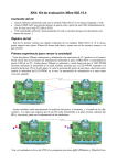
The CIM and Gauges must be connected as shown in the picture below.
For the power you can either use a separate PC power supply or -via an extension cable and free power
connector - the power supply from the PC. The power consumption will vary with the number of units connected.
Roughly each connected G-Step components will draw maximum 50mA from the 5 volts and 20mA from the 12
volts.
Never connect or disconnect gauges while the power
is switched on (this may damage the processor on the
gauge)
On the CIM both voltages are protected via a fuse located closely to the power connector.
The CIM has four mounting holes (each corner), that can be used to mount the CIM.
The mounting holes are connected to ground and can be used to mount the PCB to metal surfaces providing
these are either grounded or “floating”.
To prevent short circuits take care to keep the bottom
side of the PCB free from metal or other conductive
surfaces.
USB is a standard cable from either the PC directly or a USB hub. The little sub-PCB is a converter that
translates the USB interface into serial communication levels as used by the gauges.
The four flat cable connectors on top of the PCB are for connecting the daisy chained gauges. These connectors
are identical and can be used as wanted.
All gauges and G-Step components have two interface connectors. Also these are identical and don’t care which
one you use. We added two connectors per gauge to simplify the daisy chain system. One can be used as the
input from the CIM or another gauge and the other one to connect it with a flat cable to the next one. It is also
4