1
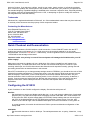
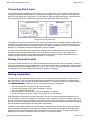
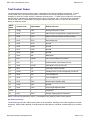
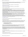
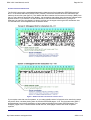
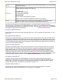
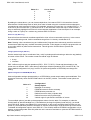
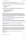
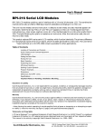
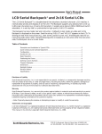
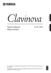
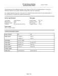
2002-11-13
PRODUKTINFORMATION
Vi reserverar oss mot fel samt förbehåller oss rätten till ändringar utan föregående meddelande
ELFA artikelnr
75-576-22 Grafisk LCD Seriell 120x32
SGX-120L User Manual, rev2.0
Page 1 of 21
120x32-pixel Serial LCD Graphics Module
(G12032)
updated Sept. 26, 2000
The G12032 Serial LCD Graphics Module receives data serially at 2400 or 9600 bits per second (bps) and
displays text and graphics on a 120-by-32-pixel screen. The G12032 supports four font sizes; small, wide,
tall, and large. Depending on the font size selected, the screen can be formatted as:
l
l
l
l
4 lines by 20 characters
4 lines by 10 characters
2 lines by 20 characters
2 lines by 10 characters
Common terminal/printer control codes (such as linefeeds, carriage returns, tabs, backspace, formfeeds)
are supported for easy formatting. Additional instructions permit backlight control, font selection, and
cursor positioning. Graphics instructions plot points, draw lines, and display full-screen images from
nonvolatile memory.
The G12032 (firmware version 030 or higher) has 8kB of nonvolatile EEPROM memory divided into 17
pages of 480 bytes each. The lower two pages of this memory hold the default text font used to display
text. The remaining memory can be used to store up to 15 full-screen images or additional fonts. A utility
program allows you to convert and download bitmapped pictures (120x32-pixel .BMP graphics) to the
display.
G12864 Compatibility. The G12032 is very similar to the larger G12864, but there are some inevitable
differences. If you are familiar with the G12864, check the comparison table in the specifications section
of this document.
Table of Contents
l
l
l
l
l
l
l
l
l
l
l
l
l
l
l
l
Description
Disclaimer of Liability
Warranty, Return/Repair/Replacement Policy
Contacting the Manufacturer
Quick Checkout and Demonstration
Configuring the G12032
Connecting Power
Connecting Serial Input
Display Contrast
Getting Acquainted
Text Control Codes
Graphics Instructions
Painless Graphics Primer
Creating and Downloading Bitmap Fonts and Graphics
Design Notes and Specifications
Recipes and Example Programs
Disclaimer of Liability
Scott Edwards Electronics, Inc. is not responsible for any special, incidental, or consequential damages
resulting from any breach of warranty, or under any legal theory, including lost profits, downtime, goodwill,
damage to or replacement of equipment or property, and any costs or recovering, reprogramming, or
reproducing of data associated with the use of the hardware or software described herein.
Warranty, Return/Repair/Replacement Policy
Scott Edwards Electronics, Inc. warrants this product against defects in materials and workmanship for a
http://www.seetron.com/sgxmnl.htm
2002-11-13
SGX-120L User Manual, rev2.0
Page 2 of 21
period of 90 days. If you discover a defect, we will, at our option, repair, replace, or refund the purchase
price. Return the product with a description of the problem. We will return your product or its replacement
via standard shipping. Expedited shipping is available at the customer's expense. Note: Physically abusing
the module, removing the daughterboard from the LCD, or attempting to repair or modify the module or
the daughterboard, voids this warranty.
Trademarks
Windows® is a registered trademark of Microsoft, Inc. Other trademarked names that may be mentioned
in the body of this document are the property of their respective holders.
Contacting the Manufacturer
Scott Edwards Electronics, Inc.
1939 S. Frontage Road, Suite F
Sierra Vista, AZ 85635 USA
phone: 520-459-4802
fax: 520-459-0623
web: www.seetron.com
email: [email protected]
Quick Checkout and Demonstration
You can demonstrate the G12032 without a serial connection. Put the RUN/SET switch into the SET
position and connect a 9V battery (or 7 to 10Vdc source) to the terminals marked 9V on the serial
daughterboard. Connect the red wire to +. Alternatively, connect regulated 5Vdc to the terminals marked
+5 and GND at the left edge of the board.
Important: make sure polarity is correct! Reversed power will damage the G12032 and/or your 5V
power supply!
With power connected, the display will run a slide show of the factory-loaded font and images in its
EEPROM memory. The slide show demo runs until the unit receives serial input or is shut off. Upon
receiving serial input, the G12032 discontinues the slide show and responds normally, printing text and
processing instructions as described later in this manual.
Since SET mode allows you to change startup settings stored in EEPROM, you should set the unit to RUN
mode before sending serial data to it. Disconnect power, move the switch to RUN, and reconnect power.
With the display in RUN mode, connect serial input to the terminals marked SER and GND. Set your
terminal software to 2400 or 9600 bps (matching switch 2 on the G12032 ) with no parity, 8 data bits, 1
stop bit. Connect power and type some text. Browse this manual and try typing the various text and
graphics instructions. See the Recipes section for exercises that explore some of the display's
capabilities.
Configuring the G12032
A pair of switches on the G12032 configure the display. Set switches with power off.
Run/Set:
Set the display to receive and display serial data (run), or to cycle through a slide show of preloaded
graphics (set). The slide show stops when the display receives serial data. SET mode enables use
of the instruction ESC-W (write startup data to EEPROM). Startup settings that can be configured
with ESC-W include backlight on/off, EEPROM write protection, startup screen, font size, and
location of the vertical origin. See the detailed description for further information on using ESC-W.
In normal operation, this switch should be set to RUN to prevent accidental reconfiguration of the
startup data.
2400/9600:
Set the serial data rate to 2400 or 9600 bps. The serial parameters are: no parity, 8 data bits, 1 stop
bit.
http://www.seetron.com/sgxmnl.htm
2002-11-13
SGX-120L User Manual, rev2.0
Page 3 of 21
Figure 1. G12032 connections and configuration switches.
Connecting Power
The G12032 has a built-in voltage regulator. The input is a two-pin connector marked 9V, since a 9V
battery is a suitable power source. With the supplied 9V battery snap, the red wire goes to the + pin. You
also use an adapter or other power supply whose output is 7 to 10Vdc. You may also connect regulated
5VDC power directly to the pins of J1 (the 5-pin connector). The appropriate pins are marked +5V and
GND. Make sure that your power supply is regulated to 5VDC ±0.25V and is capable of supplying up to 75
mA.
Power Supply Cautions
Do not reverse +5V and GND when supplying 5VDC through J1. These
connections are protected by a shunt diode on the circuit board. A reversed
connection will look like a short-circuit to your power supply and may damage it.
A sufficiently powerful supply connected backwards may destroy the diode and
the display.
Do not exceed 5.5VDC into the +5V input. Overvoltage may damage the display
and/or your power source.
Do not connect anything to +9V (J1 pin 2) when supplying 5VDC through J1 pin 3.
Do not tap into the display's 5-volt supply to power other devices. When the
backlight is turned on, the regulator is near its maximum continuous current
rating.
http://www.seetron.com/sgxmnl.htm
2002-11-13
SGX-120L User Manual, rev2.0
Page 4 of 21
Connecting Serial Input
The G12032 accepts serial data from RS-232 (±10-volt) or logic-level (+5-volt) sources. Although most
serial ports implement additional pins for handshaking purposes, the G12032 requires only the transmit
data (TxD) and signal ground (SG) lines. Connect these to SER and GND respectively. The figure below
shows typical hookups for standard PC-style serial ports and BASIC Stamp computers.
Figure 2. Connecting serial input.
The "loopback" connections shown in the PC comm port hookup serve to disable hardware handshaking.
Our BASIC example programs do not require these connections, but many terminal programs do. If the
software sending data returns a message to the effect of "timed out waiting for port" or "no serial device
detected," the loopback connections will probably cure the problem.
If you are using this display with a single-board computer, see the manufacturer's documentation for
information on connecting serial devices. If the serial output is logic-level (5V), make sure that it is
inverted. In terms of serial communication, this means that the stop-bit condition should be low (0V or
negative) and the start-bit condition should be high (3.5V or higher).
Display Contrast Control
The control marked contrast on the G12032 board sets the initial contrast of the LCD display. Contrast is
factory set, and should not require adjustment. The G12032's temperature-compensation circuit maintains
contrast throughout the operating range of 0° to 50°C (32° to 122°F). You may tweak the contrast setting
by turning this control very slightly while viewing an image on the display.
Getting Acquainted
The best way to get acquainted with the G12032 is to connect power and serial data as outlined in the
previous sections, boot up a terminal program (like the Windows Terminal accessory or Serial Sender
from www.seetron.com), and type some text and instructions. The text you type in your terminal software
will appear on the display. When you set up your terminal program, remember to
l
l
l
l
l
Set the program and the display for the same baud rate.
Configure the program for no parity, 8 data bits, 1 stop bit.
Turn off hardware handshaking.
Set the program for the com port to which the display is connected.
To see your typing on the PC monitor, set the program for "half duplex."
With the display powered and connected, anything you type in the terminal program will appear on the
LCD. If it does not, check the settings and connection. If text is garbled, chances are that the baud rate is
incorrect. As you send text to the display, characters print from left to right. When they reach the end of a
line, the next character appears at the beginning of the next line. When text reaches the end of the display
the next character appears at the top left position of the display.
The layout of the display depends on the font setting. The default font (as set from the factory) uses 6-by8-pixel characters that display in a 4-line-by-20-character format. Bear in mind that all instructions that
position the cursor (printing position) work in terms of the current font--even if a mixture of font sizes is
displayed on the screen. See the font instruction ESC-F for more information.
http://www.seetron.com/sgxmnl.htm
2002-11-13
SGX-120L User Manual, rev2.0
Page 5 of 21
Text Control Codes
The table below lists the text control codes. A separate section lists the graphics instructions. To send
control codes from most terminal programs, hold down the control key and press another key. For
example, to send ctrl-L (clear screen), hold down Ctrl and press L. To send control codes from a program,
transmit a byte containing the appropriate ASCII value. For example, ctrl-L, the clear-screen instruction,
has an ASCII value of 12 (see table). A program would send a byte value of 12 (0C hex or 00001100
binary) to clear the screen.
ASCII
Value
Control Code
ASCII Name
G12032 Function
0
ctrl-@
NUL
Null; ignored prior to buffer
1
ctrl-A
SOH
Send cursor home (position 0, upper left corner)
2
ctrl-B
STX
Begin inverse text (white on black printing)
3
ctrl-C
ETX
End inverse text
4
ctrl-D
ETO
Ignored
5
ctrl-E
ENQ
Ignored
6
ctrl-F
ACK
Ignored
7
ctrl-G
BEL
Ignored
8
ctrl-H
BS
Backspace
9
ctrl-I
HTAB
Tab to next multiple-of-4 column
10
ctrl-J
LF
Smart linefeed; move down one row
11
ctrl-K
VTAB
Vertical tab; move up one row
12
ctrl-L
FF
Formfeed; clear the screen
13
ctrl-M
CR
Carriage return; move to beginning of next line
14
ctrl-N
SO
Turn backlight on
15
ctrl-O
SI
Turn backlight off
16
ctrl-P
DLE
Accept cursor-position data
17
ctrl-Q
DC1
Ignored
18
ctrl-R
DC2
Accept right-alignment data
19-26
-
-
All ignored
27
ctrl-[
ESC
Escape; begin graphics instruction
NOTE: The font-size instruction, ESC-F, is described in the graphics portion of this manual.
Null ASCII 0 (Control-@)
The G12032 ignores nulls without storing them in its data buffer. Sending a null is the equivalent of a brief
time delay. Delay lengths depend on serial speed--at 2400 baud, a null takes 4 milliseconds (ms); at 9600,
1 ms.
http://www.seetron.com/sgxmnl.htm
2002-11-13
SGX-120L User Manual, rev2.0
Page 6 of 21
Home Cursor ASCII 1 (Control-A)
Control-A moves the cursor to position 0 (upper left corner) of the display.
Begin Inverse Text ASCII 2 (Control-B)
Control-B begins inverse printing. Any text printed after ctrl-B will be printed in light pixels on a dark
background. Control-C ends inverse printing.
Cancel Inverse Text ASCII 3 (Control-C)
Control-C cancels inverse-text printing begun with ctrl-B.
Ignored ASCII 4 (Control-D)
Control-D is ignored but takes space in the buffer. Use control-@ if you need a time delay.
Ignored ASCII 5 (Control-E)
Control-E is ignored but takes space in the buffer. Use control-@ if you need a time delay.
Ignored ASCII 6 (Control-F)
Control-F is ignored but takes space in the buffer. Use control-@ if you need a time delay.
Ignored ASCII 7 (Control-G)
Control-G is ignored but takes space in the buffer. Use control-@ if you need a time delay.
Backspace ASCII 8 (Control-H, Bksp Key)
Backspace, which may also be sent as control-H, causes the cursor to back up one column and print a
space, leaving the cursor in that column. Note that backspace works in terms of the font size in effect at
the time that it is received. For example, if the large font is in effect, a backspace will erase an area the
size of one large-font character (12 by 16 pixels). When fonts of different sizes are mixed on the screen,
backspace should be used with caution, since a large backspace would erase several smaller characters.
Horizontal Tab ASCII 9 (Control-I, Tab Key)
Tab, which may also be sent as control-I, causes the cursor to jump to the next multiple-of-four column
position without otherwise affecting the display. For example, if the cursor is at position 0, sending TAB
moves it to position 4. Tabs wrap to the next line, or from the last line back to the first line. When a narrow
(6-pixel) font is in effect, there are 5 tab stops per line; with a wide (12-pixel) font there are 3 tab stops per
line.
Smart Linefeed ASCII 10 (Control-J)
Control-J causes the cursor to drop down to the same column of the next display line. If the cursor is on
the last line, it will wrap to the first line. The linefeed function is smart because it ignores redundant
linefeeds sent immediately after a carriage return. When a short (8-pixel) font is in effect, the display is 4
lines high; with a tall (16-pixel) font, there are 2 lines.
Vertical Tab ASCII 11 (Control-K)
Control-K causes the cursor to move up to the same column of the preceding display line. If the cursor is
on the first line, it will wrap to the last line. When a short (8-pixel) font is in effect, the display is 4 lines
high; with a tall (16-pixel) font, there are 2 lines.
Clear Screen ASCII 12 (Control-L)
Control-L clears the entire screen and moves the cursor to position 0 (upper left corner) of the display.
Return ASCII 13 (Control-M, Return Key)
Return, which may also be sent as control-M, sends the cursor to the first column of the next line of the
http://www.seetron.com/sgxmnl.htm
2002-11-13
SGX-120L User Manual, rev2.0
Page 7 of 21
display. If return is immediately followed by a linefeed, the linefeed will be ignored. When a short (8-pixel)
font is in effect, the display is 4 lines high; with a tall (16-pixel) font, there are 2 lines.
Backlight On ASCII 14 (Control-N)
Control-N turns on the LED backlight, if installed. If not, control-N is ignored.
Backlight Off ASCII 15 (Control-O)
Control-O turns off the LED backlight, if installed. If not, control-O is ignored.
Position Cursor ASCII 16 (Control-P)
Control-P puts the display into cursor-positioning mode. In this mode, there are two ways to move the
cursor to a particular position on the screen:
Text method: Send the display position as text. For example, from a terminal program, press control-P,
then type "13" (just the numbers, not the quotes) followed by a space (to exit the mode). As soon as the
space is typed, the cursor will jump to position 13 (14th character of the first line when the default small
font is in effect). Note that the space (or other non-numeric character other than null) that terminates
position mode is ignored.
One-byte binary method: Send the display position as a single byte value equal to the position plus 64.
For example, from a terminal program, press control-P, then type "A". The cursor will jump to position 1
(second character of the first line) because the ASCII code for A is 65. The G12032 subtracts 64 from the
binary value to arrive at the screen position.
With either method the G12032 will accept values larger than the highest valid screen position for the
current font. The cursor will simply wrap around until it reaches a valid screen position. As with all
instructions that move the printing position, ctrl-P works in terms of the font size in effect at the time. If you
have a mixture of font sizes on the screen, keep this in mind. See the description of the font instruction for
further information on screen layouts with various font sizes.
Ignored ASCII 17 (Control-Q)
Control-Q is ignored but takes space in the buffer. Use control-@ if you need a time delay.
Right Align ASCII 18 (Control-R)
Control-R accepts a number from 2 to 9 (as text) representing the width of an area on the screen in which
right-aligned text is to be printed. The printing position will back up by that number of characters from its
present position. Subsequent text will be stored without printing until one of the following is received:
l
l
l
The specified number of characters
A control character (ASCII 1-31)
A decimal point [the period (.) character]
When one of the conditions listed above is met, the display will print the stored text with right alignment,
erasing any leftover text within the specified width. Note that all of the print-positioning will be done in
terms of the font-size setting in effect at the time the instruction is received.
Note: Right-alignment requires the G12032 to edit incoming data. Bytes sent immediately after exiting the
right-alignment mode may be lost. To prevent this, make sure that your program delays 3-4 milliseconds
after a right-alignment before sending any more data. Or you can add 3 null characters after the character
that ends the right-alignment mode (see list above). The nulls have no effect other than to delay the arrival
of subsequent data.
Ignored ASCII 19-26 (control chars)
ASCII codes 19 through 26 are ignored, but do take space in the buffer. Use control-@ (null) if you need a
time delay.
Graphics Prefix ASCII 27 (Control-[, ESC)
Escape tells the G12032 to expect one of the graphics instructions described in the next section.
http://www.seetron.com/sgxmnl.htm
2002-11-13
SGX-120L User Manual, rev2.0
Page 8 of 21
Printable Characters ASCII 32-191
The G12032 comes with a standard alphanumeric character set (font) loaded into EEPROM screens 0
and 1. In the demo slide show (switch in SET position), the first two screens show the characters that
make up the text font (see figure 3). The utilities disk also contains the font screens in bitmap (.BMP) form
that you may edit and download to the display. Just remember that editing these characters changes what
appears as text. If you edit the A so that it looks like Z and download this altered font, you'll get Z
whenever you send A to the display! It's best to confine your changes to the high-ASCII characters 128191 and leave the normal alphanumeric characters alone.
Figure 3. Default character set stored in screens 0 and 1.
If you require more than one font pattern, or you want to define sets of of symbols to be used in the same
way as the fonts, consider placing them in the other EEPROM pages, 2-16. The font instruction (ESC F,
described later) can instruct the display to fetch character bitmaps from higher EEPROM pages. For
example, pages 0 and 1 could hold the normal text font, while pages 2 and 3 held a set of special
symbols.
http://www.seetron.com/sgxmnl.htm
2002-11-13
SGX-120L User Manual, rev2.0
Page 9 of 21
Graphics Instructions (Escape Sequences)
The table below lists the graphics instructions. These are called escape sequences because they begin
with the escape character (ASCII 27), which distinguishes them from normal text.
All escape sequences follow the same basic pattern: escape-letter-number. For example, the escape
sequence for displaying a screen stored in EEPROM is ESC E n, where n is a number from 0 to 16. From
the keyboard, you would press the Escape key, then E, then a number key like 2, then a non-numeric key
like the space bar. As soon as you press the space bar, EEPROM screen 2 would load into the display.
The final, non-number character in the sequence, the space in our example, is thrown away; it does not
affect the display except to signal the end of the number. Some escape sequences take more than one
number. You can use any non-numeric character other than null (ASCII 0) to separate the numbers. As
we saw in the previous example, the last number must be followed by a non-numeric throwaway
character. Numeric entries are always sent as decimal text, like "123", or one-byte shortcuts.
Numbers up to 191 may be sent as one-byte shortcuts. Just add 64 to the number and send that singlebyte value. For example, to send the number 101, you could either send the three bytes "101" or a single
byte containing the value 64 + 101= 165 (i.e., A5 hex; 10100101 binary). When you send multiple
numbers as shortcuts, you do not need any characters to separate them, nor any throwaway character(s).
Sequence
ESC A x y
ESC B n
ESC D G
ESC E n
ESC F n
ESC I n
ESC L x1 y1 x2 y2
ESC M n
ESC P x y
ESC R n
ESC T x y
Purpose/Effect
Set screen address for next ESC B n to x,y.
Write bit pattern n to current screen address. Screen address is incremented by 1
after write.
Download a 480-byte bitmap graphic.
Display EEPROM screen n (0-16). [NOTE: Earlier models, firmware version 24 and
below, were limited to screens 0-7.]
Set the font size and EEPROM page according to n:
Sizes
0= normal font (6x8 pixels)
1= wide (12x8 pixels)
2= tall (6x16 pixels)
3= wide+tall (12x16 pixels)
EEPROM Pages
0= default, pages 0 & 1
4= pages 2 & 3
8= pages 4 & 5
12= pages 6 & 7
16= pages 8 & 9
20= pages 10 & 11
24= pages 12 & 13
28= pages 14 & 15
(Options can be combined by adding the values above together. Note that earlier
models, firmware 24 and below, were limited to EEPROM pages 0-7.)
Set the ink for points and lines to n, where 0 is white and 1 is black.
Plot a line from coordinates x1 y1 to x2 y2.
Set the graphics drawing mode according to the value of n: 0= OR 1= XOR
Plot a point (pixel) at location x y.
Selectively reverse (invert) 8-pixel high lines of the display according to the value of
n:
0= undo inverted lines
1= line 1 inverted
2= line 2 inverted
4= line 3 inverted
8= line 4 inverted
(Multiple lines can be inverted by adding the values above together.)
Plot a line from last line end to x y.
http://www.seetron.com/sgxmnl.htm
2002-11-13
SGX-120L User Manual, rev2.0
ESC V n
ESC W n
ESC X n
Page 10 of 21
Set vertical origin (y axis 0 point) for plots and lines according to n: 0= top of screen
1= bottom of screen
Write configuration data to EEPROM. Works only with switch in SET position. Sets
startup options according to the value of n:
1= backlight on
2= show screen 2 at start
4= write-protect EEPROM
8= set font wide
16= set font tall
32= set vertical origin (plot/line) to bottom
(Options can be combined by adding the values above together.)
Transfer an image from the screen to EEPROM page (0-16). [NOTE: Earlier
models, firmware version 24 and below, were limited to screens 0-7.]
If you have some experience with bitmapped graphics, you should find the instruction summary
reasonably easy to understand. The startup default settings allow you to get visible results immediately. If
you are unfamiliar with terms like xy coordinates, XOR, etc., see the Painless Graphics Primer that follows
the detailed escape-sequence descriptions.
Set byte-write (A)ddress (ESC A x y)
Set the address for the next byte-write instruction (ESC B n). The x coordinate can range from 0 to 119; y
from 0 to 3.
Write a (B)yte Bit Pattern (ESC B n)
Write the byte value represented by n (0-255) to the current screen address, set by the instruction ESC A
x y. Bytes are treated as vertical columns of bits with the low bit (lsb) at the top. Bits that are set to 1 show
as black pixels; 0s as white. After this instruction, the write-byte address is automatically incremented by
1. If your program requires writing bytes to sequential screen locations (left to right and top to bottom) you
need only to set the starting address.
(D)ownload a Graphic (ESC D G)
Download a bitmapped graphic to the screen. Note that the G in the command is literal; send a capital
letter "G" (ASCII 71) in this position. After this instruction, a program should pause without sending any
further data for 200ms or more. This instruction takes binary data, so it temporarily suspends the
G12032's usual behavior of discarding nulls (ASCII 0). A total of 480 bytes make up a graphic screen.
These bytes map to the screen in exactly the same fashion as those sent via the write-byte instruction,
working left to right and top to bottom. See the Painless Graphics Primer for a map of the graphics screen.
The G12032 starter package includes simple utilities for converting and downloading .BMP files.
Show (E)eprom image (ESC E n)
Transfer a 480-byte image from EEPROM page n to the screen. Valid numbers are 0 through 16.
Whatever is on the screen at the time the ESC E instruction is received is completely replaced by the
stored image. To transfer an image from the screen and into EEPROM, use ESC X. [NOTE: Earlier
models, firmware version 24 and below, were limited to screens 0-7.]
(F)ont Size and Source (ESC F n)
Set the font size and EEPROM page that serves as the source of the font bitmaps. Font size is
determined by the lower two bits (bits 0 and 1) of the value of n as follows:
http://www.seetron.com/sgxmnl.htm
2002-11-13
SGX-120L User Manual, rev2.0
Page 11 of 21
Value of
n
Size
(width x height in
pixels)
0
1
2
3
small (6 x 8)
wide (12 x 8)
tall (6 x 16)
large (12 x 16)
Screen
Organization
(lines x
characters/line)
4 x 20
4 x 10
2 x 20
2 x 10
The figure below shows the effects of font scaling.
Figure 4. Effects of font scaling.
Different font sizes can be freely mixed on the screen. Just remember that all positioning instructions work
in terms of the font size in effect at the time the instruction is received. For example, if a program sends
ctrl-P 9 to move to position 9, it will move to the end of the first line if the wide or large font size is in effect,
or the middle of the first line if small or tall fonts are in effect. The bitmaps (pictures of the individual
characters) that make up the font are nothing more than a pair of ordinary 120x32-pixel graphics.
By default, the G12032 looks at EEPROM pages 0 and 1 as the font. Figure 3 shows how the display
maps portions of those graphics to the printable characters (ASCII values of 32 to 191). If you need more
than 160 characters, you can store the additional bitmaps on the other EEPROM pages and instruct the
G12032 to get characters from those locations. Bits 2 and 3 of n set the font page as follows:
http://www.seetron.com/sgxmnl.htm
2002-11-13
SGX-120L User Manual, rev2.0
Page 12 of 21
Value of n
0
4
8
12
16
20
24
28
Font Location
(EEPROM pages)
0 and 1
2 and 3
4 and 5
6 and 7
8 and 9
10 and 11
12 and 13
14 and 15
To determine the value of n required for a given size and source page, just add the values in the
preceding two tables together. For example, if you want the G12032 to use characters from EEPROM
pages 4 and 5 (n=8) in the tall format (n=2), send ESC F 10. To use the normal page 0/1 font (n=0) in the
small size, send ESC F 0. Note that the default font size the size the G12032 will use after power up and
before receiving any ESC F instructions can be set using the write-configuration instruction ESC W,
described below.
Set (I)nk Color (ESC I n)
Set the color of pixels used in subsequent plot and line instructions to n, where 0 is white and 1 is black.
Draw (L)ine (ESC L x1 y1 x2 y2)
Draw a line from the coordinates x1 y1 to x2 y2 in the current ink color and drawing mode. Valid x
coordinates range from 0-119 and y coordinates 0-31. Drawing lines takes a relatively long time (several
milliseconds) because the G12032 must not only calculate which pixels to set or clear, but must also read,
modify and write many bytes of memory in accordance with the logic of the drawing mode.
Note: Drawing a line can take as long as 6 milliseconds. Programs that continuously send line and line-to
instructions at 9600 bps may overflow the serial input buffer. If this happens, modify the program with one
or two nulls (ASCII 0s) after the line instructions. This will give the G12032 time to process the
instructions.
Set Graphics (M)ode (ESC M n)
Set the logic used to combine new black pixels with old in subsequent plot and line instructions to n,
where 0 is OR and 1 is XOR. Note that this logic is only used in plotting black pixels. If the ink is set to
white, the G12032 unconditionally uses white pixels. (To understand why the mode only applies to black
pixels (represented by logic 1s), remember that ORing and XORing a 0 with another bit leaves that bit
unchanged.) See the Painless Graphics Primer for more information on mode.
Mode does not affect the way that text is printed; text always overprints (erases and replaces) any
previously printed text or graphics. If you want to mix text and graphics in the same screen location (for
example, to draw a line through a word on the screen), print the text first, then apply the graphic.
(P)lot a Point (ESC P x y)
Plots a point at location x,y using the current setting of ink and mode. Valid x coordinates range from 0119 and y coordinates 0-31.
(R)everse Lines (ESC R n)
Reverse/invert (change black to white and white to black) selected 8-pixel-high lines of the display. The
display is 32 pixels tall, so it can be broken into four 8-pixel high lines. The number used with ESC R
determines which of those bands should be inverted as follows:
http://www.seetron.com/sgxmnl.htm
2002-11-13
SGX-120L User Manual, rev2.0
Page 13 of 21
Value of n
0
1
2
4
8
Line to Invert
none
1
2
3
4
By adding the values above, you can invert multiple lines; for instance ESC R 12 inverts lines 3 and 4.
Note that the G12032 keeps track of which lines were inverted using this command so that subsequent
commands can undo previous inversions. For example, suppose you invert line 1 by sending ESC R 1. To
invert line 2 (and un-invert line 1), just send ESC R 2. The instruction works this way in order to make it
easy to selectively highlight lines of text for menu-selection applications. See the recipes for an example.
Using a value of 0 (zero) for n undoes any previous ESC-R inversion.
Draw Line (T)o (ESC T x y)
Draw a line from the last end coordinate specified in a line or line-to command to point x,y in the current
ink color and drawing mode. Valid x coordinates range from 0-119 and y coordinates 0-31.
Note: Drawing a line can take as long as 6 milliseconds. Programs that continuously send line and line-to
instructions at 9600 bps may overflow the serial input buffer. If this happens, modify the program with one
or two nulls (ASCII 0s) after the line instructions. This will give the G12032 time to process the
instructions.
Change (V)ertical Origin (ESC V n)
Set the vertical origin (the 0 coordinate of the y axis) for plotting and line drawing to either the top (default)
or bottom of the screen. The number n sets the vertical origin as follows:
l
l
0= top
1=bottom
ESC V affects only line and plot operations (ESC L, ESC T, ESC P). Points and lines already on the
screen are not affected. ESC V also does not affect byte-oriented operations (ESC A and ESC B). The
factory default configuration is 0 (top), but ESC W (write configuration to EEPROM) can change this
setting.
(W)rite Configuration to EEPROM (ESC W n)
Write configuration settings represented by n to EEPROM to control certain startup options/defaults. This
instruction works only when the SET/RUN switch is in the SET position. The number n sets options as
follows:
Value of n
1
2
4
8
16
32
Configuration/
Startup Option
Backlight on at startup
EEPROM screen 2 shown at startup
EEPROM write protection on
Default font set to wide (12 pixels wide)
Default font set to tall (16 pixels high)
Vertical origin for plot and line at bottom of screen
To set multiple options, just add up the appropriate values from the table. For example, to make the
G12032 start up with the backlight on (1) and default to the large font [wide (8) and tall (16)], you would
send ESC W 25. Options not added into n are turned off, so the screen would be blank at power-up (not
screen 2); EEPROM write protection would be off; and the vertical origin would be at the top of the screen.
To disable all configuration options, send ESC W 0. The G12032 reads its EEPROM configuration only at
startup, so the settings take effect only after the unit is turned off and back on (with the SET/RUN switch in
the RUN position).
http://www.seetron.com/sgxmnl.htm
2002-11-13
SGX-120L User Manual, rev2.0
Page 14 of 21
(X)fer Screen to EEPROM (ESC X n)
Transfer the current screen contents to EEPROM screen n, where n is in the range 0-16. This instruction
may be disabled by the EEPROM-protect configuration setting, written by ESC W above. If this is the
case, ESC X has no effect. To display a screen that has previously been stored in EEPROM, use ESC E.
Be careful with XFERS since EEPROM screens 0 and 1 contain the font bitmaps used to display text. If
you accidentally overwrite these images, text may change to hieroglyphics! You will have to restore the
fonts from the included starter disk.
Note: The G12032's EEPROM can be rewritten at least 1 million times, and read an unlimited number of
times.
Painless Graphics Primer
Here is a quick rundown on the operating principles of the display.
Digital Ink. The LCD is a visible piece of memory. Each pixel is a bit in memory. The color of a pixel is
controlled by the state of the corresponding bit:
0 = white 1 = black
Coordinate System. Memory starts at the upper-lefthand corner of the display with memory address 0.
Byte addresses are numbered sequentially from 0 to 479 left to right and top to bottom. The figure below
shows how rows of bytes in address order correspond to four horizontal stripes of 120 bytes apiece. The
magnified portion of the drawing shows the byte located at xy coordinate 0,0. (In keeping with
mathematical tradition, x is the horizontal coordinate and y is the vertical.) That byte contains 10011111
binary or 159 decimal.
Figure 5. Screen Layout.
The other way to look at the screen is as individual pixels. The only difference from the byte point of view
is the vertical (y) coordinate ranges from 0-31 instead of 0-3. In other words, the screen coordinates for
individual pixels ranges from 0,0 at the upper left corner to 119,31 at the lower right.
The ESC V instruction allows you to flip the vertical coordinates upside down, so that coordinate 0,0 is at
the lower left corner of the screen and 119,31 is at the upper right. ESC V does not affect the byte
coordinate system used with ESC A and ESC B.
Mode Logic. When the G12032 plots points or lines on the screen, it be asked to draw over previously
drawn pixels. Using the mode command you can set the logic it uses to determine how to combine new
and old pixels:
OR (mode 0) Turns white pixels black; black pixels remain black.
XOR (mode 1) Turns white pixels black; black pixels white.
Creating and Downloading Bitmap Fonts and Graphics
The G12032 lets you create and download your own text font and graphics screens. Its 8kB of EEPROM
http://www.seetron.com/sgxmnl.htm
2002-11-13
SGX-120L User Manual, rev2.0
Page 15 of 21
stores the text font and up to 15 full-screen images. This memory is nonvolatile--it retains its contents
even with power removed--but can be rewritten up to 100,000 times.
You can create fonts and images using standard PC-based graphics programs. A Windows conversion
and downloading utility is included with the G12032 disk. The utility handles graphics files in the following
format:
l
l
l
l
Windows bitmap (.bmp) format
Black and white only (1 bit per pixel)
No compression
120 by 32 pixels
This file format is supported by the Windows Paint accessory included with Windows 95 and later. Many
other graphics programs support this format as well. Here's how to set up the Paint accessory:
l
l
l
l
Pull down the Image menu and select Attributes.
Type in a Width of 120 and Height of 32.
Under Units click on Pels.
Under Colors click on Black and white.
When you're done, click OK.
The Paint accessory is a good choice for creating and editing these images, because it lets you work
pixel-by-pixel, and can display a grid and/or xy coordinates. You can import pictures from most other
programs via cut and paste. The disk that comes with the starter kit contains the standard font and a set
of sample images. An easy way to get started is to open one of these files with Paint, modify it, and save it
under a different file name. Don't use any other format or settings. The utility will download gibberish to the
display, as it cannot recognize or convert other formats. Check the file size--it will be always be 574 bytes
for a 120x32 uncompressed black-and-white BMP file.
Hint: If you used an upscale graphics program (e.g., Photoshop) to create the file and the file size is
slightly off, you can correct this by opening the file with Paint and resaving it as a standard .BMP file.
Using the Downloading Program
The conversion/downloading program is a simple program that runs under any recent version of Windows
('95 or later). You will find several versions of it on the G12032 disk, named BMP2COM1, BMP2COM2,
etc. The program name indicates the com port that will be used for downloading; BMP2COM2 uses com
2.
Copy the program matching the com port you wish to use to your hard drive. Set the G12032 for 9600 bps
and connect it to the com port. Drag and drop a 120x32-pixel monochrome .BMP file onto the
BMP2COM# program icon.
The program will convert the bitmap file to the correct format for the G12032, then download it to the
display. The program will then ask whether you want to transfer the picture to EEPROM, and if so, to
which location (0-16). If you select 0 or 1, the program will verify that you really want to overwrite the font
memory.
The display will not transfer a picture to EEPROM if the display has been configured for write-protection
via the ESC W instruction. The G12032 is shipped with write protection off to allow users to download
their own graphics. However, you probably should turn write protection on before writing and debugging
programs that send data to the G12032. An out-of-control program could instruct the G12032 to overwrite
its font(s) or other graphics, making it necessary to reload the EEPROM to restore normal operation.
Write-protecting the EEPROM ensures that stored pictures and fonts remain intact regardless of your
program's behavior.
NOTE: Other more elaborate conversion/downloading programs are available from our web site
(www.seetron.com).
http://www.seetron.com/sgxmnl.htm
2002-11-13
SGX-120L User Manual, rev2.0
Page 16 of 21
Font Structure
The text font is stored in the same format as normal full-screen images. It consists of two screens stored
at EEPROM locations 0 and 1. Each character occupies a specific 6- by 8-pixel rectangle of these
screens as shown in figure 3.
If you create your own font, you should probably use this one (files chars0.bmp and chars1.bmp on the
starter disk) as a starting point. Just open the appropriate file with Paint and make your changes.
Design Notes and Specifications
The G12032 is designed to speed prototyping and enable the creation of bench-top instruments requiring
a serially driven text/graphics display. It is not meant for direct use by non-technical users or for
incorporation into mass-produced consumer equipment. It has not been tested to EMC/EMI/ESD
standards. (The same is true of most single-board computers and other subassemblies whose specs do
not specifically include compliance data.) It is up to the purchaser to determine whether the G12032 is
suitable for the intended use.
This unit is designed and manufactured to high standards of quality. This notice is simply intended to head
off invalid assumptions that might affect decisions about using the G12032 in consumer products.
Differences from the G12864
The G12032 is similar to the G12864 graphics display. There are a few differences:
Feature
G12032
G12864
Size in pixels (horizontal x vertical)
120x32
128x64
Separate memory layers for text and graphics
NO
YES
Font layout in pixels (horizontal x vertical)
6x8
8x16
Multiple font sizes
YES
NO
Multiple font pages
YES
NO
Text cursor
NO
YES
Built-in DB9 serial connector
NO
YES
Right-alignment instruction
YES
NO
Configuration switch to flip screen vertically
NO
YES
Serial output
NO
YES
Masked reverse instruction to invert selected lines
YES
NO
Y coordinate flip to place origin at bottom or top of
screen
YES
NO
Unregulated power input
9V battery
AC adapter
NOTE: The G12864 has a minor bug regarding proper termination of decimal numbers. The G12864 is
supposed to discard the 'throwaway' character that follows a decimal number. However, it does not
discard ESC. This means that programs that don't terminate numbers properly, but do send a series of
ESC instructions will work when they shouldn't--the ESC from the next instruction terminates the previous
number and begins a new instruction. The G12032 works exactly as described, and won't let you get away
with improperly terminated numbers. If you port code from the G12864 to the G12032, be on the lookout
for this difference.
http://www.seetron.com/sgxmnl.htm
2002-11-13
SGX-120L User Manual, rev2.0
Page 17 of 21
Maximum Ratings and Electrical Characteristics
The following data is preliminary and subject to change without notice. The G12032 consists of two
subassemblies--an LCD graphics module, and a custom serial controller. Where the ratings of these two
devices vary, the more conservative rating is shown in the table.
Parameter
Operating temperature range
min
max
typical
unit
0
+50
-
°C;
+32
+122
-
°F;
20
+70
-
°C;
4
+158
-
°F;
7.0
12.0
9.0
Vdc
Supply voltage to J1 ("5V")
4.50
5.50
5.00
Vdc
*Current draw, backlight off
-
20
10
mA
*Current draw, backlight on
-
60
40
mA
Input voltage, serial 1
-15
+0.5
-
V
Input voltage, serial 0
3
15
-
V
Processor clock speed
-
-
16
MHz
Storage temperature range
Supply voltage to J2 ("9VDC")
*Note: Current draw specs apply to the 5V supply. Current drawn through the "9V"
connector is approximately 10mA higher.
Maximum Execution Times for LCD Instructions
The following data is preliminary and subject to change without notice. Instructions not listed in this table
take less than 1 ms and therefore do not cause data to accumulate in the serial input buffer. The buffer
can hold a maximum of 64 bytes. All times are measured from entry of the last instruction parameter to
the processing of the next instruction.
Instruction/action
max
units
Display a text character (ASCII 32-191)
0.8
ms
Clear screen (ctrl-L)
20
ms
EEPROM screen (ESC E)
25
ms
Line plot (ESC L or ESC T)
6
ms
100
ms
Transfer a screen to EEPROM (ESC X)
Mechanical Specifications
http://www.seetron.com/sgxmnl.htm
2002-11-13
SGX-120L User Manual, rev2.0
Page 18 of 21
A
y offset edge to hole center (top & bottom)
B
y pcb height
36.00
C
y hole spacing
28.00
D
y screen opening
18.50
E1
y character size (small font)
3.92
E2
y character size (large font)
7.84
F1
x character size (small font)
2.94
F2
x character size (large font)
5.88
G1
x offset pcb edge to hole center (bottom)
2.50
G2
x offset pcb edge to hole center (top)
4.00
H
x screen frame
65.70
I
x screen opening
60.50
J1
x hole spacing (bottom)
75.00
J2
x hole spacing (top)
72.00
K
x pcb width
80.00
L
y frame height
27.40
-
mounting hole diameter
l
l
l
4.00
2.50
All dimensions in millimeters
Tolerance is +/- 0.50mm
Maximum depth (front of screen to highest point on pcb) is 30mm
Handling and Using Liquid Crystal Display Modules
LCDs can be damaged by careless handling. The manufacturer offers these suggestions for safe handling
of LCDs:
l
l
l
l
l
l
l
l
l
l
The LCD module and serial interface electronics use CMOS components and should be handled
with appropriate antistatic precautions.
Do not subject the LCD to temperatures outside its storage/operating ranges. Excessive heat or cold
can degrade the polarizer, cause bubbles in the LCD material, or cause the polarizer to peel.
Do not touch, push or rub the exposed polarizers (transparent screens) with anything harder than an
HB pencil lead (glass, tweezers, etc.). Hard pressure on the screen may distort the liquid-crystal
material. In some cases, the LCD will return to normal with time.
Do not use glue, epoxy, silicone sealant, paint, etc. anywhere on the LCD. These contain solvents or
corrosive substances that degrade contact surfaces over time. They can penetrate the LCD and
damage elastomeric connectors and optical coatings.
When the display surface becomes dusty, wipe gently with absorbent cotton or other soft material
like chamois soaked in petroleum benzine. Do not scrub hard or you may damage the display
surface.
Wipe off saliva or water immediately. Contact with water over a long period of time may cause
deformation or color fading.
Don't allow the LCD to come into contact with oil and fats.
Condensation on the surface and contact terminals due to cold will damage, stain or dirty the
polarizers. After products are exposed to low temperatures they must be allowed to warm up before
coming is contact with room-temperature air.
Do not attach anything to the display screen. This may leave scratches or marks.
Do not touch the display screen with bare hands. This will stain it. Skin oils and cosmetics are
http://www.seetron.com/sgxmnl.htm
2002-11-13
SGX-120L User Manual, rev2.0
l
Page 19 of 21
detrimental to the polarizers.
Do not drop or jar the LCD module as you may crack or chip the glass.
Installing the LCD Module
The LCD manufacturer suggests the mounting arrangement shown below. The protective plate would be a
transparent window; the fitting plate would be the panel or enclosure. The mounting holes accommodate
2/56 machine screws/standoffs. The BEZ-120 mounting kit, available from www.seetron.com, includes a
polycarbonate protective plate and all needed mounting hardware/instructions.
Do not use glue to mount LCDs! Glue, epoxy, silicone sealant, etc. can penetrate and damage delicate
electronics and optics inside the LCD module. Damage by abuse is not covered by warranty.
Recipes and Example Programs
The G12032 accepts standard RS-232-style serial, so it can be used with hundreds of different computers
and dozens of combinations of programming language and operating system. So it's a lost cause to try to
present a comprehensive set of example programs. This disk contains examples in several dialects of
BASIC. Additional examples will be posted at www.seetron.com as they become available.
As a headstart, we recommend that you use a terminal program to try some of the recipes--techniques for
achieving particular effects by manually typing instructions and data. Once you understand the recipes,
you can translate them into the programming language of your choice.
Type the recipes exactly as shown; don't add spaces or returns unless you see [space] or [return]. For
control characters like [ctrl-L] hold down the control key and press another key (L in this case). For Escape
codes, press and release [Esc] then type the other characters specified.
Recipe 1: Positioning the Cursor
This recipe shows how to position the cursor to print changing data without reprinting the entire screen.
Note: the 0 in the [esc] C and F instructions are zeros, not the letter O.
Type this:
Purpose/effect
[cntl-L]
Clear screen
[esc] F 0
Set 4x20 font
RECIPE NUMBER 1 [return]
Text title
Power: [return]
Print label
Speed: [return]
"
[cntl-P]28 [space] 75%
Cursor to position 28; print "75%"
[cntl-P]48 [space] 87 mph
Cursor to position 48; print "87 mph"
[cntl-P]28 [space] 80%
Cursor to position 28; print "80%"
[cntl-P]48 [space] 93 mph
Cursor to position 48; print "93 mph"
[cntl-P]\ 85%
shortcut for "28" is 64+28=92; \ is ASCII 92
http://www.seetron.com/sgxmnl.htm
2002-11-13
SGX-120L User Manual, rev2.0
[cntl-P]p 99 mph
Page 20 of 21
shortcut for "48" is 64+48=112; p is ASCII 112
Note that you can send positions as either number strings like "28" followed by a throwaway character
(like [space]), or as a single byte. The byte value is the number + 64. In the example, 28 is represented by
a byte value of 92, which is the ASCII code for "\". In a program, you'd send a byte value as a byte - an
unsigned char in C, or a CHR$( ) in BASIC.
Recipe 2: Displaying an EEPROM Screen
This recipe shows how to display an image stored in EEPROM and flash the image between normal and
reversed modes. It assumes that the factory-installed screens are still stored in memory. If they are not,
the images displayed will vary from the description.
Type this:
Purpose/effect
[cntl-L]
Clear screen
[esc] E 2 [space]
Show EEPROM image 2 (G12032 title screen)
[esc] E 3 [space]
Show EEPROM image 3 ("Intruder Alert")
[esc] R 15 [space]
Reverse (invert) the whole screen
[esc] R 0 [space]
Un-reverse the whole screen
Recipe 3: Combining Font Sizes
This recipe shows how different fonts can be displayed on the same screen. Note that the font size is set
before the screen address input.
Type this:
Purpose/effect
[cntl L]
Clear screen
[esc] F 0 [space]
Set 4x20 font
[cntl-P] 40 [space]
Go to position 1, 3rd line.
Try this cool trick!
Print
[esc] F 3 [space]
Set 2x10 font
[cntl-P] 0 [space]
Go to position 1, 1st line.
WOW!
Print
[ESC] F 1 [space]
Set 4x10 font
[cntl-P] 5 [space]
Go to position 5
MIXED
Print
[cntl-P] 15 [space]
Go to position 15
FONTS
Print
[esc] F 1 [space]
Set 4x10 font
[cntl-P] 31 [space]
Go to position 31
DYNAMITE!
Print
Recipe 4: Selective Highlighting
This recipe shows how to use [esc] R to selectively highlight lines of text.
http://www.seetron.com/sgxmnl.htm
2002-11-13
SGX-120L User Manual, rev2.0
Page 21 of 21
Type this:
Purpose/effect
[cntl L]
Clear screen
[esc] F 0 [space]
Set 4x20 font
[space] MENU ITEM 1 [return]
Text
[space] MENU ITEM 2 [return]
Text
[space] MENU ITEM 3 [return]
Text
[space] MENU ITEM 4 [return]
Text
[esc] R 1 [space]
Highlight (reverse) the first line
[esc] R 2 [space]
Highlight (reverse) the second line
[esc] R 4 [space]
Highlight (reverse) the third line
[esc] R 8 [space]
Highlight (reverse) the fourth line
Recipe 5: Drawing a Box
This recipe shows how to use the line and line-to instructions.
Type this:
Purpose/effect
[cntl L]
Clear screen
[esc] L 5,2,114,2[space]
Draw a line from xy coords 5,2 to 114,2
[esc] T 114,27[space]
Draw a line to xy coords 114,27
[esc] T 5,27[space]
Draw a line to xy coords 1,27
[esc] T 5,2[space]
Draw a line to xy coords 5,2 (completes box)
That example has you enter the coordinates as number strings followed by a throwaway character
[space]. You can also send data as a one-byte shortcut by adding 64 to the desired coordinate. The byte
value is the number + 64. In the following example, 10 is represented by a byte value of 74, which is the
ASCII code for "J". In a program, you'd send a byte value as a byte - an unsigned char in C, or a CHR$( )
in BASIC. Any number up to 191 can be sent as a one-byte shortcut. Here's an example that uses
shortcuts:
Type this:
Purpose/effect
[cntl L]
Clear screen
[esc] LJJzJ
Draw a line from xy coords 10,10 to 58,10
[esc] TzV
Draw a line to xy coords 58,22
[esc] TJV
Draw a line to xy coords 10,22
[esc] TJJ
Draw a line to xy coords 10,10 (completes box)
http://www.seetron.com/sgxmnl.htm
2002-11-13