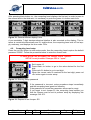
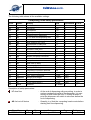
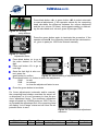
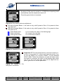
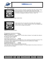
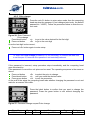
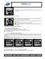
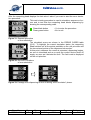
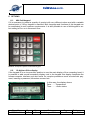
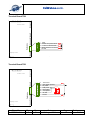
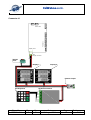
1
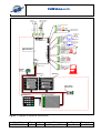
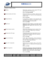
EsiWelma s.r.l. TW1-B Computing Head User Guide Gasoline version EsiWelma s.r.l. Via F.lli Canepa 134d-e 16010 Serra Riccó (Genoa) ITALY Tel: +39 010 754211 Fax: +39 010 7542178 email: [email protected] Type / No. EW055. 601 Rev. C Fw D Date 05 August 2011 Page 1 Total pages 40 EsiWelma s.r.l. CONTENTS 1. TECHNICAL DESCRIPTION-------------------------------------------------------------------------- 4 1.1. Structural specifications ---------------------------------------------------------------------- 4 1.2. Technical specifications----------------------------------------------------------------------- 4 2. FUNCTIONAL DESCRIPTION ----------------------------------------------------------------------- 6 2.1. Display ---------------------------------------------------------------------------------------------- 6 2.2. Description of operating sequences ------------------------------------------------------ 6 2.2.1. Manual dispensing --------------------------------------------------------------------- 8 2.2.2. Pre-set value dispensing ------------------------------------------------------------- 8 2.2.3. Pre-setting the volume on the dispenser --------------------------------------- 8 2.2.4. Pre-setting by Host --------------------------------------------------------------------- 9 2.2.5. Pre-setting by 16-key keypad ------------------------------------------------------- 9 2.2.6. Automatic stop sequence ------------------------------------------------------------ 9 2.2.7. Stop at round figure------------------------------------------------------------------ 10 2.2.8. Managing a power outage---------------------------------------------------------- 10 2.3. Connection to Host---------------------------------------------------------------------------- 10 2.4. Euro €---------------------------------------------------------------------------------------------- 10 3. TROUBLESHOOTING-------------------------------------------------------------------------------- 11 3.1. Fatal errors--------------------------------------------------------------------------------------- 11 3.2. Non fatal errors --------------------------------------------------------------------------------- 11 3.3. Error review table------------------------------------ Errore. Il segnalibro non è definito. 4. PROCEDURES ----------------------------------------------------------------------------------------- 15 4.1. General totalizer reading -------------------------------------------------------------------- 15 4.2. Computing head setup----------------------------------------------------------------------- 16 4.2.1. Simple parameters-------------------------------------------------------------------- 20 4.2.2. Parameters for volume compensation to temperature ------------------- 20 4.2.3. Complex parameters----------------------------------------------------------------- 20 4.2.4. Password -------------------------------------------------------------------------------- 23 4.2.5. Price change---------------------------------------------------------------------------- 25 4.3. Metric office procedure ---------------------------------------------------------------------- 26 4.3.1. Adjustment factor memory -------------------------------------------------------- 26 5. HARDWARE CUSTOMISING ---------------------------------------------------------------------- 28 6. OPTIONS------------------------------------------------------------------------------------------------- 30 6.1. 4X4 field keypad-------------------------------------------------------------------------------- 30 6.2. 12-digit-on-2-line display -------------------------------------------------------------------- 30 6.3. Abnormality signalling device------------------------------------------------------------- 31 6.4. I/O expansion device ------------------------------------------------------------------------- 31 7. ELECTRICAL CONNECTIONS -------------------------------------------------------------------- 32 7.1. Low Voltage connections ------------------------------------------------------------------- 32 7.2. High Voltage connections ------------------------------------------------------------------ 36 8. IDENTIFICATION OF TW1-B AND TW1NA-B COMPUTING HEAD--------------------- 38 9. MECHANICAL MOUNTING ------------------------------------------------------------------------- 39 10. SEALING PROCEDURE FOR THE TW1-B AND TW1NA-B COMPUTING HEAD -- 40 10.1.CPU sealing plan ----------------------------------------------------------------------------- 40 10.2. Display sealing plan -------------------------------------------------------------------------- 40 Type / No. EW055. 601 Rev. C Fw D Date 05 August 2011 Page 2 Total pages 40 EsiWelma s.r.l. LIST of figures Figure 1: Diagram of electrical connections ...........................................................................................................5 Figure 2: Maximum displayed.................................................................................................................................6 Figure 3: Dispensing start-up sequence.................................................................................................................7 Figure 4: Example of pre-setting 5.00€ ............................................................................................................................ 8 Figure 5: Example of pre-setting 10L .....................................................................................................................8 Figure 6: 16-key keypad .........................................................................................................................................9 Figure 7: Temporary conversion of sale price into Euro.......................................................................................10 Figure 8: Display "Select procedure"....................................................................................................................15 Figure 9: Allotting setup buttons ...........................................................................................................................15 Figure 10: General totalizer display Litres ............................................................................................................16 Figure 11: Entering Setup password ....................................................................................................................16 Figure 12: Request to set Jumper JP2 .................................................................................................................16 Figure 13: Display of some setup parameters .................................................................................................20 Figure 14: Display Density....................................................................................................................................20 Figure 15: Display initial AdJ Pulse ......................................................................................................................20 Figure 16: Allotting setup buttons ....................................................................................................................21 Figure 17: Display Adjustment factor....................................................................................................................21 Figure 18: Manual setting of adjustment factor ....................................................................................................21 Figure 19: Error exceeds adjustment maximum...................................................................................................21 Figure 20: Error below minimum adjustment........................................................................................................22 Figure 21: Example of P1 and P2 value in Euro ..................................................................................................22 Figure 22: Display of Currency/Euro conversion..................................................................................................22 Figure 23: Password change request setup.........................................................................................................23 Figure 24: Data saving display .............................................................................................................................23 Figure 25: Change Password ...............................................................................................................................24 Figure 26: Enter Password ...................................................................................................................................25 Figure 27: Password change request Price change.............................................................................................25 Figure 28: Display of unit price saving..................................................................................................................26 Figure 29: Password change Price change..........................................................................................................26 Figure 30: Sequence of adjustment factor display ...............................................................................................26 Figure 31: Request procedure..............................................................................................................................27 Figure 32: Exit from Procedure.............................................................................................................................27 Figure 33: Passage from dispensing to shut off during "error simulation” phase.................................................27 Figure 34: Identification plate for TW1-B; “Standard”...........................................................................................38 Figure 35: Identification plate for TW1nA-B; “Atex”..............................................................................................38 Figure 36: CPU enclosure mounting ....................................................................................................................39 Figure 37: Display enclosure mounting ................................................................................................................39 LIST of photos Photo 1: CPU..........................................................................................................................................................4 Photo 2: Setup / Price change................................................................................................................................4 Photo 3: Display......................................................................................................................................................4 Photo 4: Jumpers on CPU....................................................................................................................................28 Photo 5: Example of preset customised keypad ..................................................................................................30 Photo 6: Secondary display..................................................................................................................................30 Photo 7: Abnormality signalling device.................................................................................................................31 Photo 8: I/O expansion device..............................................................................................................................31 Photo 9: Identification plate on electronic computing head TW1 .........................................................................38 Photo 10: Computing head CPU TW1-B and TW1nA-B ......................................................................................40 Photo 11: Display of computing head TW1-B and TW1nA-B front view ..............................................................40 Photo 12: Display of computing head TW1-B and TW1nA-B rear view ...............................................................40 Photo 13: Display for computing head TW1-B and TW1nA-B rear view neon tube backlit version....................40 Type / No. EW055. 601 Rev. C Fw D Date 05 August 2011 Page 3 Total pages 40 EsiWelma s.r.l. 1. TECHNICAL DESCRIPTION The TW1-B electronic computing head is designed to operate on single-nozzle fuel dispensers. One or two-sided display systems can be used. It can supply in both Euro and litre system pre-setting. It can communicate with a Host sending data concerning the refuelling during the process and/or at the time of the device. 1.1. Structural specifications The computing head is made up of: a CPU board complete with power supply and communication interface. The board is housed in a metal enclosure that protects it mechanically and against EMI jamming. Photo 1: CPU a price change / setup board in a plastic enclosure. The assembly can be housed where the user desires, or inserted only when necessary. one or two display cards, inserted inside a metal enclosure. 1.2. Photo 2: Setup / Price change Technical specifications Power supply: 230Vac ± 10% Power consumption: 10VA Temperature: min. –40°C max. 70°C Photo 3: Display Humidity (non condensing): 95% Max flow rate: 3.5l/s Measuring unit: litre Solenoid valve control: N.O. max 270Vca/3A Standard/1A Atex (*) Pulser: 2 channels: 1 pulse = 1cl Protection grade IP20(**) Total counter depending on version: Electromechanical not resetable (7 digit): 1 counting unit = 1l (see Setup) Electronic not resetable (10 digit): 1 counting unit = 1l (see Setup) Dimensions of head CPU: (230 x 154 x 66) mm Weight of head CPU: 1950g Dimensions of head Display: (225 x 250 x 50) mm Weight of head Display: 960g (*) Outputs device depending: Relays for TW1-B “Standard”, or Solid State relays for TW1nA-B “ATEX”. (**) The declared protection grade concerne the metallic box. The devices enclosed by the dotted line in Figure 1 must be installed in a cabinet with at least protection degree IP54, compliant to standard EN60079-15 of ATEX directive. Type / No. EW055. 601 Rev. C Fw D Date 05 August 2011 Page 4 Total pages 40 EsiWelma s.r.l. Red Common Lamps Green Not used in this version 4 EV Blk 3 EV Lf 2 Motor 1 Common hydraulics M All'alimentazione 230Vac o 24Vac TB6 TB7 TB8 TB8 5 1 2 3 Neutral Phase 230Vac o 24Vac Power Supply 1 2 3 Gnd 230Vac Power Supply 6 5 4 3 2 1 TB7 HV connections TB6 0VFld TR2TR2+ 0VFld TR1TR1+ TB4 Computing Head TW1 CPU Board LV connections TB4 MTL 7756ac 7 4 3 5 2 1 MTL 7756ac 7 4 3 Temperature 2 (Optional) TR2 PT100 Temperature 1 8 7 6 5 4 3 2 1 Tank Level ChA pulser repeater 0V pulser ChB pulser ChA pulser +Vcc pulser 0V field Nozzle 5 4 3 2 1 Clear 10.00€/10Litri 5.00€/5Litri € request 0V field 5 4 3 2 1 N.U. Tx Rx 0V field Aut/Man TR1 PT100 TB3 TB3 TB2 Display connection J1 5 2 1 TB2 TB1 J1 Display connector SETUP Card TB1 Display-2 Display-1 L L p.u. p.u. /L /L 4x4 Keyboard Keyboard interface Delete 5 6 Enter 8 9 Euro 0 , Litres 2 4 7 Not Used 1 2 3 4 5 6 7 8 3 1 Abnormality alarm device Figure 1: Diagram of electrical connections Type / No. EW055. 601 Rev. C Fw D Date 05 August 2011 Page 5 Total pages 40 EsiWelma s.r.l. 2. FUNCTIONAL DESCRIPTION 2.1. Display The TW1-B computing head can be used with single-nozzle fuel dispensers. Data is always displayed as follows: 6-digit display for sale price, 5-digit display for the dispensing volume and 4-digit display for unit price. TOTAL AMOUNT L DELIVERED FUEL p.u. /L UNIT PRICE Figure 2: Maximum displayed 25 mm high backlit LCD displays. The backlighting system is formed of a PCB, carrying a LED matrix; it is mounted on the back of the metal enclosure and emits a flooded green light. It is also possible to use a neon-tube system or the lighting of the dispenser itself. 2.2. Description of operating sequences When switched on, the computing head performs some checks: EPROM - it checks the EPROM CRC and compares it with the data shown on the program. RAM - it checks the writing and reading capability of the data RAM. EEROM - it checks the congruence of the data shown in EEROM. DISPLAY - it checks the display connection status. RX-TX - presence of active connection to Host. DATA COMPLIANCE - conformity of the data in RAM with the original data in E²ROM. UNIT PRICE - check that the unit price is not zero. If the above checks give a positive result, before switching off, the display temporarily shows the program code, and immediately after it brings up the last dispensing data. If there are any abnormalities, the display will show the relative error code (if possible). (see Troubleshooting §3.) With the nozzle in place the computing head performs the following checks: DISPLAY TANK LEVEL RAM Type / No. EW055. 601 - it checks the display connection status. - it checks the fuel level in the tank. - it checks the writing and reading capability of the data RAM. Rev. C Fw D Date 05 August 2011 Page 6 Total pages 40 EsiWelma s.r.l. The pump begins dispensing when the nozzle is unhooked: If the dispenser is available, the nozzle can be removed, which will set off the computing head dispensing sequence, performing the following tests: The same ones described above - see §2.2. PULSER - in the event of a pulse measuring device, the presence of pulses is verified in temporal congruence. TOTALIZER - checks the presence of the electromechanical totalizer. FUEL CUT-OFF DEVICE - To make sure the dispenser hose and seal are unimpaired, during the display test described above, the motor starts and checks that the quantity pumped in this phase (AS) does not exceed the quantity programmed; if this occurs the computing head will cut off supply. If the above mentioned checks give a positive result, dispensing can start with a visual control of the display and subsequent activation of the motor and solenoid valves: Display - All digits display 8, followed by Blank then 0.00 Euro and 0.00 litres. Each sequence takes about 1 seconds so the operator can check that each segment is operating correctly, at a glance. L L L p.u. p.u. p.u. /L /L /L Figure 3: Dispensing start-up sequence During dispensing the computing head performs the following functions: Activates command modules on the following devices: motor, solenoid valves and signallights. Acquires pulses from the transducer. One pulse = 1 cl. Calculates and displays the volume dispensed and the sale price. Checks that the data displayed is correct (implicit with RAM and EPROM). Checks that display is operating. Checks the presence and management of electronic and electromechanical totalizer. Checks the power supply on the motor line (motor thermal protection, see §3). Type / No. EW055. 601 Rev. C Fw D Date 05 August 2011 Page 7 Total pages 40 EsiWelma s.r.l. Dispensing ends when: The nozzle is returned to position The pre-set value has been reached The preset quantity/price has been reached Abnormality (see §3). Pulser not operating for longer than set-up time (SE parameter) Block command from Host. …If dispensing stops due to an abnormality the display will show the relative error code (if possible). (see Troubleshooting §3.). 2.2.1. Manual dispensing The operator starts and stops dispensing by removing / replacing the nozzle. 2.2.2. Pre-set value dispensing The head independently cuts off supply when the amount required is reached, whether it has been programmed using the preset buttons or in the event of Host programming. The amount requested is shown as follows: Unit price display Sale price display - Display of volume dispensed - always active. if Euro is selected, the requested value is shown otherwise it is off. if Litres are selected, the requested value is shown otherwise it is off. L L p.u. p.u. /L /L Figure 4: Example of pre-setting Sale price of € 5.00 Figure 5: Example of pre-setting 10 L dispensed 2.2.3. Pre-setting the volume on the dispenser The preset buttons can be used to program the quantity to dispense both as sale price and as volume : Choose whether to operate in Euros or in litres, and the value assigned to the relative button from setup, by following the procedure described below (see § 4.2). To obtain the desired quantity, the relative buttons need to be pressed in sequence. At any time it is possible to view the previous dispensing data by pressing CLEAR. Type / No. EW055. 601 Rev. C Fw D Date 05 August 2011 Page 8 Total pages 40 EsiWelma s.r.l. Position Button 1 Button 2 Button 3 Sale price currency “ € ” 5.00 10.00 CLEAR Volume dispensed “l ” 1.00 10.00 CLEAR The amounts shown in this table are only an example of the sale price and depend on the value assigned to each button during setup phase. The values of the volume dispensed are fixed and cannot be changed. 2.2.4. Pre-setting by Host Each time the computing head is connected to a Host, both with Pre-pay and Post-pay function, it can receive preset values of Euros or litres, without distinction, as long as the POS has this function. No metric parameter can be set from Host The unit price cannot be changed while dispensing 2.2.5. Pre-setting by 16-key keypad When the computing head switches on it carries out a keypad presence check. If this test is positive, the computer manages the keypad to preset a dispensing volume or sale price. 1 2 3 DELETE 4 5 6 ENTER 7 8 9 EURO NOT USED 0 , LITRES Figure 6: 16-key keypad When the nozzle is in place, the keypad is operative and can be used as follows: 1. Pre-set Euro or Litres by pressing the corresponding key. This is obligatory to continue. 2. Press number keys (with comma if necessary) to preset value. 3. Press « ENTER ». The display of the computing head will now show on the corresponding LCD the sale price (top line) or the dispensing volume (middle line) selected. 4. If the value is correct dispensing can begin. If an error occurs, press « DELETE » and repeat steps 1 to 3. The keypad will not work during dispensing. When the nozzle is put back at the end of dispensing, the keypad can be used for a new operation. 2.2.6. Automatic stop sequence Automatic stop occurs in two phases: Flow rate reduction controlled by a solenoid valve. The slow flow offset can be changed from setup (parameter LF), by following the procedure described below (see § 4.2). Motor stop and solenoid valve closure. Type / No. EW055. 601 Rev. C Fw D Date 05 August 2011 Page 9 Total pages 40 EsiWelma s.r.l. 2.2.7. Stop at round figure During dispensing it is possible to stop the current flow at the first round figure from the computing head, as follows: with nozzle off (not in place) and motor operating, press any of the preset buttons, turn on nozzle to start dispensing again. The computing head will stop dispensing at the next Euro or litre. See this sequence in § 2.2.5 2.2.8. Managing a power outage During normal operations, whether or not the dispenser is currently in use, there may be a power surge or outage; if this occurs, the computing head will enter a PWF procedure so it can memorise: sale price, volume dispensed and totalizer. The data is displayed for about 30 minutes after the power fail. The power fail status is shown by the word OFF on the unit price display. When the power supply is restored the memory brings up the last sale data and shows it on the display. 2.3. Connection to Host The computing head has a standard 3-wire connection: TX, RX, Gnd. Other connections are possible by using an adapter card. To use and implement different protocols a licence issued by the owner is required. 2.4. Euro € As described below in §4.2. the computing head can be set up to operate in different currencies; the decimal points can be moved to suit the unit price and the sale price. In any case, the Euro can be configured rapidly by setting Jumper J3; when the computing head starts up it will automatically set the correct decimal points. Furthermore, as required by the standard, in countries that are Ps Ps about to convert to the Euro, after dispensing a volume expressed in local currency, it is L L possible to display the sale price in Euro by temporarily pressing a Ps/L Ps/L dedicated button. p.u. p.u. Figure 7: Temporary conversion of sale price into Euro The standard European rate DGII-C-4(99) is used as the currency conversion rate. Press the button again to switch the display back to the local currency. The computing head will return to standard display automatically when another dispensing process begins. Type / No. EW055. 601 Rev. C Fw D Date 05 August 2011 Page 10 Total pages 40 EsiWelma s.r.l. 3. TROUBLESHOOTING During normal operations, the computing head controls the internal data flow and congruence of the field data. Abnormalities are handled differently according to the damage they may cause to data. The computing head can detect Fatal or non Fatal errors, as described below. In any case, the computing head stops current dispensing, displays the memorised error code and, if connected to Host, communicates the error status. 3.1. Fatal errors These are normally due to malfunctioning which can cause loss of data. In this case, the computing head stops dispensing, displays the corresponding code and does not start-up again. To start-up again it needs to be reset by switching off the power supply for a few seconds. Data congruence EPROM error RAM error EEROM error Totalizer presence error Pulser presence error Intervention of motor thermal protection Vapor recovery 3.2. Non fatal errors All stops caused by an abnormal field status and all stops caused by a temporary operating abnormality caused by a contingent situation such as the lack of unit price, or an occasional situation such as a data invalidated by a disturbance belong to this category. In this case, the error will be automatically deleted as soon as the cause that created it is removed. The computing head will attempt three start-ups; at the fourth unsuccessful attempt the error turns fatal. Display 1 and 2 Communication with Host Setup data loss Tank level Type / No. EW055. 601 Rev. C Pulser channel control LPG temperature sensor out of range Fuel cut-off device Error A.P.I. data table Fw D Date 05 August 2011 Page 11 Total pages 40 Type / No. EW055. 601 Rev. C Fw D Date 05 August 2011 Page 12 [0x37][ 0x31] [0x37][ 0x37] ErAS ErPU [0x34][ 0x33] ErLC [0x34][ 0x37] [0x34][ 0x31] ErSU Erdt [0x38][ 0x30] ErLn [0x34][ 0x36] [0x37][ 0x30] Erd2 ErSt [0x37][ 0x30] Hex [7][1] [4][7] [4][6] [7][7] [4][3] [4][1] [8][0] [7][0] [7][0] Ascii Code protocol [E+][E-] Canale Pulser assente Out-range tab. compensazione Presenza sensore Temperatura Anti Spandimento - Perdita tubo Livello Cisterna Mancanza dati Setup Comunicazione Display 2 Display 1 Description [4][2] [G][0] [0x34][ 0x32] [0x47][ 0x30] FEMF FEPd [0x44][ 0x37] [0x47][ 0x31] FEPU [0x47][ 0x37] FEdt FEAS [G][1] [D][7] [G][7] [3][0] [4][7] [0x34][ 0x37] FEin [0x33][ 0x30] [2][2] [0x32][ 0x32] FEto FECd [1][5] [0x31][ 0x35] [1][0] [0x31][ 0x30] FErA FEEE [1][1] [3][0] [0x33][ 0x30] [0x31][ 0x31] Ascii Hex Code protocol [E+][E-] FEEP FECd Display Code Description Pulser Output after 3 NF errors Out range Tab. after 3 NF errors Anti Spand. after 3 NF errors Data congruence Display after 3 errors NF Mass flow meter control Spare Inputs Totalizer Error Eerom error Ram error EPROM error Data congruence Fatal errors 3.3. Erd1 Display Code Non fatal errors ERRORS REVIEW TABLE EsiWelma s.r.l. Error review table Total pages 40 EsiWelma s.r.l. Description of abnormalities: Display Checks the presence of the single LCD bars and identifies the missing line. Error code: Erd1 or Erd2 Communication with Host Checks that there is a “polling” call from Host at least every 5s. If there is no call, dispensing will be cut off. Error code: ErLn If setup data is missing or not congruent, the computing head does not dispense, forcing the user to insert the missing data. Setup data loss Error code: ErSU Tank level Checks the level sensor; it can stop current dispensing and/or it can wait until the end of dispensing and prevent the next one. (see note) Error code: ErLC Pulser channel control Checks the alternating channel outputs of the Pulser and cuts off dispensing if necessary. Error code: ErPU Checks the temperature detected by the sensor Pt100. This must lie within the operating range (-60°C ÷ +60°C) Temperature off range Error code: ErSt At the start of dispensing, checks that there are no leaks in the hydraulic circuit. If there are leaks, dispensing is blocked. Fuel cut-off device Error code: ErAS Checks that the pointed value in the A.P.I. table is correct; i.e. within the LPG liquid state zone. Error A.P.I. data table Error code: Erdt Checks the congruence of the memorised data. The computing head constantly checks the EPROM and the RAM data, also during dispensing; if there is an error it cuts off supply. Data congruence Error code: FECd Type / No. EW055. 601 Rev. C Fw D Date 05 August 2011 Page 13 Total pages 40 EsiWelma s.r.l. EPROM error The CPU calculates the EPROM checksum and makes sure it is the same as what the EPROM shows. The computing head is blocked if there is an abnormality. Error code: FEEP RAM error With the nozzle in place, the CPU checks the RAM. The computing head is blocked if there is an abnormality. Error code: FErA EEROM error With the nozzle in place, the CPU checks the E²rom. The computing head is blocked if there is an abnormality. Error code: FEEE Totalizer error Checks the presence of the totalizer. The computing head is blocked if there is an abnormality. Error code: FEto Pulser presence error Checks the presence of the Pulser; if it is missing it cuts off supply. Error code: FEPP Intervention of motor thermal protection During dispensing, it checks that there is no intervention of the thermal protection. If thermal protection intervention occurs, dispensing is blocked. Error code: FEHt This error occurs when the fume recovery pump absorbs an even small quantity of liquid. Vapor recovery Error code: FErU NOTE Tank level is a multifunction input. Correctly set the relative paramaters to use it both to detect a level sensor and to cut off supply when the fume recovery system fails. (see computing head setup § 4.2.) Type / No. EW055. 601 Rev. C Fw D Date 05 August 2011 Page 14 Total pages 40 EsiWelma s.r.l. 4. PROCEDURES Apart from normal dispensing three other procedures are available: General totalizer reading Computing head setup (change settings), price change Metric office (simulating abnormalities) To start a procedure just press one of the buttons on the setup board. The display shows the following flashing notice: Press one of the setup buttons to start-up the corresponding procedure; the buttons are on the printed circuit connected to the display cable: L p.u. /L Figure 8: Display "Select procedure" Procedure «black «t» general totalizer reading Procedure «red «S» Computing head setup: change parameters Procedure «green «U» Metric office: simulating abnormalities t S U Figure 9: Allotting setup buttons 4.1. General totalizer reading The general totalizer is a non-settable counter that can be used to store and display the Litres dispensed in 10 digits; since a display with that many digits is not available, digits are broken down into sets and displayed as follows: 1st set 1 digit 0 2nd set 3 digits 000 3rd set 3 digits 000 most significant digit 4th set 3 digits 000 least significant digit 0.000.000.000 Type / No. EW055. 601 Rev. C Fw D Date 05 August 2011 Page 15 Total pages 40 EsiWelma s.r.l. After pressing black button «t», the computing head displays the first set; in order to pass to the second and to the third sets, it is necessary to push the green «U» button each time. L L L L p.u. p.u. p.u. p.u. /L /L /L /L Figure 10: General totalizer display Litres A non-resettable, 7-digit electromechanical totalizer is also mounted on the display. This totalizer is controlled electronically and if it malfunctions, the computing head cuts off fuel supply underway, and displays the error code: FEto. 4.2. Computing head setup Press the red «S» button to enter setup mode; then the computing head requires the default password “20000”. Follow the procedure below to enter the correct code: To enter the SETUP procedure, set Jumper JP2 to "closed". SETUP is not possible if Jumper JP2 is "open". Set Jumper J2 Press black «t» button to go to the value desired for the first digit Press red «S» button to go to next digit When the correct value is reached for the last digit, press red «S» button again to enter setup. L p.u. /L Figure 11: Entering Setup password L p.u. /L If the password is incorrect, setup procedure stops immediately and the computing head goes into stand-by. If the password is correct the parameter values can be reset. If you forget to set Jumper J2, the computing head notifies you that the Jumper must be set to perform setup by displaying this message: Set JP2. Figure 12: Request to set Jumper JP2 Type / No. EW055. 601 Rev. C Fw D Date 05 August 2011 Page 16 Total pages 40 EsiWelma s.r.l. The following table shows all the available settings: Computing head setup parameters Code Abbrev. Meaning Field Incremental U. of m. 01 02 03 04 05 06 07 08 09 10 11 12 13 14 15 16 17 18 19 20 21 LF AS AL Pr EL AP PC BC Ar DP DI Ct LC Nd SE Po Sd AC d t PL Slow flow rate Fuel cut-off LAN address Type of pre-setting Clearance first cl dispensed N° cl in slow flow dispensing start Min. level contact polarity Block mode for min. level Approximation of sale price Decimals in unit price Decimals in sale price Switch to round figure Tank level / Fume recovery Number of displays connected No flow timeout Pos. option Motor start-up delay LPG compensation enabled Density of LPG dispensed Temperature correction detected Declared level protocol 10-90 0-90 1-32 0-2 0-10 0-10 0-1 0-1 0-3 0-3 0-3 1-3 0-1 1-2 1-5 0-1 0-3 0-1 500-655 ±20 1-4 10 3 1 1 1 1 1 1 1 1 1 1 1 1 1 1 1 1 5 1 1 cl cl ------cl cl ------------------------10s ---------g/m³ °C ---- 22 23 24 25 26 CF AdjPulse P1 P2 PnCd Conv. rate of Currency/€ Change pulse weight Pre-set value button 1 Pre-set value button 2 Password 0-9/dig 0- ±20‰ 0-9/dig 0-9/dig X0-X9999 1/dig 1/dig 1/dig 1/dig 1 ------€ or L € or L ---- Description of setup parameters: LF slow flow - At the end of dispensing with pre-setting, in order to reduce mechanical inertia of the dispenser, it is necessary to slow down the flow. LF shows at what cl point the dispenser will switch to slow flow before the end of dispensing. - Quantity in cl that the computing head counts before starting fast flow dispensing. AS fuel cut-off device Type / No. EW055. 601 Rev. C Fw D Date 05 August 2011 Page 17 Total pages 40 EsiWelma s.r.l. AL LAN address - This is the address of the computing head if connected to Host Computer. - The computing head can be preset as follows: 0 no preset 1 preset to Litres 2 preset to Currency - This is the number of cl that may be counted but not shown in the display, at the beginning of each dispensing. - Indicates how many cl are dispensed in slow flow before beginning fast flow dispensing - This indicates if the minimum level alarm status will activate with normally closed or normally open contact. - This indicates whether the minimum level alarm must activate at the end of dispensing (BC=0) or if it can also activate during dispensing (BC=1). - this specifies the type of rounding off: 0 last digit not rounded-off 1 if ld ≥ 5 last digit rounded up 10 if ld < 5 last digit rounded down 0 2 if ld > 0 and ≤ 5 last digit rounded up 5 if ld > 5 and ≤ 9 last digit rounded up 10 3 if pd ≥ 5 last digit rounded up 10 if pd < 5 last digit rounded down 0 where: ld = last digit displayed pd = previous digit - specifies the number of digits to the right of the decimal point (unit price). - specifies the number of digits to the right of the decimal point (sale price). - specifies the type of passage to a round figure: 1 no switch to round figure 2 rounding off units (1.00, 2.00, etc.) 3 rounding off tens (1.00, 2.00, etc.) The position of the decimal point (100 or 10.0 1.00 etc.) makes no difference Pr Type of pre-setting EL cl clearance AP slow flow dispensing PC Min. level BC intervention mode Ar rounding off Dp Decimals in unit price Di Decimals in sale price Ct Switch to round figure LC Tank level / Fume recovery nd number of displays SE no flow timeout Type / No. EW055. 601 Rev. C Fw D - specifies if LC input will be used to detect a tank level or to display the fume recovery system status - specifies the number of displays connected. - specifies, in tens of seconds (from 10 to 50s), the no flow timeout before blocking dispensing; if dispensing is blocked the nozzle must be replaced. Date 05 August 2011 Page 18 Total pages 40 EsiWelma s.r.l. Po Pos. option Sd Start delay AC LPG compensation d Density of LPG t Temperature offset PL Protocol Level CF Currency conversion rate/€ AdjPulse Meter calibration P1 Value assigned to button 1 P2 Value assigned to button 2 - This setting decides how the computing head sends the sale price: 0 sale price X 1 1 sale price X 10 - Specifies the pump start delay: 0 Start when nozzle is extracted 1 Start at the end of blank display (no AS) 2 Start after display time shows 0.00 (no AS) - Enables compensation of the volume in line with the temperature of the LPG dispensed, according to the A.P.I. tables: 0 no compensation 1 volume compensated - Density value of product dispensed. Depends on composition of gas dispensed. The value entered must be between 500 g/m³ and 655 g/m³. (the parameter is only displayed if AC=1) - This can be used to correct the temperature detected the sensor, at steps of 1°C in the field of ±20°C. - It sets the Protocol Level used for communication: 1 Pumalan standard 2 Pumalan (mono + multiproduct + mix) 3 Pumalan esteso (mono + multiproduct + mix) 4 Pumalan like 3 with the totals and data counting Pumalan is a LOGITRON trademark - This is the conversion rate between the local currency and the Euro. - This can be used to calibrate the mechanical counter by changing the pulse weight (nominal: 1 pulse = 1cl). - Preset value used by the computing head when button 1 is pressed. It can be programmed in € or local currency for the amounts. Delivered fuel value is however 1L. - Preset value used by the computing head when button 2 is pressed. It can be programmed in € or local currency for the amounts. Delivered fuel value is however 10L. After the SETUP procedure is completed, set Jumper JP2 to "open" for dispensing. Dispensing is not possible if Jumper JP2 is "closed". Type / No. EW055. 601 Rev. C Fw D Date 05 August 2011 Page 19 Total pages 40 EsiWelma s.r.l. 4.2.1. Simple parameters L L p.u. p.u. /L /L Figure 13: Display of some setup parameters Select the parameter to change (press the green button «U» to change parameter). Press black «t» button to increment the current parameter value. Press red «S» button to clear the current parameter value or set it to the minimum. Press the green button «U» to pass to the next parameter. 4.2.2. Parameters for volume compensation to temperature Volume compensation is intended as the procedure that can be used to change the volume dispensed to suit the temperature and other parameters described below. To compensate the volume, the computing head uses the density of the LPG dispensed, known by its chemical composition (butane, propane and pentane, etc.) and the value of its temperature. The A.P.I. tables memorised give the correction values to apply. The value of the temperature measured by the sensor can be corrected by using the parameter t to adjust the temperature detected by the sensor, at 1°C increments in the ±20°C field. 4.2.3. Complex parameters Some parameters have more digits; in order to change them a different display and procedure is necessary: Parameter d, density of product dispensed; this is used to compensate the volume dispensed. The following sequence is used to set it up: Press black «t» button to increment the density value. Press red button «S» to decrease the value to the minimum. After you set the desired value, press green button «U» to exit the procedure. L p.u. /L Figure 14: Display Density L p.u. /L ADJ Pulse This is the procedure to calibrate the mechanical counter by changing the value of the pulse (rated value: 1 pulse = 1 cl). This procedure is only available in the versions of those countries where this control is allowed. Before entering the procedure, a certain quantity of 20 litres must be dispensed (use a 20 l certified measure for this). Figure 15 shows the display that comes up when you enter the procedure. Figure 15: Display initial AdJ Pulse Type / No. EW055. 601 Rev. C Fw D Date 05 August 2011 Page 20 Total pages 40 EsiWelma s.r.l. A M Figure 16: Allotting setup buttons Press black button «A» or green button «M» to select automatic or manual adjustment. If the operator selects A, the computing head calculates the difference between the volume dispensed and the true volume (20 litres), and suggests adding or subtracting the calculated error volume, given in parts per 1000. Press the green button again to terminate the procedure. If the operator selects M, the computing head allows the calculated error, given in parts per 1000 to be entered manually. L p.u. /L Figure 17: Display Adjustment factor Press black button «t» to go to the value desired for the first digit. L Press red button «S» to go to p.u. next digit. /L Once the last digit is also correct, press the green button to confirm. Figure 18: Manual setting of adjustment factor Press black button «t» button to select the adjustment: SUM to add SUB to subtract === to clear the adjustment factor to zero Press the green button to terminate For future adjustments (automatic and/or manual), the computing head always considers the actual value dispensed, so it is not necessary to clear the previous adjustment factor. The maximum adjustment range accepted is ± 9.99999 parts per 1000. If the error exceeds the adjustment limit, the computing head will display "out of range" status and will clear the adjustment factor to zero. L p.u. /L L p.u. /L Figure 19: Error exceeds adjustment maximum Type / No. EW055. 601 Rev. C Fw D Date 05 August 2011 Page 21 Total pages 40 EsiWelma s.r.l. As above, if the error to correct is <1.00000 the computing head automatically sets the adjustment value to 0. Press the green button to terminate L p.u. /L Figure 20: Error below minimum adjustment P1 value of preset Button 1, this value is only valid if preset to Euro, if it is preset to Litres the value is 1l. P2 value of preset Button 2, this value is only valid if preset to Euro, if it is preset to Litres the value is 10l. Press black button Press red button Press green button «t» to increase the value of the flashing digit. «S» to go to the next digit. «U» to exit the procedure. L L p.u. p.u. /L /L Figure 21: Example of P1 and P2 value in Euro L p.u. /L Parameter CF The conversion factor of the local currency into Euro is composed of 1 whole and 5 decimal points, (e.g. for the old Italian Lira it equals 6.55957), as per standard DGII-C-4(99). Follow this sequence to enter the data: press the button to increment the value of the flashing digit, press red «S» to go to the next digit; when all the digits are set, press green «U» to exit the procedure. Figure 22: Display of Currency/Euro conversion Type / No. EW055. 601 Rev. C Fw D Date 05 August 2011 Page 22 Total pages 40 EsiWelma s.r.l. 4.2.4. Password At the end of the setup the computing head asks whether changing the password or not and waits for an answer Yes or No. Press black button to change the password. Press green button to exit without changing the password. (see § 4. Figure 11) L p.u. /L Figure 23: Password change request setup If the answer is No, the procedure terminates after saving data. If the answer is Yes, a similar sequence to the ones already seen can be used to change the password: L p.u. /L Figure 24: Data saving display The password is structured as follows: Manager password value: 1XXXX This can only be used to change prices. The first value is always 1 and marks the codes reserved for the system manager. The starting value is 10000 Technician password value: 2XXXX This can be used to change all the parameters in the computing head setup procedure. The first value is always 2 and marks the codes reserved for the maintenance company. The starting value is 20000 Importer password value: 3XXXX This can only be used to clear the previous passwords The initial value is wired inside the firmware; it is communicated to the client at the time of sale and cannot be changed. Type / No. EW055. 601 Rev. C Fw D Date 05 August 2011 Page 23 Total pages 40 EsiWelma s.r.l. The password is made up of 5 digits. The first digit shows the access level: Importer, Technician, Manager. Within the procedure, the first digit (access level) cannot be changed so it is not displayed; the other four digits are set by the user. L p.u. /L Press black button «t» to go to the value desired for the first digit. Press red button «S» to go to next digit. Once the last digit is also correct, press the green button to confirm. Figure 25: Change Password To exit the SETUP procedure, reset Jumper JP2 to "open". Dispensing is not possible if Jumper JP2 is "closed" in SETUP. Type / No. EW055. 601 Rev. C Fw D Date 05 August 2011 Page 24 Total pages 40 EsiWelma s.r.l. 4.2.5. Price change Press the red «S» button to enter setup mode; then the computing head requires the password (if not changed previously, the default password is “10000”). Follow the procedure below to enter the correct code: L p.u. /L Figure 26: Enter Password Price change Press black button Press red button «t» «S» to go to the value desired for the first digit to go to the next digit Once the last digit is also correct, Press red «S» button again to enter setup. To enter the Price change procedure it is not necessary to remove the lead seal to set Jumper J2, because this operation is not metrically relevant. If the password is incorrect, setup procedure stops immediately and the computing head goes into stand-by. If the password is correct the unit price can be reset. The operating sequence is the same as above: Press red button Press black button Press green button «S» «t» «U» to select the price to change. until you reach the desired value. to exit the procedure. At the end of the setup the computing head asks whether changing the password or not and waits for an answer Yes or No. L Press the black button to confirm that you want to change the password. Press the green button to exit without changing the password. p.u. /L Figure 27: Password change request Price change Type / No. EW055. 601 Rev. C Fw D Date 05 August 2011 Page 25 Total pages 40 EsiWelma s.r.l. L If the answer is No, the procedure terminates after saving the new unit price. p.u. /L Figure 28: Display of unit price saving If the answer is Yes, a similar sequence to the ones already seen can be used to change the password: Press black button «t» to go to the value desired for the first digit. Press red button «S» to go to next digit. Once the last digit is also correct, press the green button to confirm. L p.u. /L Figure 29: Password change Price change 4.3. Metric office procedure This metric verification procedure is split into two steps: management of the mechanical measurer correction memory simulating errors 4.3.1. Adjustment factor memory Apart from the current factor, the last three adjustment factors used are memorised so it is possible to test any measurement fluctuations caused by temperature or season changes and the like. After entering the procedure, the computing head shows the current factor HISt 0, and the last three factors HISt 1, HISt 2, HISt 3. L L L L p.u. p.u. p.u. p.u. /L /L /L /L Figure 30: Sequence of adjustment factor display Press green button «U» to enter the procedure Continue to press it to continue the display of the values memorised. Type / No. EW055. 601 Rev. C Fw D Date 05 August 2011 Page 26 Total pages 40 EsiWelma s.r.l. After the computing head displays the last value it asks if you want to start the error simulation procedure: This metric testing procedure is used to simulate a sequence of errors and to test that the computing head blocks dispensing by showing the corresponding code. L Press black button Press green button p.u. «Y» to enter the procedure. «N» to exit. /L Figure 31: Request procedure of error simulation L p.u. /L The simulated errors are shown in the ERROR CODES table (§3.3.). To highlight the current simulation status, the computing head switches on all the points available on the unit price bar and the two external points on the dispensed volume bar. At this point, whenever the nozzle is extracted, dispensing begins, an error is simulated and as a result the control device shuts off supply as soon as it detects the fault. The fault code is displayed on the unit price bar. Figure 32: Exit from Procedure of error simulation L L p.u. p.u. /L /L Figure 33: Passage from dispensing to shut off during "error simulation” phase. Type / No. EW055. 601 Rev. C Fw D Date 05 August 2011 Page 27 Total pages 40 EsiWelma s.r.l. 5. HARDWARE CUSTOMISING There are three selectors called JP on the CPU, located inside the enclosure and protected by a metric lead seal, which can be used to change the function of the computing head as follows: JP1 available for future applications JP2 Enables to perform setup operations Open dispensing normal Closed enabled for setup JP3 Forces the computing head to use parameters consistent with Euro, despite the current setup: Open uses the Setup values Closed uses the congruent Euro values VP24 pulser 24V power supply VP12 pulser 12V power supply VP5 pulser 5V power supply JP1 Not used JP3 Open→ Currency Closed → Euro JP4 Open = ChA Pulser JP4 activated low Closed Open =ChA Pulser high = activated ChA Pulser activated low Cl d ChA P l JP5 Open = ChB Pulser activated low Closed =ChB Pulser activated high JP2 Open → Dispensing Closed → Setup JP10 - JP11 Right = Pulse measuring device Left = Modbus measuring device Photo 4: Jumpers on CPU Type / No. EW055. 601 Rev. C Fw D Date 05 August 2011 Page 28 Total pages 40 EsiWelma s.r.l. The Pulser can be configured to the following specifications: Rated power supply voltage: 5V 200mA 12V 100mA 24V 50mA insert the Jumper to position VP5 insert the Jumper to position VP12 insert the Jumper to position VP24 mutually exclusive Type of output: Channel activated low Channel activated high jumper JP4 open jumper JP4 closed The connection terminals of the Pulser must only be used to connect the Pulser. Do not use the power supply or channel terminals for any purposes other than what they are designed for. Type / No. EW055. 601 Rev. C Fw D Date 05 August 2011 Page 29 Total pages 40 EsiWelma s.r.l. 6. OPTIONS 6.1. 4X4 field keypad If it is necessary to preset a quantity of product with very different values and with a variable decimal point, a 16-key keypad is essential. Both language and functions of this keypad can be customised to suit customer requirements. It is also possible to use a field keypad to select setting in Euro or in litres each time. Photo 5: Example of preset customised keypad 6.2. 12-digit-on-2-line display If the keypad is in an inconvenient position to see the main display of the computing head, it is possible to add a small secondary display next to the keypad: this display completes the human-computer interface and also works for complex procedures such as automatic payment, inserting a password, kilometres covered etc. In this case, the display shows: Date.........Temperature Time………Alarm status Photo 6: Secondary display Type / No. EW055. 601 Rev. C Fw D Date 05 August 2011 Page 30 Total pages 40 EsiWelma s.r.l. 6.3. Abnormality signalling device If a detected abnormality has to be shown in remote, a simple device can be used: it is connected to the same flat cable used for display and can be used to activate a free voltage contact in turn used to supply power to a light or any other signalling device. Electrical specifications: Max voltage 270Vca or 350Vdc Output current depending on device used: 3A → Relay (Standard) 1A → Solid state devices (Atex non sparking) Mechanical specifications: Photo 7: Abnormality signalling device Fixing method Overall dimension: Weight: DIN rail 90x35x58mm 60g 6.4. I/O expansion device When the application imposes a test of non-standard apparatus, an I/O expansion device can be used. The board set up for this can read six inputs and route the same number of outputs. The inputs are available on a terminal board. The Open Collector outputs can be connected to the corresponding activation using flat cables. Electrical specifications: INPUT Vmax +5Vdc Imax 1mA OUTPUT Vmax +24Vdc Imax 10mA with open terminal with closed terminal at 0V INPUT OUTPUT non-active output with active output Photo 8: I/O expansion device To use the outputs in environments that pose a hazard to the I/O expansion device, a flat cable can be used to connect an analogue field interface like the one described above (§6.3) with the following specifications: Maximum voltage: 270Vca or 350Vdc Output current: depending on device used: 3A → Relay (Standard) 1A → Solid state devices (Atex non sparking) Type / No. EW055. 601 Rev. C Fw D Date 05 August 2011 Page 31 Total pages 40 EsiWelma s.r.l. 7. ELECTRICAL CONNECTIONS 7.1. Low Voltage connections In general, all tests carried out using micro-switch or buttons are "normally open" and must close at 0V when used. In particular: Nozzle contact is extracted Tank level contact Fume recovery alarm contact Manual / automatic contact Pre-setting buttons Expected pulser open when nozzle is inserted, closed when nozzle changeable in setup as above, instead of Tank level closed in manual, open in automatic normally open, closed in activation Shaft encoder type 01-09 ELTOMATIC Power supply voltage: 4.5-25V current per channel: 60mA outputs: low active pulses: 2x100xlitre WARNING: CAUTION: The cable connection diagrams shown below do not waive the installer from conformity to the local laws. The installer shall also comply with safety regulations in place for the type and specifications of the application, particularly in electrical constructions in potentially explosive atmospheres. Terminal Board TB1 TB8 TB7 Power Links TB6 Protection systems (e.g. zener barriers) and their use depend on the kind of the dispenser and on the classification of the areas which make it up. Field Links TB4 TB3 5 4 3 2 1 TB2 Display Link TB1 Type / No. EW055. 601 Rev. C N.U. Tx Rx 0V field Aut/Man TB1 Fw D Date 05 August 2011 Page 32 Total pages 40 EsiWelma s.r.l. Terminal Board TB2 TB8 TB7 Power Links TB6 Field Links TB4 5 4 3 2 1 TB3 TB2 Display Links Clear 10Litres or € preset value 1Litre or € Preset value Show amount in € currency 0V field TB2 TB1 Terminal Board TB3 TB8 TB7 Power Links TB6 8 7 6 5 4 3 2 1 Field Links TB4 TB3 Tank Level ChA pulser repeater 0V pulser ChB pulser ChA pulser +Vcc pulser 0V field Nozzle TB3 TB2 Display Links TB1 Type / No. EW055. 601 Rev. C Fw D Date 05 August 2011 Page 33 Total pages 40 EsiWelma s.r.l. Terminal Board TB4 TB8 TB7 Power Links TB6 6 5 4 3 2 1 TB4 Field Links TB4 0VFld TR2TR2+ 0VFld TR1TR1+ 5 2 1 MTL 7756ac Temperature 2 7 Optional 4 TR2 3 PT100 Temperature 1 5 2 1 MTL 7756ac 7 4 3 TR1 PT100 TB3 TB2 Display Links TB1 Terminal Board TB5 Not used in this version Type / No. EW055. 601 Rev. C Fw D Date 05 August 2011 Page 34 Total pages 40 EsiWelma s.r.l. Connector J1 TB8 TB7 Power Links TB6 Field Links TB4 TB3 TB2 Display Links J1 TB1 J1 Display connector SETUP Card Display-2 Display-1 L L p.u. p.u. /L /L 4x4 Keyboard Keyboard interface 2 3 Delete 4 5 6 Enter 7 8 9 Euro Not Used 0 , Litres Rev. C 1 2 3 4 5 6 7 8 1 Type / No. EW055. 601 Faillure Output Fw D Date 05 August 2011 Page 35 Total pages 40 EsiWelma s.r.l. 7.2. High Voltage connections The computing head provides voltage-free contacts that can direct resistive and/or induction loads with the following specifications: Max voltage 270Vca Depending on output devices used: Relay (Standard) Solid state devices (Atex non sparking) → Max current 3A → Max current 1A Terminal Board TB6 5 Not used in this version TB8 TB7 Power Links TB6 4 EV Blk 3 EV Lf 2 Motore 1 Common Hydraulics M Power supply of solenoid valves 230Vac or 24Vac TB6 Field Links TB4 TB3 TB2 Display Links TB1 Type / No. EW055. 601 Rev. C Fw D Date 05 August 2011 Page 36 Total pages 40 EsiWelma s.r.l. Terminal Board TB7 3 Green Lamp 2 Red Lamp 1 Lamp common TB7 TB8 Lamp Power supply 230Vac o 24Vac TB7 Power Links TB6 LV connections TB4 TB3 TB2 Display connection TB1 Terminal Board TB8 3 Gnd 2 Neutral 1 Phase TB8 TB8 TB7 230Vac power supply Power Links TB6 Field Links TB4 TB3 TB2 Display Links TB1 Type / No. EW055. 601 Rev. C Fw D Date 05 August 2011 Page 37 Total pages 40 EsiWelma s.r.l. 8. IDENTIFICATION OF TW1-B and TW1nA-B COMPUTING HEAD A product identification data plate as shown in the figure below is provided, in conformity to standards in force: EsiWelma s.r.l. EsiWelma s.r.l. Via F.lli Canepa 134D-E 16010 Serra Riccò GENOVA (Italia) Certificate of Evaluation: N° LNE-15272 rév.0 Dtd: 13-01-09 Calculator: TW1 - B Style: Standard S/n: ................... Dtd: ............................... Power supply: 230Vac / 50mA Accuracy: 0,5 Unit: Temperature: -40°C+70°C Umidity: 90% Mechanical condition: CLASS M2 Electromagnetic condition: CLASS E2 Via F.lli Canepa 134D-E 16010 Serra Riccò GENOVA (Italia) Certificate of Evaluation: N° LNE-15272 rév.0 Dtd: 13-01-09 Calculator: TW1nA - B Ex nA IIC T4 X Style: S/n: ................... Dtd: ............................... Power supply: 230Vac / 50mA Accuracy: 0,5 Unit: Temperature: -40°C+70°C Umidity: 90% Mechanical condition: CLASS M2 Electromagnetic condition: CLASS E2 l l Figure 34: Identification plate for TW1-B; “Standard” Figure 35: Identification plate for TW1nA-B; “Atex” The identification plate shows the following information: Rated power supply voltage and current consumption: Accuracy Mechanical specifications class Electromagnetic specifications class Device manufacturer Address Evaluation Certificate Device model Application environment Device serial no. and date Photo 9: Identification plate on electronic computing head TW1 Type / No. EW055. 601 Rev. C Fw D Date 05 August 2011 Page 38 Total pages 40 EsiWelma s.r.l. 9. MECHANICAL MOUNTING The computing head CPU is housed in a metal enclosure that can be mounted both vertically and horizontally. Special tabs are included for correct anchorage: For slots for fastening the CPU Figure 36: CPU enclosure mounting The display also has some mounting points. The tabs located in the centre are not mounting points but are dedicated eyelets for the lead sealing. 2 M3 holes for mounting the display 2 Ø 6 holes for mounting the display Figure 37: Display enclosure mounting Type / No. EW055. 601 Rev. C Fw D Date 05 August 2011 Page 39 Total pages 40 EsiWelma s.r.l. 10. SEALING PROCEDURE FOR THE TW1-B and TW1nA-B COMPUTING HEAD 10.1. CPU sealing plan Lead seals that prevent removal of the CPU enclosure and access to the board. Lead seal that prevents removal of the display cable. Lead seals that prevent removal of field connections. Photo 10: Computing head CPU TW1-B and TW1nA-B 10.2. Display sealing plan Lead seal that prevents removal of the display from the dispenser mechanics. Lead seal that prevents access to the display board. Photo 11: Display of computing head TW1-B e TW1nA-B front view Both the right hole and the left hole can be used without distinction. Photo 12: Display of computing head TW1nA-B rear view Lead seal that prevents extraction of the display connection cable. Remarks The spiral that prevents removal of the enclosures (CPU and Display) from the dispenser must be fixed to a part that cannot be moved from the dispenser. Type / No. EW055. 601 Rev. C Fw D Photo 13: Display for computing head TW1-B and TW1nA-B rear view neon tube backlit version. Date 05 August 2011 Page 40 Total pages 40