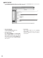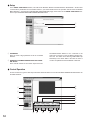
1
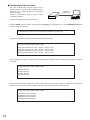
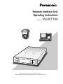
Network Interface Unit
Operating Instructions
Model No.
WJ-NT104
OPERAT
E
LINK
Network
Interface
RCV XMT
Unit WJ-
NT104
Before attempting to connect or operate this product,
please read these instructions carefully and save this manual for future use.
We declare under our sole responsibility that the product to which this
declaration relates is in conformity with the standards or other normative
documents following the provisions of Directives EEC/73/23 and
EEC/89/336.
Vi erklærer os eneansvarlige for, at dette produkt, som denne deklaration omhandler, er i overensstemmelse med standarder eller andre normative dokumenter i følge bestemmelserne i direktivene 73/23/EEC og
89/336/EEC.
Wir erklären in alleiniger Verantwortung, daß das Produkt, auf das sich
diese Erklärung bezieht, mit der folgenden Normen oder normativen
Dokumenten übereinstimmt. Gemäß den Bestimmungen der Richtlinie
73/23/EEC und 89/336/EEC.
Vi deklarerar härmed värt fulla ansvar för att den produkt till vilken
denna deklaration hänvisar är i överensstämmelse med standarddokument, eller andra normativa dokument som framställs i EEC-direktiv nr.
73/23 och 89/336.
Nous déclarons sous note seule responsabilité que le produit auquel se
réfère la présente déclaration est conforme aux normes ou autres documents normatifs conformément aux dispositions des directives
CEE/73/23 et CEE/89/336.
Ilmoitamme yksinomaisella vastuullamme, että tuote, jota tämä ilmoitus
koskee, noudattaa seuraavia standardeja tai muita ohjeellisia asiakirjoja,
jotka noudattavat direktiivien 73/23/EEC ja 89/336/EE. säädöksiä.
Nosotros declaramos bajo nuestra única responsabilidad que el producto a que hace referencia esta declaración está conforme con las normas
u otros documentos normativos siguiendo las estipulaciones de las
directivas CEE/73/23 y CEE/89/336.
Vi erklærer oss alene ansvarlige for at produktet som denne erklæringen
gjelder for, er i overensstemmelse med følgende normer eller andre normgivende dokumenter som følger bestemmelsene i direktivene
73/23/EEC og 89/336/EEC.
Noi dichiariamo sotto nostra esclusiva responsabilità che il prodotto a
cui si riferisce la presente dichiarazione risulta conforme ai seguenti
standard o altri documenti normativi conformi alle disposizioni delle
direttive CEE/73/23 e CEE/89/336.
Wij verklaren als enige aansprakelijke, dat het product waarop deze
verklaring betrekking heeft, voldoet aan de volgende normen of andere
normatieve documenten, overeenkomstig de bepalingen van Richtlijnen
73/23/EEC en 89/336/EEC.
Caution:
Before attempting to connect or operate this product,
please read the label on the bottom.
CAUTION
RISK OF ELECTRIC SHOCK
DO NOT OPEN
CAUTION: TO REDUCE THE RISK OF ELECTRIC SHOCK,
DO NOT REMOVE COVER (OR BACK).
NO USER-SERVICEABLE PARTS INSIDE.
REFER SERVICING TO QUALIFIED SERVICE PERSONNEL.
The lightning flash with arrowhead symbol,
within an equilateral triangle, is interned to
alert the user to the presence of uninsulated
"dangerous voltage" within the product's
enclosure that may be of sufficient magnitude to constitute a risk of electric shock to
persons.
The exclamation point within an equilateral
triangle is intended to alert the user to the
presence of important operating and maintenance (servicing) instructions in the literature accompanying the appliance.
The serial number of this product may be found on the bottom of the unit.
You should note the serial number of this unit in the space
provided and retain this book as a permanent record of your
purchase to aid identification in the event of theft.
Model No.
Serial No.
WARNING:
To reduce the risk of fire or electric shock, do not expose this appliance to rain or moisture.
2
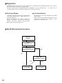
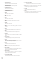
CONTENTS
PREFACE ........................................................................... 4
FEATURES ......................................................................... 4
PRECAUTIONS .................................................................. 5
MAJOR OPERATING CONTROLS AND
THEIR FUNCTIONS ........................................................... 6
■ Front View ................................................................... 6
■ Rear View .................................................................... 6
INSTALLATIONS ................................................................ 8
■ Mounting in the Rack .................................................. 8
SYSTEM CONNECTIONS ................................................. 10
■ LAN Type Connection ................................................ 10
■ PPP (Point to Point Protocol) Type Connection .......... 11
PREPARATIONS ............................................................... 12
■ LAN Type Connection ................................................ 12
■ WJ-NT104 Setup ........................................................ 15
■ PPP Type Connection 1 (P to P ACCESS) ................. 16
■ PPP Type Connection 2 (NETWORK ACCESS) ......... 22
MAIN PAGE AND CONTROLS ......................................... 25
■ Main Page and Control Windows ............................... 25
■ Operation Modes ....................................................... 26
■ Pull Mode and Push Mode ......................................... 28
■ Picture Quality Setup ................................................. 29
■ MAIN PAGE (without Camera Control) ...................... 30
■ MAIN PAGE (with Camera Control) ........................... 32
ALARM FUNCTION .......................................................... 37
■ ALARM LIST Window ................................................. 37
■ ALARM Recording ..................................................... 38
■ ALARM NOTICE ......................................................... 39
■ Alarm Image Readout ................................................ 39
SETUP PROCEDURES ..................................................... 40
■ How to Read ADMINISTRATOR SETUP PAGE .......... 40
■ MODE SETUP ............................................................ 41
■ NETWORK SETUP ..................................................... 43
3
■ ALARM SETUP ........................................................... 44
■ SERIAL PORT SETUP ................................................ 46
■ MODEM SETUP ......................................................... 47
■ USER SETUP .............................................................. 48
■ HOST SETUP ............................................................. 49
■ FTP CLIENT SETUP ................................................... 50
■ DATE & TIME SETUP ................................................. 52
■ CAMERA MENU SETUP ............................................. 53
UTILITY SOFTWARE.......................................................... 54
■ Network Setup ............................................................ 54
■ Camera Menu Setup .................................................. 56
ACCESS AUTHORIZATION .............................................. 57
■ Control of Access Authorization ................................. 57
■ Access Level .............................................................. 57
■ Registration .................................................................58
EXTENSION FUNCTIONS.................................................. 59
■ WJ-FS616 Video Multiplexer Control ......................... 59
■ WJ-SX550A/B/C Matrix Switcher Control ................... 61
■ WJ-DR200 AV Disk Recorder Control ........................ 64
■ WJ-HD100 Digital Disk Recorder Control .................. 67
■ WJ-HD500 Digital Disk Recorder Control .................. 69
CONTENTS UPLOAD ....................................................... 72
■ Uploading a File ......................................................... 72
■ Content Storage Memory ........................................... 72
CONTROL BY HTML DESCRIPTION ................................. 73
■ Image Display ............................................................ 73
■ Camera Operation ..................................................... 74
■ Alarm Operation ......................................................... 78
■ Substitute Character Strings in HTTP Server ............. 79
TROUBLESHOOTING ....................................................... 81
PERIPHERALS .................................................................. 82
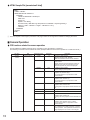
SPECIFICATIONS .............................................................. 83
STANDARD ACCESSORIES ............................................. 83
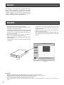
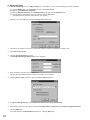
PREFACE
The WJ-NT104 is an interface unit provided with image
capture, JPEG compression and HTTP server functions
enabling it to send analog video output from a video set to
a 10Base-T Ethernet. In a surveillance system it lets you
monitor surveillance pictures on a general purpose PC
using the TCP/IP protocol and a WWW browser.
FEATURES
• Can display images from up to four cameras.
The image of any channel selected on the WJ-NT104 is
displayed on the network monitor.
• Connected to combination cameras of the WV-CS650
or WV-CS850 series (options) via coaxial cables, the
Interface unit can control the pan/tilt head and lens of
the connected cameras.
• Records and transmits images before and after an
alarm in synchronization with an alarm unit.
• Controls CCTV equipment (options) connected via RS232C or RS-485.
Combined with a modem, provides PPP (Point-to-Point)
connections.
• Comes with a home page template which can be customized by rewriting the HTML file using FTP (File
Transfer Protocol).
• Designed for rack mounting using the optional WVQ204/1 mounting brackets.
Use of the optional WV-Q204/2 mounting brackets permits mounting up to two WJ-NT104 units in a rack side
by side.
WJ-NT104
Homepage
Copyrights
•
•
•
•
•
4
MS-DOS is a registered trademark of Microsoft Corporation in the U.S.A. and other countries.
Windows and Windows NT are trademarks of Microsoft Corporation in the U.S.A. and other countries.
Netscape Navigator is a trademark of Netscape Communications Corporation.
Adobe Acrobat Reader is a trademark of Adobe Systems Incorporated.
Other company names and product names appearing in the manual are registered trademarks or trademarks of the companies concerned.
PRECAUTIONS
• Refer all work related to the installation of this product to qualified service personnel or system
installers.
• Do not attempt to disassemble the appliance.
To prevent electric shock, do not remove screws or
covers.
There are no user-serviceable parts inside. Contact
qualified service personnel for maintenance.
• Handle the appliance with care.
Do not strike or shake, as this may damage the appliance.
• Do not expose the appliance to water or moisture,
nor try to operate it in wet areas.
Do take immediate action if the appliance becomes
wet. Turn the power off and refer servicing to qualified
service personnel. Moisture may damage the appliance and also cause electric shock.
5
• Do not use strong or abrasive detergents when
cleaning the appliance body.
Use a dry cloth to clean the appliance when it is dirty.
When the dirt is hard to remove, use a mild detergent
and wipe gently.
• Do not operate the appliance beyond its specified
temperature, humidity or power source ratings.
Do not use the appliance in an extreme environment
where high temperature or high humidity exists.
Use the appliance at temperatures within −10 °C +50 °C (14 °F - 122 °F) and a humidity below 90 %.
The input power source for this appliance is 230 V AC
50 Hz.
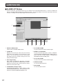
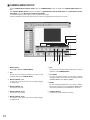
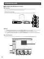
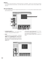
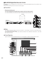
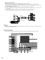
MAJOR OPERATING CONTROLS AND THEIR FUNCTIONS
■ Front View
q
w er
OPERATE
LINK RCV XMT
Network Interface Unit WJ-NT104
t
RESET
OPERATE
RS232C
MODE
LINK RCV XMT
Network Interface Unit WJ-NT104
y
u
i
■ Rear View
o
IN
4
3
!0
2
1
XMT
!1
RCV
!2
SET UP
ALARM
G B A G B
OUT
4
3
VIDEO
2
q Operate indicator [OPERATE]
Is on while the power of the WJ-NT104 is turned on.
w Link indicator [LINK]
Lights when the unit is connected to a normally operating network.
r Transmitting indicator [XMT]
Lights when data is transmitted to the network.
6
RS485
G8 7 6 5G4 3 2 1
DC 12V
IN
1
!3
e Receiving indicator [RCV]
Lights when data is received from the network.
A
RS-232C
!4
10BASE-T
!5
!6 !7
t Front panel
y Reset button [RESET]
Used to set or change a mode, or to restart.
u RS-232C port [RS232]
Used as an alternative to the RS-232C port !4 on the
rear panel.
i Mode selector [MODE]
Used to set a mode.
MODE
Set all the switches to OFF except
when setting a mode.
1 2 3 4 5 6 7 8 9 10
• SW1
To initialize the IP address (IP=192.168.0.10) or
other data already set.
• It takes about 10 seconds after SW1 is set to
ON and the RESET button is pressed for the
data to be initialized.
• After initializing, set SW1 back to OFF and
press the RESET button again to restart.
• SW2
To return the HTML file, JPEG or other image data
stored in the WJ-NT104 to the factory default settings. The IP address and other setup data will not
be initialized.
ON
• It takes a few minutes after SW2 is set to ON
and the RESET button is pressed for the data
to be initialized.
• After initializing, set SW2 back to OFF and
press the RESET button again to restart.
To return all data, including settings and home
page, to the factory default settings, set both SW1
and SW2 to ON and press the RESET button.
• SW3, SW4, SW5, SW6, SW7, SW8, SW10
Keep these in the OFF position.
• SW9
Selects the RS-232C port (front or rear panel).
Setting SW9 to OFF selects the rear panel port,
setting it to ON selects the front panel port.
Switch Positions
SW1
SW2
SW3
SW4
SW5
SW6
SW7
SW8
SW9
SW10
To operate
OFF
OFF
OFF
OFF
OFF
OFF
OFF
OFF
OFF
OFF
To initialize
ON
ON
OFF
OFF
OFF
OFF
OFF
OFF
OFF
OFF
o Video input connectors [VIDEO IN 1/2/3/4] (BNC)
Used to connect cameras.
!5 Ethernet port [10BASE-T]
To connect a 10Base-T cable.
!0 RS-485 connectors [XMT/RCV]
To connect the control data cables of combination
cameras (options)
!6 DC power connector [DC 12V IN]
To connect the AC adapter (accessory).
!1 RS-485 setup switches [RS485 SETUP]
Used when combination cameras with an RS-485 interface are connected.
RS-485 mode
SW1
SW2
SW3
SW4
Half Duplex (2 Lines)/termination ON
ON
ON
ON
ON
Full Duplex (4 Lines)/termination ON
ON
OFF
OFF
ON
Half Duplex (2 Lines)/termination OFF
OFF
ON
ON
ON
Full Duplex (4 Lines)/termination OFF
OFF
OFF
ON
ON
!7 Cord clamp (accessory)
To clamp the cord of the AC adapter (accessory).
Insert the clamp into the hole in the rear panel shown
below.
Cord clamp
ALA
DC1
10BAS
SET UP
ON
12 3 4
!2 Alarm input/output port [ALARM]
To connect an external alarm unit. Input and output can
be changed from the ADMINISTRATOR SETUP PAGE.
!3 Video output connectors [VIDEO OUT 1/2/3/4] (BNC)
The video signal connected to VIDEO IN is looped
through to this connector.
!4 RS-232C port [RS-232C]
To connect a modem or CCTV equipment for controlling the system.
7
RM
2V
E-T
IN
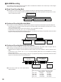
INSTALLATIONS
The installation described below should be made by qualified service personal or system installers.
■ Mounting in a Rack
The WJ-NT104 can be mounted in a rack using the optional WV-Q204/1E mounting brackets.
Use of the optional WV-Q204/2E mounting brackets permits mounting up to two WJ-NT104 units in a rack side by side.
1. Remove the four rubber feet by removing the four screws from the bottom of the WJ-NT104.
Rubber feet
● Mounting one WJ-NT104 with the WV-Q204/1E
2. Fix the mounting brackets (large and small) on both sides of the WJ-NT104 with the eight supplied screws (M3x8) as
shown below.
Rack mounting
bracket (small)
Rack mounting
bracket (large)
● Mounting two WJ-NT104 with the WV-Q204/2E
2. Place the joint metals on the WJ-NT104 units as shown below and fix them with the twelve supplied screws (M3x6)
Note: Remove two screws from the rear of the WJ-NT104 beforehand.
Fix the mounting brackets (small) on both sides of the WJ-NT104 units with the eight supplied screws (M3x8) as shown
below.
Joint metal
Remove 2 screws from
the rear beforehand.
Rack mounting
bracket (small)
Rack mounting
bracket (small)
8
3. Install the WJ-NT104 with the rack mounting brackets in
the rack by using four screws (not included).
Cautions:
• Do not block the ventilation opening or slots in the
cover to prevent the appliance from overheating.
Always keep the temperature in the rack within
+45 °C (122 °F).
• Secure the rear of the appliance to the rack by
using additional mounting brackets (procured
locally) if the rack is subject to vibration.
9
Mounting two WJ-NT104s
Rack mounting screws
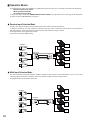
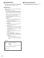
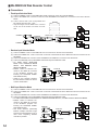
SYSTEM CONNECTIONS
The WJ-NT104 can be operated either in a LAN type connection to an Ethernet or a PPP type connection to a public line via a
modem/terminal adapter (TA).
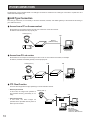
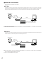
■ LAN Type Connection
For LAN type connection, it is necessary to set the IP address, netmask, and default gateway of the WJ-NT104 according to
your LAN environment.
● Access from a PC on the same subnet
Shown below is an example of direct access from a client PC on the same subnet.
IP address and netmask must be properly set.
Camera (max. 4)
LAN
Ethernet
(10Base-T Cable)
WJ-NT104
PC (browser)
● Access from PCs via routers
Shown below is an example of monitoring from PCs on two or more subnets via routers, for example.
IP address, netmask and default gateway must be properly set.
LAN
LAN
Camera (max. 4)
Router
WJ-NT104
PC (browser)
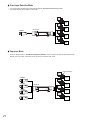
● FTP Client Function
The FTP client supports the image uploading in normal and alarm modes.
• Normal upload mode
Camera (max. 4)
In this mode, the images are uploaded to
the specified directory periodically in normally.
• Alarm upload mode
In this mode, the alarm images are
uploaded to the specified directory when an
alarm input is received.
LAN
LAN
Router
WJ-NT104
PC
FTP Server
*OSs supported
windows, FreeBSD
TurboLinux, Red Hat Linux
10
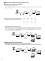
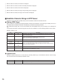
■ PPP (Point to Point Protocol) Type Connection
● Access from a Client PC to the WJ-NT104
• Direct connection to the WJ-NT104
In this configuration, a client PC accesses the WJ-NT104 via a public line using PPP (Point to Point Protocol). With PPP
MODE in the NETWORK SETUP dialog box set to P to P ACCESS, the WJ-NT104 can be accessed by a PC running
Windows95, for example.
RS-232C
cable
RS-232C
cable
Camera (max. 4)
Modem/TA
Modem/TA
WJ-NT104
PC
(Windows 95 etc.)
Public lines
Note: Connection between the WJ-NT104 (DB 9-pin) and
Modem/TA (DB 9-pin or DB 25-pin) are shown figure
below.
DB9
DB25
1 ..................... 8
2 ..................... 3
3 ..................... 2
4 .................... 20
5 ..................... 7
6 ..................... 6
7 ..................... 4
8 ..................... 5
9 .................... 22
DB9
DB9
1 ...................... 1
2 ...................... 2
3 ...................... 3
4 ...................... 4
5 ...................... 5
6 ...................... 6
7 ...................... 7
8 ...................... 8
9 ...................... 9
• Connection via a dial-up server (or a router)
Set an WJ-NT104 telephone number and IP address in the dial-up server (or ISDN, POTS router) in advance. This configuration enables the dial-up server to access the WJ-NT104 using PPP (Point to Point Protocol) when a PC specifies the set
address. With PPP MODE in the NETWORK SETUP dialog box set to NETWORK ACCESS, the WJ-NT104 can be
accessed by a PC running Windows95, for example.
RS-232C
cable
RS-232C
cable
Camera (max. 4)
WJ-NT104
Modem/TA
CSU/DSU
Modem/TA
CSU/DSU
LAN
Dial-up server/
router etc.
Public lines
PC
(Windows95 etc.)
● Access from the WJ-NT104 to a Client PC
Set the telephone number, user name, password, etc. of the client PC in the WJ-NT104.
In this configuration, the WJ-NT104 calls the registered destination and accesses it using PPP (Point to Point Protocol)
when an alarm input is received.
WJ-NT104
RS-232C
cable
RS-232C
cable
LAN
Camera (max. 4)
Modem/TA
Modem/TA
PC (WindowsNT etc.)
Public lines
11
PREPARATIONS
∗ Requires a PC satisfying the following conditions.
• OS: Windows95, Windows98 or Windows NT4.0
• WWW browser active
Recommended browser > Internet Explorer Ver 4.0 or higher
Netscape Navigator Ver. 4.04 or
higher
• Display resolution: 800 x 600 pixels or more
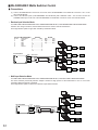
Camera
IN
4
3
2
1
XMT
RCV
SET UP
ALARM
G B A G B
OUT
4
3
VIDEO
2
A
G8 7 6 5G4 3 2 1
RS485
DC 12V
IN
1
10BASE-T
RS−232C
To PC directly or via hub
AC adapter (Accessory)
10Base-T cable
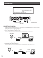
■ LAN Type Connection
The figure below shows how the WJ-NT104 can be connected directly to a PC for testing before it is connected directly to
a network. The connection can also be made via a hub.
● Direct Connection to a PC without Hub
Connect the 10Base-T port on the PC to the Ethernet port on the WJ-NT104 with a crossover cable.
Camera (max. 4)
1
2
3
4
5
6
7
8
1
2
3
4
5
6
7
8
Ethernet crossover cable
WJ-NT104
PC (browser)
● Connection to a Client PC via Hub
Connect the 10Base-T port on the PC to the Ethernet port on the WJ-NT104 with straight cables via a hub.
Camera (max. 4)
Ethernet
straight cable
WJ-NT104
Ethernet
straight cable
Hub
PC (browser)
12
● PC Setup
The factory default settings of the WJ-NT104 are as follows:
IP address
Netmask
Default gateway
192.168.0.10
255.255.255.0
192.168.0.1
For a client PC to access WJ-NT104 factory default settings, set the IP address of the PC to 192.168.0.XX (XX
means any number from 2 to 254 except 10).
q Connect the WJ-NT104 to the PC. (See page 12.)
w Change the PC’s TCP/IP to match the factory default
settings of the WJ-NT104.
If your PC's OS is Windows95 or Windows98, proceed
as follows:
(1) Click the Start button, point to settings, and then
click Control Panel.
(2) Double-click Network.
(3) In the Network dialog box, click the Configuration
tab.
(4) Choose TCP/IP, and then click the [Properties]
button to display the TCP/IP Properties dialog
box.
(5) Specify an IP address as follows:
IP Address:
192.168.0.9
Subnet Mask: 255.255.255.0
e Restart the PC.
Start the WWW browser, and select [Do not use proxy
for address 192.168.0.10].
13
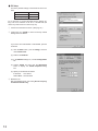
If your browser is Netscape Navigator, proceed as follows:
(1) Click the Edit menu, and then click Preferences.
(2) In the Preferences dialog box, click Advanced,
and then click Proxies.
(3) Select the Manual proxy configuration option,
and then click the [View] button to display the
Manual Proxy Configuration dialog box.
(4) In the space [Do not use proxy servers for
domains beginning with:], specify 192.168.0.10.
r In the Location bar, specify http://192.168.0.10.
t The browser displays the MAIN PAGE of the WJNT104's home page. If there is a camera input, it also
displays the camera image.
y Click [button] on the home page and verify the functions of the WJ-NT104.
For details on home page operations see MAIN PAGE
on page 30.
14
■ WJ-NT104 Setup
First, it is necessary to set an IP address for the WJ-NT104 according to the operating environment. Consult your network
administrator for the address to set.
● IP Address Setting via LAN Connection
q On the Location bar, enter http://192.168.0.10/hwsetup.html to display the ADMINISTRATOR SETUP
PAGE.
To open the ADMINISTRATOR SETUP PAGE, you
need to enter your user ID and password. The default
ID and password are [admin] and [nil], respectively.
Click the [NETWORK] button to display the NETWORK
SETUP dialog box.
w Set IP-ADDRESS, NETMASK, DEFAULT GATEWAY.
Consult your network administrator for the correct settings.
e Specify the TCP/IP settings for the PC.
If the PC is already operating on a network, specify its
original IP address in the TCP/IP Properties dialog box
(before changing it to 192.168.0.9).
● IP Address Setting via RS-232C
Connection
For further information, refer to page 54.
15
If the PC is running Windows95 or Windows98, select
Control Panel / Network / Configuration, click the
[Properties] button to open the TCP/ IP Properties
dialog box, and enter the IP address. Refer to the settings on page 13.
r Restart the PC.
t Start the PC’s browser.
Specify http://(IP address set in the WJ-NT104)/ in the
Location bar. The connection is established when the
image from the WJ-NT104 is displayed on the PC
screen.
Note: Refer page 14 for further details.
■ PPP Type Connection 1 (P to P ACCESS)
To use this mode, match the IP address of the PC with the address of the WJ-NT104.
The WJ-NT104 permits PPP (Point-to-Point Protocol) connection via a public line or the ISDN by connecting it to a modem
or a terminal adapter (TA).
RS-232C
cable
RS-232C
cable
Camera (max. 4)
Modem/TA
Modem/TA
WJ-NT104
Public lines
PC
(Windows 95 etc.)
● Setup Procedures
To set up the PPP connection, access the WJ-NT104 from a PC via a LAN and open the ADMINISTRATOR SETUP PAGE.
If the WJ-NT104 is already connected to a LAN, go to the Location bar and specify http://192.168.0.10 (or IP address set previously)/hwsetup.html to display the ADMINISTRATOR SETUP PAGE. If it is not yet connected to a LAN, connect to the LAN
following the procedures described under "PREPARATIONS" (p. 12) and specify hwsetup.html to open the ADMINISTRATOR
SETUP PAGE.
q On the ADMINISTRATOR SETUP PAGE, click the
[SERIAL PORT] button to open the SERIAL PORT
SETUP dialog box.
RS-232C SETUP
TYPE: Select MODEM/TA
BAUD RATE, DATA BIT, STOP BIT, PARITY, USE
FLOW CONTROL:
Set these items to match the settings of the
modem/TA used. If the settings of the modem/
TA are unknown, set 57 600 bps (see note), 8
bit, 1 bit, NONE, and NONE, respectively.
16
Note: Set a baud rate (net nec.) close to that of the
modem or TA connected. If there is a large difference, it may take much longer for images to
appear.
w Click the [SET&REBOOT] button to save the settings.
e On the ADMINISTRATOR SETUP PAGE, click the [MODEM] button to open the MODEM/TA SETUP dialog box.
Make the necessary entries for MODEM MODELS, MODEM INITIALIZE COMMAND (specify directly), LINE TYPE,
LOCAL TELEPHONE NUMBER, DESTINATION TELEPHONE NUMBER, LOGON ID, LOGON PASSWORD and REDIAL
(NUMBER OF TIMES/INTERVAL).
r Click the [SET] button to save.
t On the ADMINISTRATOR SETUP PAGE, click the [NETWORK] button to open the NETWORK SETUP dialog box. For
NETWORK TYPE, mark PPP.
y Click the [SET & REBOOT] button to save.
The WJ-NT104 is switched from LAN connection mode to PPP connection mode.
u Connect the RS-232C port on the rear panel of the WJ-NT104 to the RS-232C port on the modem/TA with a RS-232C
cable, and access the WJ-NT104 from a client PC via the modem/TA.
17
● Access Procedures
Follow these procedures to access the WJ-NT104 from a PC running Windows95 or Windows98 via a PPP type connection.
1. Preparations
q Check that the following software is installed in the PC.
• TCP/IP protocol
The TCP/IP protocol comes as an accessory with Windows95/98. Access the Control Panel → Network dialog box.
If TCP/IP → Dial-Up Adapter is not listed, you need to install the TCP/IP protocol.
For details refer to the Windows95/98 help file.
• Dial-Up Networking
Dial-Up Networking comes as an accessory with Windows95/98. If the Dial-Up Networking icon is not in My
Computer, it is not installed. To find out how to install it, refer to the Windows95/98 help file.
w Check the destination.
Check the phone number, phone system (type of line), communication speed, etc. of the client that will access the WJNT104.
e Connect a modem or TA to the PC and set it up.
The following description is based on the assumption that the device to which the modem or TA will be connected has
already been set up. For the modem or TA connection, refer to the instruction manual for the modem or TA.
2. Connection Setup
To access the WJ-NT104, set up the connection using Dial-Up Networking. It needs to be set up only once.
If the Dial-Up Networking icon is not in My Computer, it is not installed. You can use the following procedure to install it.
(1)
(2)
(3)
(4)
Click the Start button, point to Settings, and then click Control Panel.
Double-click Add/Remove Programs.
Click the Windows Setup tab, click Communications, and then click the [Details] button.
Click the Dial-Up Networking check box, and then click the [OK] button.
Click OK again, and follow the instructions on your screen.
q Double-click My Computer, and then double-click Dial-Up Networking.
18
w Double-click the Make New Connection icon.
e Type a name for the PC and select a modem. Then click the [Next] button.
r Enter the phone number and click the [Next>] button.
A message appears, reading [You have successfully created a new Dial-Up Networking connection called:].
t Click the [Finish] button.
The screen returns to the Dial-Up Networking window.
The newly created icon is displayed.
y Right-click the new icon to display the pull-down menu, and then click Properties.
19
y Click the [Server Type...] button.
u For Type of Dial-up Server, select PPP: Windows95, Windows NT 3.5, Internet (for Windows95), or PPP:
Windows95/98, Windows NT 4.0, Internet (for Windows98).
i Remove all checks in the Advanced options field.
o Check TCP/IP in the Allowed network protocols field.
!0 Click the [TCP/IP Settings....] button to display the TCP/IP Settings dialog box.
!1 Check Server assigned IP address.
!2 Check Server assigned name server addresses.
!3 Remove checks from User IP header compression and Use default gateway on remote network.
!4 Click the [OK] button.
The screen returns to the Server Types dialog box. Click the [OK] button and click it again.
20
3. Access Procedures
q Double-click the new icon in the Dial-Up Networking window.
w After checking the contents of the dialog box, click the [Connect] button.
The Connection Established dialog box is displayed after a short delay to indicate that the connection is under way.
* With some versions of Windows95 this dialog box is not displayed.
e Double-click the icon shown on the task bar to display the Connected to WJ-NT104 dialog box which indicates that the
connection is under way.
r To disconnect, click the [Disconnect] button.
21
■ PPP Type Connection 2 (NETWORK ACCESS)
1. Windows NT Setup
RS-232C
cable
RS-232C
cable
Camera (max. 4)
WJ-NT104
Modem/TA
CSU/DSU
Modem/TA
CSU/DSU
LAN
Dial-up server/
router etc.
Public lines
PC
(Windows95 etc.)
If the Dial-Up Networking icon is not in My Computer, it is not installed. You can use the following procedure to install it.
(1) Right-click the Network Neighborhood icon on the desktop, and then click Properties in the pull-down menu.
(2) In Network dialog box, click the Services tab.
(3) If the Remote Access Service is not in the Network Services list, click the [Add] button to display the Select Network
Service dialog box.
(4) Choose Remote Access Service, and then click the [OK] button to display the Windows NT Setup dialog box.
(5) Click the [Continue] button in the dialog box to install Remote Access Service.
q When installed, Remote Access Service appears in the
list of Network Services.
In the Network dialog box, choose Remote Access
Service, and then click the [Properties] button to display the Remote Access Setup window.
w Click the [Configure] button and configure the port in
the Configure Port Usage dialog box. Then click [OK]
to return to the Remote Access Setup window of Step
q.
e Click the [Network...] button and set the protocols
used in the Network Configuration dialog box as follows:
r Check TCP/IP in the Dial out Protocols field.
t Check TCP/IP in the Allow remote clients running
field.
y Check Allow any authentication including clear test
in the Encryption settings field.
22
u Click the [Configure...] button to display the RAS Server TCP/IP Configuration dialog box.
i Check Entire network in the Allow remote TCP/IP clients to access field.
o Check Use static address pool under Choose Cancel if you do not want to allow remote TCP/IP clients to dial in.
!0 Set Begin and End of an address.
The above dialog box setting applies in cases where addresses from 192.168.1.10 to 192.168.1.15 can be pooled.
Click the [OK] button.
!1 Set Remote Access Admin to grant remote access permission to users. To activate the Remote Access Admin.
(1) Click the Start button, point to Programs, and then Administrative Tools.
(2) Click Remote Access Admin.
(3) Point to Users menu and then click Permissions to display the Remote Access Permissions window.
!2 Select a user to whom remote access permission is to be granted, and check Grant dialin permission to user.
!3 Click the [OK] button.
23
2. Windows98 Setup
If the Dial-Up Networking icon is not in My Computer, it is not installed. You can use the following procedure to install it.
(1)
(2)
(3)
(4)
Click the Start button, point to Settings, and then click Control Panel.
Double-click Add/Remove Programs.
Click the Windows Setup tab, click Communications, and then click the [Details] button.
Click the Dial-Up Networking check box, and then click the [OK] button.
Click OK again, and follow the instructions on your screen.
q Click the icon on the taskbar to display the Dial-Up Server dialog box.
w If more than one modem is connected, click the tab at the top of the box and select a modem to use.
e Check Allow caller access.
r Click the [Change Password...] button.
The Dial-Up Networking Password dialog box is displayed.
t Enter a password, and then click the [OK] button
Type the same password as used to set up the connection and modem/TA.
y Click the [Server Types...] button to display the Server Types dialog box.
u For Types of Dial-Up Servers, select PPP:Internet, Windows NT Server, Windows98.
i In the Advanced options field, remove checks from Enable software compression and Require encrypted password.
o Click the [OK] button.
The screen returns to the Dial-Up Server dialog box. Click the [OK] button.
24
MAIN PAGE AND CONTROLS
■ Main Page and Control Windows
On the Location bar of the PC, type http://192.168.0.10 (or IP address set for WJ-NT104) to display the MAIN PAGE
default window.
The MAIN PAGE window is available in the following five modes:
1. Images without camera control / PULL mode
2. Images without camera control / PUSH mode
3. Images with camera control / PULL mode
4. Images with camera control / PUSH mode
5. Others
The mode 1 to 4 windows may differ slightly depending on the operation mode.
For the Main Page setup see MODE SETUP on page 41.
25
■ Operation Modes
The following three modes are available for controlling the input from the up to four cameras connected to the WJ-NT104.
¡Random Input Selection Mode
¡Multi Input Selection Mode
¡Fixed Input Selection Mode
To set up the mode, access the ADMINISTRATOR SETUP PAGE (see page 40) from the home page of the WJ-NT104.
To select a mode see MODE SETUP on page 41.
● Random Input Selection Mode
• Unless a user changes channels, the last selected channel is used to continue transmission.
A change of channel by one user causes the channels of the other users connected to the WJ-NT104 to be switched to
that same channel. This means that the monitored picture may suddenly change to another.
• The image transfer rate is highest in this mode.
• This mode is the factory default setting.
1
PC
CAMERA
1
CAMERA
PC
WJ-NT104
1
OPERATE
LINK RCV XMT
CAMERA
Network Interface Unit WJ-NT104
PC
1
CAMERA
PC
● Multi Input Selection Mode
• This mode switches periodically between multiple channels at high speed so that transmission to two or more users
requesting different channels is possible. There is no sudden change to another camera picture.
• The image transfer rate is lowest in this mode.
1
PC
CAMERA
2
CAMERA
PC
WJ-NT104
3
OPERATE
LINK RCV XMT
CAMERA
Network Interface Unit WJ-NT104
PC
4
CAMERA
PC
26
● Fixed Input Selection Mode
• You cannot select other than the channels specified by ADMINISTRATION SETUP PAGE.
• The image transfer rate is highest in this mode.
1
PC
1
CAMERA
PC
WJ-NT104
1
OPERATE
LINK RCV XMT
Network Interface Unit WJ-NT104
PC
1
PC
● Sequence Mode
• This is an applied version of Random Input Selection Mode, used to change channels at specified intervals.
Pan/tilt, zoom, and other camera functions cannot be controlled in this mode.
Channel Selection
1
PC
CAMERA
1
CAMERA
PC
WJ-NT104
1
OPERATE
LINK RCV XMT
CAMERA
Network Interface Unit WJ-NT104
PC
1
CAMERA
PC
27
■ Pull Mode and Push Mode
The WJ-NT104 has two modes of video output.
● Pull Mode
A request to receive the newest image is automatically and repeatedly sent from the PC to the WJ-NT104. The image
received by the PC is displayed as frame feed image (semi-animated picture). The process of sending the request, receiving the data, and displaying the image on the screen is performed by the Java Script program included in the HTML.
Camera (max. 4)
PC (browser)
Coaxial cable
(video + control)
Network
WJ-NT104
Request to receive the newest
image is sent from personal computer.
Note:To display images in pull mode requires Internet Explorer 4.0, Netscape Navigator 3.0, or a browser of a newer version
which can execute Java Script.
● Push Mode
A request to send continuous images is sent from the PC to the WJ-NT104. The WJ-NT104 receives the newest image at
set time intervals, and continuously sends the received images to the PC.
Camera (max. 4)
Coaxial cable
(video + control)
Network
WJ-NT104
Newest image is continuously
sent from the WJ-NT104.
PC (browser)
Note:To display images in push mode requires Netscape Navigator 3.X or a browser of a newer version. Internet Explorer
does not support displaying images in push mode.
To select a mode see MODE SETUP on page 41.
28
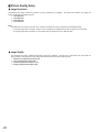
■ Picture Quality Setup
● Image Resolution
The following four image resolutions (number of picture elements) are available. The higher the resolution, the larger the
image and the lower the display speed.
q 752 x 568 pixel
w 752 x 280 pixel
e 368 x 280 pixel
r 176 x 136 pixel
Note:
The display size of images received in any of the above resolutions can be changed from the WWW browser.
• Incoming images with a resolution except of 752 x 280 pixels are displayed in the size in which they are received.
• Incoming images with a resolution of 752 x 280 pixels are displayed in 752 x 568 pixel size.
● Image Quality
The following four image qualities (compression ratios) are available. The lower the compression ratio, the better the
image quality, but the large size of the image data file slows down the image display speed.
q Super Fine (compressed to about 1/6)
w Fine (compressed to about 1/10)
e Normal (compressed to about 1/16)
r Rough (compressed to about 1/25)
29
■ MAIN PAGE (without Camera Control) [index1.html]
● Random Input Selection Mode
w
q
q INPUT SELECT
These buttons are used to switch the images of up to four cameras.
A change of channel by one user causes the channels of the other users connected to the WJ-NT104 to be switched to
that same channel.
w Live image display
Images of the selected camera are displayed on the default page as semi-animated pictures.
● Fixed Input Selection Mode
q
q Live image display
Only the images of the camera channels specified in the MODE SETUP window are displayed.
Note: Ordinary users are barred from selecting video input channels.
30
● Multi Input Selection Mode
e
q
w
q INPUT SELECT
These buttons are used to switch the images of up to four cameras.
A change of channel by one user affects only that terminal, but not the channels monitored by other users.
w QUAD SCREEN MODE
Clocking this button will display images of up to four cameras in quad pattern on a single monitor screen (see below).
e Live image display
Images of the selected camera are displayed on the default page as semi-animated pictures.
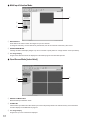
● Quad Screen Mode [index4.html]
q
w
e
q RETURN TO MAIN PAGE
Restores Multi Input Selection mode.
w ALARM LIST
Camera video input before and after alarm input can be temporarily stored in the internal memory of the WJ-NT104.
For alarm display see ALARM LIST on page 37.
e Live image display
Images from up to four cameras are displayed.
31
■ MAIN PAGE (with Camera Control) [index2.html]
● Random Input Selection Mode
r
t
y
q
u
i
w
o
e
!0
q INPUT SELECT
These buttons are used to switch images of up to four
cameras.
w PRESET SELECT
To move the combination camera (option) connected to
the WJ-NT104 to any of 8 preset position numbers.
To register preset positions refer to the CAMERA
MENU SETUP on page 53.
e ALARM LIST
Camera video input before and after alarm input can
be temporarily stored in the internal memory of the WJNT104.
For alarm display see ALARM LIST on page 37.
r Live image display
Images from the cameras connected to the WJ-NT104
are displayed.
Images of the selected camera are displayed on the
default page as semi-animated pictures.
t Pan/Tilt
Clicking anywhere on the live image moves the connected combination camera (option) up and down, or
to the right and left.
The camera pan/tilt angle
decreases as the point clicked moves closer to the
image center. Clicking the image center will not move
the camera. Zooming does not change the camera
pan/tilt angle. Click the image repeatedly to move the
camera to the desired position. You cannot pan or tilt
the camera continuously by dragging on the live
image.
32
y ZOOM
The connected combination camera (option) can be
zoomed by clicking the [TELE] or [WIDE] button under
ZOOM.
Clicking the [TELE] or [WIDE] button will operate the
camera in telescopic or wide-angle mode for a specified time, after which the mode is released automatically. These modes cannot be retained by keeping the
[TELE] or [WIDE] button depressed. You need to click
the [TELE] or [WIDE] button again.
u FOCUS
The connected combination camera (option) can be
focused by clicking the [FAR], [NEAR] or [AUTO] button under FOCUS.
Clicking the [FAR] or [NEAR] button will operate the
camera in focusing mode for a specified time, after
which the mode is released automatically. Clicking the
[AUTO] button will automatically focus the image on
the screen. Focus control cannot be retained by keeping the [FAR] or [NEAR] button depressed. You need
to click the [FAR] or [NEAR] button again.
i IRIS
The connected combination camera (option) can be
controlled to close or open the iris by clicking the
[OPEN] or [CLOSE] button under IRIS. Clicking the
[OPEN] or [CLOSE] button will open or close the camera iris for a specified time, after which the operation is
released automatically.
Clicking the [RESET] button on the screen will reset
the iris of the displayed camera to the factory default
setting. Iris control cannot be retained by keeping the
[OPEN] or [CLOSE] button depressed. You need to
click the [OPEN] or [CLOSE] button again.
o AUTOPAN
The auto pan status of the connected combination
camera (option) can be changed by clicking the [ON]
or [OFF] button under AUTOPAN.
Note: When LOCAL is selected in the camera setup,
AUTOPAN automatically stops after 1 minute.
When REMOTE is selected in the camera setup,
AUTOPAN will not be released automatically.
!0 PRESET
To move the connected combination camera (option) to
any of 64 preset positions. Select a preset position
number, then press the [SET] button to move the camera to the position.
33
● Fixed Input Selection Mode
e
r
t
q
y
u
w
i
o
q PRESET SELECT
To move the combination camera (option) connected to
the WJ-NT104 to any of 8 preset position numbers.
To register preset positions refer to the CAMERA
MENU SETUP on page 53.
w ALARM LIST
Camera video input before and after alarm input can
be temporarily stored in the internal memory of the WJNT104.
For alarm display see ALARM LIST on page 37.
e Live image display
Images from the cameras connected to the WJ-NT104
are displayed.
Note: Other than the camera of the channel set cannot
be selected.
r Pan/Tilt
Clicking anywhere on the live image moves the connected combination camera (option) up and down, or
to the right and left.
The camera pan/tilt angle
decreases as the point clicked moves closer to the
image center. Clicking the image center will not move
the camera. Zooming does not change the camera
pan/tilt angle. Click the image repeatedly to move the
camera to the desired position. You cannot pan or tilt
the camera continuously by dragging on the live
image.
34
t ZOOM
The connected combination camera (option) can be
zoomed by clicking the [TELE] or [WIDE] button under
ZOOM.
Clicking the [TELE] or [WIDE] button will operate the
camera in telescopic or wide-angle mode for a specified time, after which the mode is released automatically. These modes cannot be retained by keeping the
[TELE] or [WIDE] button depressed. You need to click
the [TELE] or [WIDE] button again.
y FOCUS
The connected combination camera (option) can be
focused by clicking the [FAR], [NEAR] or [AUTO] button under FOCUS.
Clicking the [FAR] or [NEAR] button will operate the
camera in focusing mode for a specified time, after
which the mode is released automatically. Clicking the
[AUTO] button will automatically focus the video on the
screen. Focus control cannot be retained by keeping
the [FAR] or [NEAR] button depressed. You need to
click the [FAR] or [NEAR] button again.
u IRIS
The connected combination camera (option) can be
controlled to close or open the iris by clicking the
[OPEN] or [CLOSE] button under IRIS. Clicking the
[OPEN] or [CLOSE] button will open or close the camera iris for a specified time, after which the operation is
released automatically.
Clicking the [RESET] button on the screen will reset
the iris of the displayed camera to the factory default
setting. Iris control cannot be retained by keeping the
[OPEN] or [CLOSE] button depressed. You need to
click the [OPEN] or [CLOSE] button again.
i AUTOPAN
The auto pan status of the connected combination
camera (option) can be changed by clicking the [ON]
or [OFF] button under AUTOPAN.
Note: When LOCAL is selected in the camera setup,
AUTOPAN automatically stops after 1 minute.
When REMOTE is selected in the camera setup,
AUTOPAN will not be released automatically.
o PRESET
To move the connected combination camera (option) to
any of 64 preset positions. Select a preset position
number then press the [SET] button to move the camera to the position.
● Multi Input Selection Mode
t
y
u
q
i
o
w
!0
e
!1
r
q INPUT SELECT
These buttons are used to switch images from up to
four cameras.
A change of channel by one user affects only that terminal, but not the channels monitored by other users.
w PRESET SELECT
To move the combination camera (option) connected to
the WJ-NT104 to any of 8 preset position numbers.
To register preset positions refer to the CAMERA
MENU SETUP on page 53.
e QUAD SCREEN MODE
Clicking this button will display images of up to four
cameras in quad pattern on a single monitor screen.
r ALARM LIST
Camera video input before and after alarm input can
be temporarily stored in the internal memory of the WJNT104.
For alarm display see ALARM LIST on page 37.
35
t Live image display
Images of the selected camera are displayed on the
default page as semi-animated pictures.
y Pan/Tilt
Clicking anywhere on the live image moves the connected combination camera (option) up and down, or
to the right and left.
The camera pan/tilt angle
decreases as the point clicked moves closer to the
image center. Clicking the image center will not move
the camera. Zooming does not change the camera
pan/tilt angle. Click the image repeatedly to move the
camera to the desired position. You cannot pan or tilt
the camera continuously by dragging on the live
image.
u ZOOM
The connected combination camera (option) can be
zoomed by clicking the [TELE] or [WIDE] button under
ZOOM.
Clicking the [TELE] or [WIDE] button will operate the
camera in telescopic or wide-angle mode for a specified time, after which the mode is released automatically. These modes cannot be retained by keeping the
[TELE] or [WIDE] button depressed. You need to click
the [TELE] or [WIDE] button again.
i FOCUS
The connected combination camera (option) can be
focused by clicking the [FAR], [NEAR] or [AUTO] button under FOCUS.
Clicking the [FAR] or [NEAR] button will operate the
camera in focusing mode for a specified time, after
which the mode is released automatically. Clicking the
[AUTO] button will automatically focus the video on the
screen. Focus control cannot be retained by keeping
the [FAR] or [NEAR] button depressed. You need to
click the [FAR] or [NEAR] button again.
o IRIS
The connected combination camera (option) can be
controlled to close or open the iris by clicking the
[OPEN] or [CLOSE] button under IRIS. Clicking the
[OPEN] or [CLOSE] button will open or close the camera iris for a specified time, after which the operation is
released automatically.
Clicking the [RESET] button on the screen will reset
the iris of the displayed camera to the factory default
setting. Iris control cannot be retained by keeping the
[OPEN] or [CLOSE] button depressed. You need to
click the [OPEN] or [CLOSE] button again.
!0 AUTOPAN
The auto pan status of the connected combination
camera (option) can be changed by clicking the [ON]
or [OFF] button under AUTOPAN.
Note: When LOCAL is selected in the camera setup,
AUTOPAN automatically stops after 1 minute.
When REMOTE is selected in the camera setup,
AUTOPAN will not stop automatically.
!1 PRESET
To move the connected combination camera (option) to
any of 64 preset positions. Select a preset position
number, then press the [SET] button to move the camera to the position.
36
ALARM FUNCTION
■ ALARM LIST Window
On the Location bar, type http://192.168.0.10 (or IP address set for WJ-NT104)/almindex.html, or click the ALARM LIST
button on the MAIN PAGE to display the ALARM LIST window. The window displays a list of alarm input dates, times and
channels. To display recorded alarm images, click the icon on the list.
q
e
w
r
t
u
i
o
q RETURN TO MAIN PAGE
Click to return to the MAIN PAGE window.
t GO TO FIRST FRAME
To jump to the first of a series of alarm images
w ALARM LIST
Displays a list of alarm IDs, dates, times and channels
where alarm was generated. The list stores up to 100
alarms. An icon at the right end of the line indicates
that images have been recorded. Clicking the icon will
display the alarm images.
y FRAME AT ALARM EVENT
To jump to the first image after an alarm in CONTINUOUS RECORDING (BEFORE/AFTER ALARM) mode; to
jump to the first of alarm images in CONTINUOUS
RECORDING (AFTER ALARM) mode.
e Alarm image display
Alarm images are displayed in this space. The image
display size is specified in the MODE SETUP window.
(Images for which size 640 x 240 was selected, will be
fitted to the screen (640 x 480)).
r ALARM IMAGE CONTROL PANEL
For frame-by-frame display of alarm images in CONTINUOUS RECORDING mode. The control panel is not
displayed in SINGLE FRAME RECORDING mode.
37
y
u GO TO LAST FRAME
To jump to the last of a series of alarm images
i PREVIOUS FRAME
To move one frame backward.
o NEXT FRAME
To move one frame forward.
■ ALARM Recording
The WJ-NT104 records images before and after an alarm is activated and notifies the user of alarm input. Alarm images
can be recorded in the following three modes:
● Single Frame Recording Mode
When an alarm is received, the alarm image is captured and saved as a still image after the specified delay time.
• The delay time from receiving an alarm until capture of the alarm image can be specified in the range of 0 to 10 seconds in increments of 100 ms.
Set delay time
Alarm activated
Single Frame Recording
Time base
● Continuous Recording [after alarm] Mode
When an alarm is received, the specified number of alarm images are captured and saved after the specified delay time.
• The delay time from receiving an alarm until capture of the alarm image can be specified in the range of 0 to 10 seconds in increments of 100 ms.
• The number of images to save can be set to between 1 and 16 (resolution 752 x 568).
• A frame rate of 1/10, 1/5, 3/10, 1/2, 1, 2, 3, 5, or 10 can be selected.
• If another alarm is received while recording an alarm, the on-going alarm processing is suspended and the new alarm
image is recorded with priority over the preceding one.
Set delay time
Alarm activated
Continuous recording
Time base
● Continuous Recording [before/after alarm] Mode
Images before receiving an alarm are recorded at the preset frame rate and in the preset number of images. After an
alarm is activated, the specified number of images are continuously captured and saved.
• The total number of images to be saved before and after an alarm can be set to between 1 and 16 (resolution 752 x
568).
• A frame rate of 1/10, 1/5, 3/10, 1/2, 1, 2, 3, 5, or 10 can be selected. (Frame rate 10 is not available for recording
before an alarm event.)
• If another alarm is received while recording an alarm, the on-going alarm processing is suspended and the new alarm
image is recorded with priority over the preceding one.
Before continuous
recording
After continuous
recording
Alarm activated
Note: This mode is valid only in Fixed Input Selection
mode is selected.
Time base
Maximum number of recorded alarm images
Differs depending on resolution and picture quality.
Super Fine/Fine Normal/Rough
752 x 568
16mages
24 images
752 x 280
41 images
57 images
368 x 280
90 images
122 images
176 x 136
255 images
255 images
38
■ ALARM NOTICE
The WJ-NT104 can notify the user of an alarm event.
The notice is sent either by Panasonic original protocol,
e-mail (SMTP client) or a combination of both.
● E-Mail Notice
Mail is sent to the mail server using SMTP (Simple Mail
Transfer Protocol).
16 mail addresses can be specified.
• Mail contents include the URL to access the alarm
image, date and time (hours, minutes, seconds) of
the alarm, camera channel, and connection port
ID.
• If mail is not sent to the mail server before the set
timeout, the mail is automatically deleted.
• In case of continuous recording [after/before], mail
contents are as follows:
[Explanation]
NT104:
Host name set by network setup (8 characters
maximum). Default setting is WJ-NT104.
Date and time of alarm activation:
Based on the time of the internal clock of the
WJ-NT104.
Generating port:
Port number of the alarm input/output terminal
where an alarm is generated
Link to alarm image:
Alarm image URL. In continuous recording
mode, the URL of the first image. In the following cases, accessing the URL may not display
the alarm image.
q Alarm image is overwritten.
(For the number of alarm images recorded see
page 38.)
w Alarm log is overwritten.
(Up to 100 alarm logs can be recorded.)
e NT104 is restarted due to a change in settings.
r Power is switched back on or the reset button
is pressed.
Number of frames recorded:
Number of alarm images to be recorded.
None in case Single Frame Recording
mode.
[Example]
!!! ALARM NOTICE !!!
Source
: 133. 185. 10. 47 (NT104)
Port
: PI0 5ch
Date
: Jul/04/99
Link
: http://133. 185. 10. 47/ALM0001_00.JPG
<NUMBER OF FRAMES RECORDED>
Total
: 14
Before
: 4
After
: 10
39
■ Alarm Image Readout
Recorded alarm images can be read out by accessing
the alarm list (almindex.html) of the WJ-NT104.
SETUP PROCEDURES
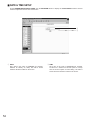
■ How to Read ADMINISTRATOR SETUP PAGE
On the Location bar, type http://192.168.0.10/hwsetup.html to display the ADMINISTRATOR SETUP PAGE. To open the
ADMINISTRATOR SETUP PAGE, you need to enter your user ID and password. The default ID and password are
[admin] and [nil (none)], respectively.
q
w
e
r
t
y
u
i
o
!0
!1
[SET][SUBMIT] button
Clicking this button stores the settings made on the
ADMINISTRATOR SETUP PAGE in the WJNT104.
The setting range of this button is indicated by the
ruled line that separates one item from another.
The area showing the data within the range returns
to the original display when the button is clicked.
The system is not restarted when this button is
pressed.
[SET & REBOOT] button
Clicking this button stores the settings made on
this page in the WJ-NT104. Remember, however,
that any recorded alarm data will be deleted.
q MODE SETUP
To set the default page when a file name is specified.
Also set operation mode, image quality, and camera
control selection on this page.
w NETWORK
To select LAN/PPP and set the IP address, network,
and default gateway.
e ALARM
To set alarm input ON/OFF, alarm image save mode,
image overwrite YES/NO, number of images recorded,
frame rate, and parallel I/O port (See page 37).
40
r SERIAL PORT
To select RS-232C or RS-485 and set the communication parameters.
t MODEM
To set the modem or TA to be used in the PPP connection.
y USER
User authorization, user registration, user deletion.
To register or delete a user table.
u HOST
To set the address of the host that can be accessed
without user certification.
i FTP CLIENT
To set the FTP client.
o DATE/TIME
To set the internal clock of the device.
!0 CAMERA MENU
To set connected cameras (option) by remote control.
!1 RETURN TO MAIN PAGE
To return to the MAIN PAGE window.
■ MODE SETUP
On the ADMINISTRATOR SETUP PAGE, click the MODE SETUP button to display the MODE SETUP window.
Select the operation mode, image quality and camera control.
q
e
r
t
y
q VIDEO INPUT SELECTION MODE
Select an operation mode for the camera displayed on
the monitor.
The factory default setting is RANDOM INPUT SELECTION MODE.
w INPUT CHANNEL
This item is available in FIXED INPUT SELECTION
MODE only. Select a channel for display on the monitor.
The factory default setting is CH1
e VIDEO INPUT CHANNEL ON/OFF
This item is available in RANDOM INPUT SELECTION
MODE or MULTI INPUT SELECTION MODE only.
• RANDOM INPUT SELECTION MODE
Channels set to OFF will not be displayed. In
sequence mode, such channels are skipped.
• MULTI INPUT SELECTION MODE
If a channel set to OFF is selected, the frame rate
goes up because images are captured by skipping
the channel set to OFF.
The factory default setting for channels are ON.
41
r INPUT CHANNEL SEQUENCE
This item is available in RANDOM INPUT SELECTION
MODE only.
Set sequence operation to ON or OFF.
The factory default setting is OFF.
t SEQUENCE INTERVAL
This item is available in RANDOM INPUT SELECTION
MODE only. It defines the dwell time (time until
changeover to the next channels) for sequence operation.
Dwell time can be set to a value between 1 and 30 seconds in increments of 1 second.
The factory default setting is 2 Sec.
y MAIN PAGE DEFAULT INDEX FILE SELECT
Set the window to be displayed when only a URL is
specified on the LOCATION bar.
Note: If OTHERS is marked, the name specified next to
File name will open the MAIN PAGE window.
The factory default setting is index1.html
u
i
o
!0
!1
!2
u RESOLUTION
Set a pixel number (resolution) for images from the WJNT104. The same value is applied for live images and
alarm images.
The factory default setting is 320x240 pixels
i IMAGE QUALITY
Set the image quality for images from the WJ-NT104.
The same value is applied for live images and alarm
images.
The factory default setting is FINE.
o FRAME SPEED CONTROL FOR PULL MODE
Set a frame speed for PULL mode.
1 is the highest frame speed. The higher the number,
the lower the frame speed.
The factory default setting is 3.
42
!0 FRAME SPEED CONTROL FOR PUSH MODE
Set a frame speed for PUSH mode.
This mode is supported by the Netscape Navigator
browser only.
1 is the highest frame speed. The higher the number,
the lower the frame speed.
The factory default setting is 3.
!1 OUTPUT DATA RATE CONTROL
Selecting a lower data rate reduces the possibility if a
network traffic jam.
The factory default setting is MAX.
!2 CAMERA CONTROL SELECT
A camera control cable can be selected for each channel.
The factory default setting is COAXIAL.
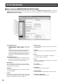
■ NETWORK SETUP
On the ADMINISTRATOR SETUP PAGE click the NETWORK button to display the NETWORK SETUP window.
Select LAN/PPP, and set IP address, netmask, and default gateway.
q
w
e
r
t
y
u
i
o
!0
q IP ADDRESS (LAN)
Enter the IP address to be used with LAN.
The factory default setting is 192.168.0.10.
w NETMASK (LAN)
Enter the netmask to be used with LAN.
The factory default setting is 255.255.255.0.
e DEFAULT GATEWAY (LAN)
Enter the default gateway to be used with LAN.
The factory default setting is 192.168.0.1.
r IP ADDRESS (PPP)
Enter the IP address to be used with PPP.
The factory default setting is 192.168.1.10.
t NETMASK (PPP)
Enter the netmask to be used with PPP.
The factory default setting is 255.255.255.0.
y DEFAULT GATEWAY (PPP)
Enter the default gateway to be used with PPP.
The factory default setting is 192.168.1.1.
u REMOTE IP ADDRESS
Used when PPP mode is on P to P ACCESS.
Enter the IP address of the PC which calls and accesses the WJ-NT104. The PC's IP address must be set to
Obtain an IP automatically. The factory default setting
is 192. 168. 1.11.
43
i PPP MODE
• P to P ACCESS mode
To use this mode, match the IP address of the PC
with the address of the WJ-NT104.
• NETWORK ACCESS mode
To use this mode, match the address of the WJNT104 with the address of the PC. (Independent of
outgoing and incoming calls)
The factory default setting is P to P ACCESS.
o HOSTNAME
Enter the host name.
Alarm notice (e-mail) is sent in the host name specified
here. The host name you enter may be different from
that entered for the domain settings (DNS).
The factory default setting is WJ-NT104.
!0 NETWORK TYPE
Select LAN or PPP.
If PPP is marked, access via LAN is not possible.
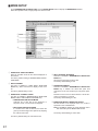
■ ALARM SETUP
On the ADMINISTRATOR SETUP PAGE, click the ALARM button to display the ALARM SETUP window.
q
w
e
r
t
y
u
q ALARM RECORDING/LOG
Set the alarm recording function to ON or OFF.
w ALARM RECORDING MODE
Select on alarm image recording mode.
e OVERWRITE
When YES is marked, old alarm images are overwritten
by new alarm images.
When NO is marked, new alarm images received after
the limit for recording of alarm images has been
reached will not be recorded.
r NUMBER OF RECORDING FRAMES
Set a number of images to be recorded before and
after an alarm is activated.
Note: Depending on the recording mode, this item is
not shown on the window.
44
t FRAME RATE OF RECORDING FRAME
Set a frame rate range for recording before and after
an alarm is activated.
Note: Depending on the recording mode, this item is
not shown on the window.
y ALARM CLEAR
Clicking this button clears the alarm images and alarm
log file saved in the memory.
u PARALLEL I/O PORT
Designate the Alarm Input/Output Port (Parallel I/O
port). The factory default setting is INPUT.
Port number 8 can also be used for time adjustment. If
a contact input is received within plus or minus 3 minutes of the hour, the internal clock is set to the hour.
!5
!6
!7
!8
!9
@0
@1
@2
i
o
!0
!1
!2
!3
!4
@3
@4
i PORT No.
Same as the alarm terminal numbers on the rear panel
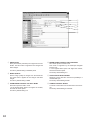
!5 ALARM NOTICE (SMTP E-MAIL)
To use the e-mail notice function, select YES.
o ALARM FUNCTION
Set the alarm function to ON or OFF.
!6 SERVER ADDRESS
Specify the address of the mail server to which mail is
sent directly from the WJ-NT104.
!0 CAMERA CH
Specify a camera channel to be selected when an
alarm is activated.
!1 CAMERA PRESET
Specify a preset position for the camera when an alarm
is activated.
This is valid only when a camera with preset function is
connected.
!7 SENDER NAME
Set the name of a mail sender (up to 8, alphanumeric
characters lower case).
!8 Destination E-Mail address
Specify the destination mail addresses of alarm notice
recipients. Up to 16 addresses can be set.
!2 DELAY TIME (per 100 msec)
Set the time from activation of an alarm to the start of
recording.
!9 Delete destination E-Mail addresses
Displays the list of e-mail addresses to receive alarm
notices. Clicking the DELETE button will delete an
address from the list.
!3 ALARM CONTACT
Select between normally closed (NC) and normally
open (NO) alarm contact.
open:
Accepts an NC alarm signal
close:
Accepts an NO alarm signal
@0 ALARM NOTICE (Panasonic Protocol)
If Panasonic's special alarm receiving software* is
installed, mark YES to use the alarm notice function.
* This software will be available in the near future as an
option.
!4 SET button
Clicking this button saves the settings in the WJ-NT104.
@1 DESTINATION PORT
Specify 1818.
@2 RETRY NUMBER OF TIMES
Enter the number of retries in the event that an alarm
notice is undeliverable.
@3 Destination IP address
Specify the IP addresses of PCs to which an alarm
notice is to be sent. Up to 16 IP addresses can be set.
@4 Delete destination IP addresses
Displays the list of IP addresses to receive alarm
notices. Clicking the DELETE button will delete an
address from the list.
45
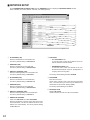
■ SERIAL PORT SETUP
On the ADMINISTRATOR SETUP PAGE, click the SERIAL PORT button to display the SERIAL PORT SETUP window.
Specify whether to use the RS-232C or RS-485 interface, and set the communication parameters.
q
w
e
r
t
y
u
i
o
!0
!1
!2
!3
q TYPE (RS-232C)
Set up the RS-232C port usage. Select NONE,
MODEM/TA, WJ-SX550A/B, WJ-FS616, WJ-DR200 or
Serial Through.
The factory default setting is NONE.
w BAUD RATE (RS-232C)
Set the baud rate for RS-232C to 300, 1200, 2400,
4800, 9600, 14400, 19200, 38400, 57600, or 115200
bps can be selected.
The factory default setting is 4800 bps.
It is recommended that 38400 bps be selected for a 56
kbps modem, and 57600 bps when for a TA.
i BAUD RATE (RS-485)
Set the baud rate for RS-485 to 1200, 2400, 4800,
9600, 19200, or 38400 bps can be selected.
The factory default setting is 4800 bps.
o DATA BIT (RS-485)
Set the data bits for RS-485.
The factory default setting is 8 bits.
e DATA BIT (RS-232C)
Set the data bits for RS-232C.
The factory default setting is 8 bits.
!0 STOP BIT (RS-485)
Set the stop bit for RS-485.
The factory default setting is 1 bit.
r STOP BIT (RS-232C)
Set the stop bit for RS-232C.
The factory default setting is 1 bit.
!1 PARITY(RS-485)
Set the parity bit for RS-485.
The factory default setting is NONE.
t PARITY (RS-232C)
Set the parity bit for RS-232C.
The factory default setting is NONE.
!2 X ON/X OFF (RS-485)
Set flow control for RS-485 (X ON/X OFF).
The factory default setting is OFF.
y USE FLOW CONTROL (RS-232C)
Set flow control for RS-232C.
The factory default setting is NONE.
46
u TYPE (RS-485)
Set up the RS-485 port usage. Select NONE or CAMERA + WJ-SX550A/B.
The factory default setting is NONE.
!3 DUPLEX MODE
Set the communication mode for RS-485.
The factory default setting is FULL DUPLEX.
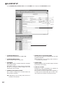
■ MODEM SETUP
On the ADMINISTRATOR SETUP PAGE, click the MODEM button to display the MODEM/TA SETUP window. Select the
modem or TA (terminal adapter) for the PPP connection.
q
w
e
r
t
y
u
i
o
q MODEM MODELS
Set a modem mode. Depending on the set value, the
modem initializing command is issued. Select manual
setting or standard modem.
The factory default setting is MANUAL SETTING.
w MODEM INITIALIZE COMMAND
This command is valid when MANUAL SETTING is
selected for MODEM MODELS.
Refer to the manual for the modem and set the initializing command.
e LINE TYPE
Select the type of telephone line to use. The factory
default setting is TONE.
r LOCAL TELEPHONE NUMBER
Set a telephone number for the WJ-NT104.
t DESTINATION TELEPHONE NUMBER
Set the destination telephone numbers in case the
alarm notice function is used.
y LOGON ID
Set an ID code to log into the destination network when
making calls from the WJ-NT104.
47
u LOGON PASSWORD
Set a password to log into the destination network
when making calls from the WJ-NT104.
i REDIAL (NUMBER OF TIMES/INTERVAL)
In case of failure of the PPP connection, the number is
redialed for the set number of times.
The factory default setting is 2 retries at intervals of 60
seconds.
o CONNECTION TIME (After alarm notice)
Set a time to automatically disconnect the line after the
WJ-NT104 accesses an alarm notice recipient. The
time countdown starts with completion of alarm notice
processing. The factory default setting is 0 minute.
■ USER SETUP
On the ADMINISTRATOR SETUP PAGE, click the USER button to display the USER SETUP window. Use this window to
register or delete users.
q
w
e
q USER AUTHORIZATION
Set USER AUTHORIZATION to OFF or ON.
Even if USER AUTHORIZATION is set to OFF, host
authorization is necessary to access the pages exclusive to your network administrator, or to use the FTP
function and PPP connection (to call the WJ-NT104).
The factory default setting is OFF.
w USER REGISTRATION
Set USER NAME, PASSWORD, and ACCESS LEVEL.
USER NAME and PASSWORD can be entered in up
to 16 upper or lower case alphanumerics characters
and symbols. Select an ACCESS LEVEL 1 to 4. To
change an already registered password and access
level, set them in the same way as to register a new
password and access level, and then press the [SUBMIT] button.
For user authorization, refer to the ACCESS AUTHORIZATION on page 57.
48
e DELETE USER
Select a registered user and click the [DELETE] button
to delete.
The list of currently registered users can be viewed by
clicking this pulldown list. The number in brackets is
the access level.
■ HOST SETUP
On the ADMINISTRATOR SETUP PAGE, click the HOST button to display the HOST SETUP window. Use this window to
register or delete hosts that can be accessed without user authorization.
q
w
e
q HOST AUTHORIZATION
Set HOST AUTHORIZATION to OFF or ON.
The factory default setting is OFF.
w HOST REGISTRATION
Set a HOST IP ADDRESS and ACCESS LEVEL.
Select an ACCESS LEVEL (1 to 4). To change an
already registered password and access level, set
them in the same way as to register a new password
and access level, and then press the [SUBMIT] button.
For host authorization, refer to ACCESS AUTHORIZATION on page 57.
49
e DELETE HOST
Select a registered HOST and press the [DELETE]
button to delete.
The list of currently registered hosts can be viewed by
clicking this pulldown list. The number in brackets is
the access level.
■ FTP CLIENT SETUP
On the ADMINISTRATOR SETUP PAGE, click the FTP CLIENT button to display the FTP CLIENT SETUP window.
Set FTP server address, user name, password, mode, Normal setup and Alarm setup.
q
w
e
r
t
y
!0
!1
u
!2
i
o
Common Setup
Normal Setup
q FTP SERVER ADDRESS
Specifies the IP address of the FTP server to which
images are sent directly from the WJ-NT104.
t FTP ON/OFF
Selects to enable or disable image upload with the FTP
periodically.
ON: Enables upload.
OFF: Disables upload.
w USER NAME
Specifies the user name when the WJ-NT104 logs in to
FTP server.
e PASSWORD
Specifies the password when the WJ-NT104 logs in to
FTP server.
y TARGET DIRECTORY
Specifies the absolute path for the directory of the FTP
server when uploading the images periodically.
r MODE
Specifies upload mode for FTP client.
u FTP EVENT SETUP IMAGE FILE NAME
Enter the desired image file name in the box.
The file name consists of x(image file name) ✽✽✽✽✽✽.
jpg
SEQUENTIAL MODE: The images are uploaded to the
data port on default value.
PASSIVE MODE: The images are uploaded to specified data port from FTP server.
50
The factory default is OFF.
x: camera CH number (1 – 4)
FIXED mode: Only the image file name, no addition
✽✽✽✽✽✽.
DATE/TIME mode: added digits (month, date, hour,
minute, second, and last 2-digit year).
Added MMDDhhmmsssYY (for example,
0123134500 101 for January 23 13:45:00.1, 2001)
SEQUENTIAL NUMBER(MAX FIXED) mode: added
number 00001 to 65535 automatically.
SEQUENTIAL NUMBER(MAX VARIABLE) mode:
added number between 00001 to max.(your setting
number till 65535).
Is disabled to specify over 65535.
i TRANSFER INTERVAL
Specify the interval time for uploading the data periodically.
Valid Value: seconds: between 0.2 and 1 with 0.1
increment
between 1 and 3600 with 1
increment
minutes: between 1 and 1440
For examples: 1min and 30sec: set 90 sec.
2 hours:
set 120 min.
Notes:
• It is disabled to specify the time in combination
with the minutes and seconds.
• It may occur that uploading is disabled with the
specified duration through the line status.
o FTP CHANNEL SELECT
You can specify the input channel for uploading when
the multi input selection mode is set in the MODE
SETUP window.
ON: Enables uploading.
OFF: Disables uploading.
The factory defaults are OFF.
Alarm Setup
!0 FTP ON/OFF
Selects to enable or disable alarm image upload with
the FTP when an alarm is received.
ON: Enables alarm upload.
OFF: Disables alarm upload.
The factory default is ON.
!1 TARGET DIRECTORY
Specifies the absolute path for the directory of the FTP
server when uploading the alarm images.
Note: There are 3 alarm recording modes available,
Single Frame, Continuous (post-images), and
Continuous (pre and post-images) recording. It is
enabled to specify the directory of FTP server for
normal and alarm status, and store the uploading
images separately.
!2 ALARM IMAGE FILE NAME SETUP
Enter the desired image file name in the box.
The file name consists of x(image file name)✽✽✽✽✽✽.
jpg
x: camera CH number (1 – 4)
FIXED mode: Only the image file name, no addition
✽✽✽✽✽✽.
DATE/TIME mode: added digits (month, date, hour,
minute, second, and last 2-digit year).
Added MMDDhhmmsssYY (for example,
0123134500101 for January 23 13:45:00.1, 2001)
SEQUENTIAL NUMBER(MAX FIXED) mode: added
number 00001 to 65535 automatically.
SEQUENTIAL NUMBER(MAX VARIABLE) mode:
added number between 00001 to max.(your setting
number till 65535).
Is disabled to specify over 65535.
Note: This FTP client function can support the FTP
server such as Windows 2000, Windows NT, Free
BSD, Turbolinux, and Red Hat Linux.
51
■ DATE & TIME SETUP
On the ADMINISTRATOR SETUP PAGE, click the DATE/TIME button to display the CLOCK SETUP window. Use this
window to adjust the internal clock of the device.
q
w
q DATE
Set a date in the order of YY/MM/DD (for example,
99/01/23 for January 23, 1999). The date is shown
when this window is called on the screen.
52
w TIME
Set a time in the order of HH:MM:SS (for example,
12:03:45 for 3 minutes 45 seconds past 12 o’clock).
Use the 24-hour system for time setting. The date is
shown when this window is called on the screen.
■ CAMERA MENU SETUP
On the ADMINISTRATOR SETUP PAGE, click the CAMERA MENU button to display the CAMERA MENU SETUP window.
The CAMERA MENU SETUP function is available in RANDOM INPUT SELECTION MODE and FIXED INPUT SELECTION MODE, but not in MULTI INPUT SELECTION MODE.
The cameras (option) can be set by remote control from this page.
For the individual functions of the camera menu, refer to the operating instructions for the camera.
q
w
e
u
i
!0
r
t
y
o
q MENU ON/OFF
Select ON or OFF for CAMERA MENU.
w ESC
Escape from the currently selection and return to the
previous page of the CAMERA MENU.
e MOVE CURSOR - Left
To move the cursor to the left. Use to change settings
or adjust levels.
i ALL RESET
To reset all camera settings to the factory defaults,
clicking this button when the cursor is positioned on the
CAMERA RESET in the SPECIAL MENU.
r MOVE CURSOR - Up
To move the cursor up.
o RESET
To reset individual parameters to the factory defaults.
Clicking this button will enter the SPECIAL MENU when
the cursor is positioned on the SPECIAL in the menu.
t MOVE CURSOR - Down
To move the cursor down.
!0 CAMERA SELECT
To select any of the cameras connected.
y MOVE CURSOR - Right
To move the cursor to the right. Use to change settings
or adjust levels.
53
u SET
To execute the currently selected settings or to enter a
submenu of the CAMERA MENU.
● Confirmation of the set values
Turn OFF all Mode Setup switches inside the WJNT104 front panel, and then press the RESET button to
restart the unit. Restarting makes the addresses
entered take effect.
Perform a communication check by means of ping
commands as follows.
q Connect the WJ-NT104 to the PC (see page 10).
10Base-T
crossover cable
WJ-NT104
PC
w Click the [START] button on the PC, and then point to [Programs]. In the program menu, choose [MS-DOS Prompt], and
enter the following commands.
C: \Windows>ping 192.168.0.10 (if the WJ-NT104 address is 192.168.0.10)
• The address has been set properly if the WJ-NT104 responds as follows:
Pinging 192.168.0.10 With 32 bytes of data :
Reply from 192.168.0.10 : bytes = 32 time = 1ms TTL = 255
Reply from 192.168.0.10 : bytes = 32 time = 1ms TTL = 255
Reply from 192.168.0.10 : bytes = 32 time = 1ms TTL = 255
Reply from 192.168.0.10 : bytes = 32 time = 1ms TTL = 255
• If the request times out without a response from the WJ-NT104, the address may not have been set properly. Attempt to
set it again.
Pinging 192.168.0.10 With 32 bytes of data :
Request timed out.
Request timed out.
Request timed out
Request timed out.
• If the WJ-NT104 responds as below, the network setup of the PC may be wrong. Correct the setup (e.g., change the IP
address to 192.168.0.2 and the sub netmask to 255.255.255.0), and enter the ping command again.
Pinging 192.168.0.10 With 32 bytes of data :
Destination host unreachable.
Destination host unreachable.
Destination host unreachable.
Destination host unreachable.
54
UTILITY SOFTWARE
■ Network Setup
For the network setup, you need to set the IP address
using the Utility Software provided and connect the WJNT104 to a PC via the RS-232C port.
RS-232C cable
● Connection
The COM1 port of the RS-232C interface is used for
setting the IP address. Your PC should be IBM-PC
compatible, have Windows95, Windows98 or Windows
NT4.0 installed, and have an RS-232C port.
Before installing the Utility Software provided, read the
Readme.txt file on Utility Software disc.
q Connect the RS-232C port on the front of the WJ-NT104
and the RS-232C port of the PC with an RS-232C
cable.
w Set bits #7 and #9 of the MODE selector to ON position
(leave the others on OFF), and then press the RESET
button on the front of the WJ-NT104.
e Click the Start button, point to Programs and then WJNT104 Utilities, then click Network Configuration.
r To set the IP address: Enter the IP address into the [IP
ADDRESS] fields of the dialog box, then click the
[SET] button. If the IP address has been set properly,
the response command REI and the IP address entered (in hexadecimal, 8-bit notation, e.g., REI:COA8000A
for IP address 192.168.0.10) should appear in the WJNT104 RESPONSE field. If a wrong number is shown,
click the [SET] button again.
t To set the netmask: Enter a set value into the [NETMASK] fields of the dialog box, then click the [SET]
button. If the netmask has been set properly, the
response command REM and the set value entered (in
hexadecimal, 8-bit notation, e.g., REM:FFFFFF00 for
the set value 255.255.255.0) should appear in the WJNT104 RESPONSE field. If a wrong number is shown,
click the [SET] button again.
y To set the default gateway: Enter a set value into the
[DEFAULT GATEWAY] fields of the dialog box, then
click the [SET] button. If the default gateway has been
set properly, the response command REG and the set
value entered (in hexadecimal, 8-bit notation, e.g.,
REG:COA80001 for the set value 192.168.0.1) should
appear in the WJ-NT104 RESPONSE field. If a wrong
number is shown, click the [SET] button again.
u Complete the setup by clicking the [EXIT] button.
i Return all switches on the MODE selector to OFF position and then press the RESET button on the front of the
WJ-NT104.
This completes setup and return to the normal application mode.
55
WJ-NT104
PC
1
1
2
2
3
3
4
4
5
5
6
6
7
7
8
8
Frame
Frame
Shield
9-pin D-sub connector
(female)
9-pin D-sub connector
(female)
■ Camera Menu Setup
This is software to control the camera menu of the WV-CS654 and CS854 (optional).
It allows a user to open the menu of a camera connected to the WJ-NT104 with a coaxial cable and select preset position
and other camera settings.
Camera
RS-232C cable
WJ-NT104
PC (DOS/V)
● Operation
q Connect the RS-232C port on the front of the WJ-NT104 and the RS-232C port of the PC with an RS-232C cable.
w Set bits #7 and #9 of the MODE selector to ON position (leave the others on OFF), and then press the RESET button on the
front of the WJ-NT104.
e Click the Start button, point to Programs and then WJ-NT104 Utilities. Click Camera Setup.
r Select a channel under Camera Select.
t Click the [MENU ON/OFF] button, to open the Menu.
Should it not appear, click the button repeatedly.
y Use [UP], [DOWN], [LEFT], [RIGHT], [ENTER], and [ESC] buttons to select a menu and execute a selected menu item.
For menu operations and setup refer to the operation manual of the connected camera.
u The [SPECIAL] button is effective only when the cursor points to SPECIAL on the camera menu.
i When the [Camera Control] button is depressed, a panel for Coaxial Camera Control appears.
PAN/TILT, ZOOM, and FOCUS control are selectable only in the “position setting menu.”
o To exit from the setup, press the [EXIT] button.
!0 Return all switches on the MODE selector to OFF position and then press the RESET button on the front of the WJ-NT104.
This completes setup and return to the normal application mode.
56
ACCESS AUTHORIZATION
■ Control of Access
Authorization
User access authorization is controlled as follows.
● Unlimited access
If neither user nor host authorization is used (set to
OFF) in a network, all users may perform the following
operations at access level 2.
• Controlling cameras and other equipment connected to the WJ-NT104
• Monitoring live images
• Monitoring alarm images and querying the log files
• Accessing the data stored in the WJ-NT104
* Accessing the ADMINISTRATOR SETUP PAGE of the
WJ-NT104 requires an administrator account.
● Limited access
• Access is limited according to the host access levels
specified in the HOST SETUP window. The HOST
SETUP window is queried using the IP address of the
host requesting access to the WJ-NT104.
When
accessing via a proxy server, the access level therefore is determined by the IP address of the proxy server.
• When access is made from a PC not registered in the
HOST SETUP window, the dialog box shown below
prompts the user to enter User Name and Password.
The access level is determined when both the user
name and password are entered.
■ Access Level
Four access levels can be assigned to control access
by users.
More than one user can be assigned the same access
level. While device control commands are given top
priority in the execution chain, there is no priority
attached to the access level. It is possible to designate
more than one network administrator and to change
designated administrators.
● Administrator (Level 1)
• Access to and setup of ADMINISTRATOR SETUP
PAGE
• Rewriting data stored in the WJ-NT104 using FTP
(File Transfer protocol)
• Controlling cameras and other equipment connected to the WJ-NT104
• Monitoring live images
• Monitoring alarm images and querying the log files
• Accessing the data stored in the WJ-NT104
● Input Select and operation (Level 2)
• Controlling cameras and other equipment connected to the WJ-NT104
• Monitoring live images
• Monitoring alarm images and querying the log files
• Accessing the data stored in the WJ-NT104
● Monitoring only (Level 3)
• Monitoring live image.
• Monitoring alarm images and querying the log files
• Accessing the data stored in the WJ-NT104
● Unauthorized level (Level 4)
• Access to the WJ-NT104 is denied.
57
■ Registration
Administrator level (Level 1) users only can be registered in the HOST SETUP and USER SETUP windows. Each window is
provided with fields for making the necessary entries.
The factory default setting is USER NAME: admin, PASSWORD: nil (none), ACCESS LEVEL: 1. An "admin" user can
change passwords, but is not authorized to delete users or change access levels.
● Host Setup Window
● User Setup Window
A maximum of 16 terminal addresses can be registered
in the HOST SETUP window. Initially there are no
addresses registered.
Enter the host IP address as a dotted (.) notation, for
example. 192.168.0.10. The host name cannot be
specified. The host IP address "0.0.0.0" is invalid.
Select (mark) any of access levels 1 to 4.
A maximum of 16 users can be registered in the USER
SETUP window.
Enter a user name and password consisting of up to 16
alphanumeric characters (case sensitive).
Select
(mark) any of access levels 1 to 4.
● WJ-NT104 Authorized Functions
Operation
Request
Check
Operation Level
Host Level
Authorization Process
NG
OK
User Level
Authorization Process
OK
Operation will
be Accepted
58
NG
Operation will
be Denied
EXTENSION FUNCTIONS
■ WJ-FS616 Video Multiplexer Control
● Connection
(1) Connect MULTISCREEN OUT on the rear of the WJ-FS616 to VIDEO IN 1 on the rear of the WJ-NT104.
(2) Connect the RS-232C ports of both units with a RS-232C cable.
• Fixed Input Selection Mode
In this mode, only images from the MULTISCREEN OUT connector of the Video Multiplexer are available.
RS-232C
DB25
DB9
2 ......................... 2
3 ......................... 3
6 ......................... 4
7 ......................... 5
20 ....................... 6
5 ......................... 7
4 ......................... 8
WJ-FS616
(MULTISCREEN OUT)
1
PC
1
PC
WJ-NT104 (VIDEO IN1)
1
16
LOCK
ALARM
MULTI
SCREEN
MULTISCREEN
SELECT
RESET
SPOT
SEQUENCE
CAMERA/PRESET POSITION
1
POWER
ON
OFF
VCR
CAM
2
3
PUSH OPEN
4
OPERATE
5
6
7
8
9
10
11
12
13
14
15
16
LINK RCV XMT
Network Interface Unit WJ-NT104
PC
1
PC
● Setup
(1) On the ADMINISTRATOR SETUP PAGE, click the [SERIAL PORT] button to open the SERIAL PORT SETUP window.
For TYPE, select "WJ-FS616. Set the same communication parameters as for the WJ-FS616.
(2) On the ADMINISTRATOR SETUP PAGE, click the [MODE SETUP] button to open the MODE SETUP window.
(3) For VIDEO INPUT SELECTION MODE under OPERATION MODE SELECT, mark FIXED INPUT SELECTION MODE.
● Control Operation
On the Location bar, type http://192.168.0.10/fsindex.html to open the WJ-FS616 OPERATION VIEW window.
!3
q
w
e
r
59
o
y
!0
u t
!1
i
!2
q CAMERA SELECT (Left window panel)
To select a camera (camera 1 to 16) connected to the
WJ-FS616 Video Multiplexer. The image of the selected camera is displayed in spot mode.
w PRESET SELECT (Left window panel)
To move the combination camera (option) connected to
the WJ-FS616 to any of 8 preset positions.
e ALARM LIST
Any image before or after alarm input can be temporarily stored in the internal memory of the WJ-NT104. For
alarm display see ALARM LIST on page 37.
r CAMERA SELECT (Bottom window panel)
To select a camera (camera 1 to 16) connected to the
WJ-FS616. Select a camera number, and then click
[SET] to apply it. The image of the selected camera is
displayed in spot mode.
t MULTISCREEN SELECT
Clicking this button repeatedly will switch the screen as
follows:
4 → 7 → 9 → 10 → 13 → 16→ 4 screen segments
y PRESET SELECT (Bottom window panel)
To move the combination camera (option) connected to
the WJ-FS616 to any of 64 preset positions. Select a
preset position number, and then click the [SET] button
to move the camera to the position.
u ALARM ALL RESET
To reset all alarms activated in the Video Multiplexer,
and return it to normal condition.
i PAN/TILT
Clicking anywhere on the live image moves the connected combination camera (option) up and down, or
to the right and left.
The camera pan/tilt angle
decreases as the point clicked moves closer to the
image center. Clicking the image center will not move
the camera. Zooming does not change the camera
pan/tilt angle. Click the image repeatedly to move the
camera to the desired position. You cannot pan or tilt
the camera continuously by dragging on the live
image.
o ZOOM
The connected combination camera (option) can be
zoomed by clicking the [TELE] or [WIDE] button under
ZOOM.
Clicking the [TELE] or [WIDE] button will operate the
camera in telescopic or wide-angle mode for a specified time, after which the mode is released automatically. These modes cannot be retained by keeping the
[TELE] or [WIDE] button depressed. You need to click
the [TELE] or [WIDE] button again.
60
!0 FOCUS
The connected combination camera (option) can be
focused by clicking the [FAR], [NEAR] or [AUTO] button under FOCUS.
Clicking the [FAR] or [NEAR] button will operate the
camera in focusing mode for a specified time, after
which the mode is released automatically. Clicking the
[AUTO] button will automatically focus the image on
the screen. Focus control cannot be retained by keeping the [FAR] or [NEAR] button depressed. You need
to click the [FAR] or [NEAR] button again.
!1 IRIS
The connected combination camera (option) can be
controlled to close or open the iris by clicking the
[CLOSE] or [OPEN] button under IRIS.
Clicking the [OPEN] or [CLOSE] button will open or
close the camera iris for a specified time, after which
the operation is released automatically.
Clicking the [RESET] button on the screen will reset
the iris of the displayed camera to the factory default
setting. Iris control cannot be retained by keeping the
[OPEN] or [CLOSE] button depressed. You need to
click the [OPEN] or [CLOSE] button again.
!2 AUTO PAN
The auto pan status of the connected combination
camera (option) can be changed by clicking the [ON]
or [OFF] button under AUTOPAN.
Note: Note: When LOCAL is selected in the camera
setup menu, auto pan is released automatically
after 1 minute. When REMOTE is selected, auto
pan will not be released automatically.
!3 Image Display
The image output from the MULTISCREEN OUT connector of the video multiplexer connected to the WJNT104 is displayed.
■ WJ-SX550A/B/C Matrix Switcher Control
● Connections
(1) Connect the MONITOR OUT connectors on the rear of the WJ-SX550A/B/C to the VIDEO IN connectors 1 to 4 on the
rear of the WJ-NT104.
(2) Connect the RS-232C ports (of WJ-SX550A/B/C and WJ-NT104) with a RS-232C cable. You can also connect the
CONTROL DATA port on the rear of the WJ-SX550A/B/C to the RS-485 connectors on the rear of the WJ-NT104.
• Random Input Selection Mode
For VIDEO INPUT SELECTION MODE under OPERATION MODE SELECT, mark RANDOM INPUT SELECTION MODE.
Unless a user changes channels, the last selected channel is used to continue transmission.
The image transfer speed is higher than in Multi Input Selection Mode.
Data Port (WJ-SX550A/B/C)
Pin No.
Designation
1
Ground
2
R(B)
3
R(A)
4
T(B)
5
T(A)
6
Ground
WJ-SX550A/B/C
Monitor
Out 1
Monitor
Out 2
Monitor
Out 3
Monitor
Out 4
OPERATE
Matrix Switcher WJ-SX
RS-232C
DB25
DB9
8 ...................... 1
3 ...................... 2
2 ...................... 3
20 .................... 4
7 ...................... 5
6 ...................... 6
4 ...................... 7
5 ...................... 8
22 .................... 9
R(B)
R(A)
T(B)
T(A)
RS-485
............ T(B)
............ T(A)
............ R(B)
............ R(A)
1
PC
MON1
MON2
PC
MON1
MON2
PC
MON1
MON2
PC
MON1
MON2
1
WJ-NT104
1
OPERATE
LINK RCV XMT
Network Interface Unit WJ-NT104
550
1
• Multi Input Selection Mode
For VIDEO INPUT SELECTION MODE under OPERATION MODE SELECT, mark MULTI INPUT SELECTION MODE.
This mode switches periodically between multiple channels at high speed so that transmission to two or more users
requesting different channels is possible.
The image transfer speed is lower than in Random Input Selection Mode.
1
PC
MON1
PC
MON2
PC
MON3
PC
MON4
2
WJ-SX550A/B/C
Monitor
Out 1
Monitor
Out 2
Monitor
Out 3
Monitor
Out 4
OPERATE
Matrix Switcher WJ-SX
WJ-NT104
3
OPERATE
LINK RCV XMT
Network Interface Unit WJ-NT104
550
4
61
● Setup
In the SERIAL PORT SETUP window, set TYPE under RS-232C SETUP or RS-485 SETUP to "WJ-SX550A". Set the same
communication parameters as for the Matrix Switcher. (For further details refer to the operation manual of the WJ-SX550A
Matrix Switcher.) Click the link to [MATRIX SW CONFIGURATION page] at the bottom of the SERIAL PORT SETUP window to open the MATRIX SWITCHER CONFIGURATION window.
q
w
q PASSWORD
Enter the same 5-digit password as set for the Matrix
Switcher.
w VIDEO-INPUT NUMBER AND MONITOR-OUT CHANNEL SETUP
Set a channel number for the monitor output of the WJ-
WJ-SX550A Matrix Switcher to be connected to the
video input connector on the WJ-NT104 network interface unit. The status when selecting VIDEO-INPUT (at
WJ-NT104) in the above table is the same as when a
monitor compatible with the WJ-SX550A is selected.
● Control Operation
On the Location bar, type the URL http://192.168.0.10/sxindex.html to access the WJ-SX550 OPERATION VIEW window for
the Matrix Switcher.
!4
!5
q
w
y
u
i
e
o
r
t
62
!0
!1
!2
!3
q VIDEO IN (WJ-NT104)
Selects any of the four video inputs of the Interface Unit
for display on the monitor. Set the monitor outputs of
the Matrix Switcher to match the video inputs of the
Interface Unit, referring to MATRIX SWITCHER CONFIGURATION on page 62.
The video channels will be switched in accordance
with the operating mode selected. Refer to MAIN
PAGE AND CONTROLS on page 25 for a description of
operating modes and to MODE SETUP on page 41 for
mode setting procedures.
!1 FOCUS
The connected combination camera (option) can be
focused by clicking the [FAR], [NEAR] or [AUTO] button under FOCUS.
Clicking the [FAR] or [NEAR] button will operate the
camera in focusing mode for a specified time, after
which the mode is released automatically. Clicking the
[AUTO] button will automatically focus the image on
the screen. Focus control cannot be retained by keeping the [FAR] or [NEAR] button depressed. You need
to click the [FAR] or [NEAR] button again.
w CAMERA SELECT (Left window panel)
To select a camera (camera 01 to 08) connected to the
WJ-SX550A Matrix Switcher. The image of the selected
camera is displayed on the monitor in the previously
selected input mode.
!22 IRIS
The connected combination camera (option) can be
controlled to close or open iris by clicking the [CLOSE]
or [OPEN] button under IRIS.
Clicking the [OPEN] or [CLOSE] button will open or
close the camera iris for a specified time, after which
the operation is released automatically.
Clicking the [RESET] button on the screen will reset
the iris of the displayed camera to the factory default
setting. Iris control cannot be retained by keeping the
[OPEN] or [CLOSE] button depressed. You need to
click the [OPEN] or [CLOSE] button again.
e PRESET SELECT (Left part of screen)
To move the combination camera (option) connected to
the WJ-SX550A to any of 8 preset positions.
r ALARM LIST
Any image before and after alarm input can be temporarily stored in the internal memory of the WJ-NT104.
For alarm display see ALARM LIST on page 37.
t CAMERA SELECT (Bottom window panel)
To select a camera (CAMERA 1 to 128) connected to
the WJ-SX550A. Select a camera number, and then
click [SET] to apply it. The image of the selected camera is displayed on the monitor in the previously selected input mode.
y PRESET SELECT (Bottom window panel)
To move the combination camera (option) connected to
the WJ-SX550A to any of 64 preset positions. Select a
preset position number, and then click the [SET] button
to move the camera to the position.
u TOUR SEQUENCE
To run the tour sequence of the WJ-SX550 matrix
switcher. Select a tour sequence number, and then
click the [SET] button to run the sequence.
i PROGRAM SEQUENCE
To run the program sequence of the WJ-SX550 matrix
switcher. Click the [SET] button to run the assigned
sequence.
o ALARM ALL RESET
To reset all alarms activated in the Matrix Switcher, and
return it to normal condition.
!0 ZOOM
The connected combination camera (option) can be
zoomed by clicking the [TELE] or [WIDE] button under
ZOOM.
Clicking the [TELE] or [WIDE] button will operate the
camera in telescopic or wide-angle mode for a specified time, after which the mode is released automatically. These modes cannot be retained by keeping the
[TELE] or [WIDE] button depressed. You need to click
the [TELE] or [WIDE] button again.
63
!33 AUTO PAN
The auto pan status of the connected combination
camera (option) can be changed by clicking the [ON]
or [OFF] button under AUTOPAN.
Note: When LOCAL is selected in the camera setup
menu, auto pan is released automatically after 1
minute. When REMOTE is selected, auto pan will
not be released automatically.
!4 Image Display
To display the image output from the Matrix Switcher
connected to the WJ-NT104 Interface Unit. Set the
monitor outputs of the Matrix Switcher to match the
video inputs of the Interface Unit, referring to MATRIX
SWITCHER CONFIGURATION on page 62.
!5 PAN/TILT
Clicking anywhere on the live image moves the connected combination camera (option) up and down, or
to the right and left.
The camera pan/tilt angle
decreases as the point clicked moves closer to the
image center. Clicking the image center will not move
the camera. Zooming does not change the camera
pan/tilt angle. Click the image repeatedly to move the
camera to the desired position. You cannot pan or tilt
the camera continuously by dragging on the live
image.
■ WJ-DR200 AV Disk Recorder Control
● Connections
• Fixed Input Selection Mode
(1) Connect CAMERA 1 and 2 to the VIDEO IN A and B connectors on the rear of the WJ-DR200.
(2) Connect the VIDEO OUT connector on the rear of the WJ-DR200 to the VIDEO IN 1 connector on the rear of the WJNT104.
(3) Connect the RS-232C ports (of WJ-DR200 and
RS-232C
WJ-NT104) with a RS-232C cable.
DB25
DB9
• Only the images from the VIDEO OUT connector
2 ...................... 2
3 ...................... 3
on the rear of the AV Disc Recorder are availDR
6 ...................... 4
able.
7 ...................... 5
20 .................... 6
5 ...................... 7
4 ...................... 8
CAMERA 1
(VIDEO OUT)
WJ-DR200
REMOTE
ALARM
DISC
CONTROL
PUSH OPEN
PUSH OPEN
RESET
OPERATE
ALARM
REC
PC
DR
WJ-NT104 (VIDEO IN 1)
PC
OPERATE
LINK RCV XMT
RAM
REC
DISC
AV Disc Recorder WJ-DR
Network Interface Unit WJ-NT104
DR
CAMERA 2
PC
• Random Input Selection Mode
(1) Connect CAMERA 1 and 2 to the VIDEO IN 1 and 2 connectors on the rear of the WJ-NT104.
(2) Connect the VIDEO OUT 1 and 2 connectors on the rear of the WJ-NT104 to the VIDEO IN A and B connectors of the
WJ-DR200.
(3) Connect the VIDEO OUT connector of the WJ-DR200 to the VIDEO IN 3 connector of the WJ-NT104.
(4) Connect the RS-232C ports (of WJ-DR200 and WJ-NT104) with a RS-232C cable.
• For VIDEO INPUT SELECTION
CAM1
MODE under OPERATION MODE
SELECT, mark RANDOM INPUT
PC
CAMERA 1
SELECTION MODE.
CAM1
WJ-NT104
• Enables control of cameras connected to the VIDEO IN connector
PC
CAMERA 2
of the WJ-NT104 (requires cusCAM1
tomizing the WJ-DR200 OPERATION VIEW window).
(VIDEO OUT)
WJ-DR200
PC
• Unless a user changes channels,
the last selected channel is used to
continue transmission.
OPERATE
LINK RCV XMT
Network Interface Unit WJ-NT104
REMOTE
ALARM
DISC
CONTROL
PUSH OPEN
PUSH OPEN
RESET
OPERATE
RAM
ALARM
REC
REC
DISC
AV Disc Recorder WJ-DR
• Multi Input Selection Mode
(1) Connect CAMERA 1 and 2 to the VIDEO IN 1 and 2 connectors on the rear of the WJ-NT104.
(2) Connect the VIDEO OUT 1 and 2 connectors on the rear of the WJ-NT104 to the VIDEO IN A and B connectors of the
WJ-DR200.
(3) Connect the VIDEO OUT connector of the WJ-DR200 to the VIDEO IN 3 connector of the WJ-NT104.
(4) Connect the RS-232C ports (of WJ-DR200 and WJ-NT104) with a RS-232C cable.
• For VIDEO INPUT SELECTION MODE under OPERATION MODE SELECT, mark MULTI INPUT SELECTION MODE.
• Enables control of cameras connected to the VIDEO IN connector
CAM1
of the WJ-NT104 (requires customizing the WJ-DR200 OPERAPC
CAMERA 1
TION VIEW window).
CAM2
WJ-NT104
• This mode switches periodically
between multiple channels at high
PC
CAMERA 2
speed so that transmission to two or
DR200
more users requesting different
channels is possible.
PC
OPERATE
LINK RCV XMT
Network Interface Unit WJ-NT104
WJ-DR200
REMOTE
ALARM
DISC
CONTROL
PUSH OPEN
PUSH OPEN
RESET
OPERATE
ALARM
REC
RAM
REC
DISC
AV Disc Recorder WJ-DR
64
(VIDEO OUT)
● Setup
In the SERIAL PORT SETUP window, set TYPE under RS-232C to "WJ-DR200". Set the same communication parameters
as for the WJ-DR200 AV Disk Recorder. (For further details refer to the operation manual of the WJ-DR200 AV Disk
Recorder.)
● Control Operation
On the Location bar, type the URL http://192.168.0.10/drindex.html to access the WJ-DR200 OPERATION VIEW window
for the AV Disk Recorder.
!9
q
w
e
r
tyu
i
o !4 !0 !5 !1 !6 !2 !7 !3 !8
q ALARM REC STANDBY
To toggle between enabling and disabling alarm
recording on the WJ-DR200 AV Disk Recorder.
w INDEX
To search the disk for recorded frames. Clicking the
[INDEX] button opens the WJ-DR200 RECORD LIST
window. Click the [REFRESH] button in the window to
refresh the recording list displayed in the image window. Then click the recording number to play back the
selected frames. To exit from search mode, click the
[STOP] button.
65
This button also toggles between displaying recordings
as a list and as a group of thumbnails.
You can also use this window to search the disk by the
same operation as from the WJ-DR200.
Refer to the operation manual of the WJ-DR200 for
details.
e FIND
To directly specify and play back a recorded frame.
r UP/Next Frame
Click in paused playback to advance the playback
operation one step to the next frame.
Also moves the cursor up one line in the recording list
or thumbnails.
t LEFT/Prev Rec
To move the playback operation back one step to the
previous record.
Also moves the cursor to the left in the recording list or
thumbnails.
y SET
Click to start playback of frames selected in the recording list or group of thumbnails.
In frame search, click this button to apply the entered
value.
u RIGHT/Next Rec
To move the playback operation one step to the next
record.
Also moves the cursor to the right in the recording list
or thumbnails.
i DOWN/Prev Frame
Click in paused playback to move the playback operation back one step to the previous frame.
Also moves the cursor down one line in the recording
list or thumbnails.
o REW
To play back a recording in backward search.
!0 REVERSE PLAY
To play back frames in reverse order.
!1 STOP
Clicking this button will terminate all modes of operation, such as recording, playback, and setting.
!2 PLAY
To play back frames in forward order.
!3 FF
To play back a recording in forward search.
!4 REC
To start recording in the previously defined mode.
!5 PAUSE
Click to temporarily pause playback.
!6 TL MODE - (minus)
Clicking this button in playback will increase the playback speed.
Clicking it in paused playback will decrement the playback channel (or camera ID). To play back the selected channel, click the [PLAYBACK SELECT] button.
66
!7 TL MODE + (plus)
Clicking this button in playback will decrease the playback speed.
Clicking it in paused playback will increment the playback channel (or camera ID). To play back the selected channel, click the [PLAYBACK SELECT] button.
!8 PLAYBACK SELECT
Clicking this button after selecting the input channel
with the (+) or (–) button will start playback of the
respective channel.
!9 Image Display
To display the images previously selected as input.
Note: Note: The buttons in the window have the same functions as those of the WJ-DR200. Refer to the operation
manual of the WJ-DR200 for details.
■ WJ-HD100 Digital Disk Recorder Control
It is enabled control of the WJ-HD100 disk recorder from the PC via the WJ-NT104 Network Interface Unit. (disabled control
with PSoData)
Also refer to the operating instructions for the disk recorder together.
● Connections
• Fixed input selection mode
In this mode, only images from the MONITOR OUT connector of the disk recorder are available.
(1) Connect MONITOR OUT of the disk recorder to VIDEO IN 1 on the rear of the WJ-NT104.
(2) Connect the RS-232C ports (of the disk recorder and the WJ-NT104) with a RS-232C cable.
RS-232C
DB9
DB9
2 ......................... 3
3 ......................... 2
4 ......................... 6
5 ......................... 5
6 ......................... 4
7 ......................... 8
8 ......................... 7
WJ-HD100
(MONITOR OUT)
TIMER
OPERATE
FULL
LOCK
PC
HD
PC
WJ-NT104 (VIDEO IN1)
MEMORY CARD
HDD
ALARM
SUSPEND
DAYLIGHT
SAVINGS
HD
DISPLAY SELECT
SETUP/ESC
STOP
PLAY
REC
HD
PUSH– PAUSE SET
/
/
OPERATE
ALARM SEARCH
PLAY MODE SELECT
STEP
REW/FF
/
/
LINK RCV XMT
LCD CONTRAST
Digital Disk Recorder WJ-HD
Network Interface Unit WJ-NT104
PC
HD
PC
● Setup
In the SERIAL PORT SETUP window, set TYPE under RS-232C to “Serial through”. Set the same communication parameters as for the WJ-HD100 disk recorder.
In the MODE SETUP window, for VIDEO INPUT SELECTION MODE under OPERATION MODE SELECT, mark FIXED
INPUT SELECTION MODE.
● Control Operation
Type the URL http://192.168.0.10/hd1index.html to access the WJ-HD100 CONTROL window for the disk recorder.
y
q
w
e
r
t
!5
!6
!7
!8
!9
@0
@1
u
i
o
!0
!1
!2
@2
!3
@4
67
@3
@2
q SETUP MENU ON
Opens the setup menu of the WJ-HD100.
@1 TO THE LAST FRAME
To jump to the last image of a series of recording.
w SETUP MENU OFF
Closes the setup menu of the WJ-HD100.
@2 FF
To playback a recording in forward search. The button
located far right operates the fastest speed.
e ALARM RECALL ON
Opens the alarm recall table.
r ALARM RECALL OFF
Closes the alarm recall table.
t RIGHT
Moves the cursor to the right.
y UP
Moves the cursor up.
u LEFT
Moves the cursor to the left.
i ESC
Activates as the ESC button of the disk recorder.
o DOWN
Moves the cursor down.
!0 SET
Activates as the SET button (JogDail) of the disk
recorder.
!1 DATE
To specify year/month/date for the recording search.
!2 TIME
To specify hour/min/sec for the recording search.
!3 SEARCH
Searches the record specified in the DATE and TIME
boxes.
!4 Image Display
To display the images previously selected as input.
!5 STOP
Clicking this button will terminate all modes of operation, such as recording, and playback.
!6 PLAY
To playback frames in forward order.
!7 REC
To start recording in the previously defined mode.
!8 PREV FRAME
Click in paused playback to move the playback operation back one step to the previous frame.
!9 NEXT FRAME
Click in paused playback to advance the playback
operation one step to the next frame.
@0 TO THE FIRST FRAME
To jump to the first image of a series of recording.
68
@3 PAUSE
Click to temporarily pause playback.
@4 REW
To playback a recording in backward search. The button located far left operates the fastest speed.
■ WJ-HD500 Digital Disk Recorder Control
It is enabled control of the WJ-HD500 disk recorder from the PC via the WJ-NT104 Network Interface Unit (disabled control
with PS•Data).
Also refer to the operating instructions for the disk recorder together.
● Connections
• Fixed input selection mode
In this mode, only images from the MULTISCREEN OUT connector of the disk recorder are available.
For VIDEO INPUT SELECTION MODE under OPERATION MODE SELECT, mark FIXED INPUT SELECTION MODE.
(1) Connect the camera(s) to VIDEO IN connector(s) on the rear of the disk recorder.
(2) Connect MULTISCREEN OUT of the disk recorder to VIDEO IN 1 on the rear of the WJ-NT104.
(3) Connect the RS-232C ports (of the disk recorder and the WJ-NT104) with a RS-232C cable.
RS-232C
DB9
DB9
2 ......................... 3
3 ......................... 2
4 ......................... 6
5 ......................... 5
6 ......................... 4
7 ......................... 8
8 ......................... 7
HD
PC
HD
WJ-HD500 (MULTISCREEN OUT)
CAMERA 1
LOCK
REMOTE
ALARM
TIMER
ALARM
RESET
1
2
3
4
REC STOP
GROUP
SELECT
REC PREVIEW
INDEX
EL-ZOOM
ALARM SEARCH
COPY
DISPLAY
STOP
BPLAY/
PAUSE
REC
WJ-NT104 (VIDEO IN1)
FS 16
PC
SET
SPOT
MULTISCREEN
MULTISCREEN
SELECT
ALARM
SUSPEND
OPERATE
HDD
SEQUENCE
5
6
7
8
9
10
11
12
13
14
15
16
REV
FWD
OPERATE
SETUP
/ESC
FULL
LINK RCV XMT
Digital Disk
Recorder
DAYLIGHT SAVINGS
Network Interface Unit WJ-NT104
WJ-HD
HD
CAMERA 16
PC
• Random input selection mode
Enables control of cameras connected to the VIDEO IN connector of the WJ-NT104.
For VIDEO INPUT SELECTION MODE under OPERATION MODE SELECT, mark RANDOM INPUT SELECTION MODE.
(1) Connect CAMERA 2 and 3 to the VIDEO IN 2 and 3 connectors on the rear of the WJ-NT104.
(2) Connect the VIDEO OUT 2 and 3 connectors on the rear of the WJ-NT104 to the VIDEO IN 2 and 3 connector of the
disk recorder.
(3) Connect MULTISCREEN OUT of the disk recorder to the VIDEO IN 1 connector of the WJ-NT104
(4) Connect the RS-232C ports (of the disk recorder and the WJ-NT104) with a RS-232C cable.
CAM2
CAMERA 2
PC
CAM2
WJ-NT104
OPERATE
CAMERA 3
(MULTISCREEN OUT)
WJ-HD500
REMOTE
LOCK
ALARM
1
2
3
REC STOP
4
GROUP
SELECT
STOP
BPLAY/
PAUSE
REC
FS 16
SET
TIMER
ALARM
RESET
ALARM
SUSPEND
OPERATE
HDD
FULL
SPOT
MULTISCREEN
MULTISCREEN
SELECT
SEQUENCE
5
6
7
8
9
10
11
12
13
14
15
16
SETUP
/ESC
REC PREVIEW
INDEX
EL-ZOOM
ALARM SEARCH
COPY
DISPLAY
DAYLIGHT SAVINGS
REV
FWD
Digital Disk
Recorder
WJ-HD
69
PC
LINK RCV XMT
Network Interface Unit WJ-NT104
CAM2
PC
• Multi input selection mode
Enables control of cameras connected to the VIDEO IN connector of the WJ-NT104.
For VIDEO INPUT SELECTION MODE under OPERATION MODE SELECT, mark MULTI INPUT SELECTION MODE.
This mode switches periodically between multiple channels at high speed so that transmission to two or more users
requesting different channel is possible.
(1) Connect CAMERA 2 and 3 to the VIDEO IN 2 and 3 connectors on the rear of the WJ-NT104.
(2) Connect the VIDEO OUT 2 and 3 connectors on the rear of the WJ-NT104 to the VIDEO IN 2 and 3 connector of the
disk recorder.
(3) Connect MULTISCREEN OUT of the disk recorder to the VIDEO IN 1 connector of the WJ-NT104
(4) Connect the RS-232C ports (of the disk recorder and the WJ-NT104) with a RS-232C cable.
CAM2
CAMERA 2
PC
CAM3
WJ-NT104
OPERATE
CAMERA 3
PC
LINK RCV XMT
HD500
Network Interface Unit WJ-NT104
PC
WJ-HD500
REMOTE
LOCK
ALARM
1
2
3
REC STOP
4
GROUP
SELECT
(MULTISCREEN OUT)
STOP
BPLAY/
PAUSE
REC
FS 16
SET
TIMER
ALARM
RESET
ALARM
SUSPEND
OPERATE
HDD
SPOT
MULTISCREEN
MULTISCREEN
SELECT
SEQUENCE
5
6
7
8
9
10
11
12
13
14
15
16
FULL
SETUP
/ESC
REC PREVIEW
INDEX
EL-ZOOM
ALARM SEARCH
COPY
DISPLAY
REV
FWD
Digital Disk
Recorder
DAYLIGHT SAVINGS
WJ-HD
● Setup
In the SERIAL PORT SETUP window, set TYPE under RS-232C to “Serial through”. Set the same communication parameters as for the WJ-HD500 disk recorder.
● Control Operation
Type the URL http://192.168.0.10/hd5index.html to access the WJ-HD500 CONTROL window for the disk recorder.
q
w
e
r
!8
t
y
!9
@0
@1
@2
@3
@4
u
i
o
!0
@5
!1
!2
!3
!4 !5 !6 !7
70
@8
@7
@6
q CAMERA SELECT
To select a camera (camera 1 to 16) connected to the
WJ-HD500.
w MULTI-SCREEN SELECT
Selects the multiscreen pattern to be displayed on the
image display.
e SETUP MENU ON
Opens the setup menu of the WJ- HD500.
r SETUP MENU OFF
Closes the setup menu of the WJ-HD500.
t SEARCH ON
To display search window when the recording list or
thumbnail is displayed.
y SEARCH OFF
To close search window.
u LIST/THUMB-NAIL ON
Opens recording list or thumbnail.
i LIST/THUMB-NAIL OFF
Closes recording list or thumbnail.
o ARALM RESET
Resets an activated alarm.
!0 LEFT
Moves the cursor to the left.
!1 ESC
Activates as the ESC button of the disk recorder.
!2 +
Selects a increment value in the setup menu.
!3 UP
Moves the cursor up.
!4 DOWN
Moves the cursor down.
!5 –
Selects a decrement value in the setup menu.
!6 SET
Activates as the SET button of the disk recorder.
!7 RIGHT
Moves the cursor to the right.
!8 Image Display
To display the images previously selected as input.
!9 STOP
Clicking this button will terminate all modes of operation, such as recording, and playback.
@0 PLAY
To playback frames in forward order.
71
@1 REC
To start recording in the previously defined mode.
@2 PREV FRAME
Click in paused playback to move the playback operation back one step to the previous frame.
@3 NEXT FRAME
Click in paused playback to advance the playback
operation one step to the next frame.
@4 NEXT RECORD
To move the playback operation one step to the next
record.
@5 PREV RECORD
To move the playback operation back one step to the
previous record.
@6 FF
To playback a recording in forward search. The button
located far right operates the fastest speed.
@7 PAUSE
Click to temporarily pause playback.
@8 REW
To playback a recording in backward search. The button located far left operates the fastest speed.
CONTENTS UPLOAD
Contents can be uploaded by means of an FTP (File
Transfer Protocol). The following describes how to upload
contents produced by using a PC.
■ Uploading a File
Upload contents produced by using a PC by the following procedures.
q Click the [Start] button, point to Programs, and then
click MS-DOS Prompt to open the MS-DOS window.
w Enter an FTP command in the MS-DOS window and
start the FTP. Then enter the IP address of the WJNT104.
C:\CONTENTS>FTP 192.168.0.10
e In response to the input request for a user account, log
in the user at the administrator level (Level 1).
User (192.168.0.10 : (none)) : admin
r Enter a password.
Password:
t After finishing the log-in operation, enter “bin” to select
a binary transmission mode.
ftp>bin
y Enter a put command to upload the file.
ftp>put upload.html
u After finishing the transmission, enter “quit” to exit from
the FTP.
ftp>quit
Notes
To transmit more than one file at a time, enter “prompt”
to release the interactive mode, and follow “mput” of
the input command with a wild card symbol (for example, “*”).
ftp>prompt
Interactive mode off
ftp>mput .html
*
72
■ Content Storage Memory
• Content files such as HTML that have been uploaded
by means of the FTP are stored in the flash ROM of the
WJ-NT104. Hence, they are protected from erasure
when the power switch is turned off. However, they are
returned to an initial state during version-up operation
or if reset after turning on the Mode Setup Switch “2” of
the WJ-NT104. Be sure to back up the files before
attempting to conduct such operations.
• No directories can be prepared in the content memory
interior.
• Reading of the contents file name is case-sensitive.
Storing capacity:
Approx. 1.5 Mbytes in total
Number. of storable files : Max. 650
* The above figures are subject to change, depending on file sizes and memory usage.
CONTROL BY HTML DESCRIPTION
Image display, camera operation, and alarm image display can be effected on the WWW browser by means of commands
described in the HTML (Hyper Text Mark-up Language) file. The WJ-NT104 employs CGI (Common Gateway Interface) to
carry out these functions. When using a function, the following syntax is used.
Syntax: http://<IP address >/<CGI function>?<Parameter>=<value> [&<Parameter> = <value>...]
■ Image Display
● CGI function for image display
CGI item
URL
Parameter name
Parameter
Pull mode
image get
/cgi-bin/camera
CH
1-4
To get a frame of a new image.
Parameter CH:
Fixed Input, Random Input mode:
Ignored (or can be omitted)
Multi Input mode: Essential
Push mode
image get
/cgi-bin/push
CH
1-4
Channel No.
conversion
(See page 79.)
/cgi-bin/chconv
Push mode image get command for Netscape
Parameter CH:
Fixed Input, Random Input mode: Ignored (or
can be omitted)
Multi Input mode: Essential
Channel for converting %c: Essential
CH
1-4
FILE
File name
Description
Name of files to be converted: Essential
● HTML Sample File [mainview1.html]
<HTML>
<HEAD>
</HEAD>
<BODY BGCOLOR=”#FFFFCC”>
<CENTER>
<SCRIPT LANGUAGE=”JavaScript”>
var myDate = new Date();
var tmpImg = new Image(%W,%H);
width=%W
height=%H
function drawcamera() {
document.CamImg.src=this.src;
}
function loadcamera() {
myDate = new Date();
tmpImg.src = “/cgi-bin/camera?CH=%c&PAGE=”+ myDate.getTime();
tmpImg.onload = drawcamera;
tmpImg.onerror= drawcamera;
}
z
document.write(“<IMG
SRC=/cgi-bin/camera?CH=%c&PAGE=”+myDate.getTime()+”
NAME=CamImg
onLoad=\”TimerID=setTimeout(‘loadcamera()’,%i);\”
onError=\”TimerID=setTimeout(‘loadcamera()’,%i);\”
WIDTH=”+width+” HEIGHT=”+height+ “ VSPACE=5></A>”);
</SCRIPT>
</CENTER>
</BODY>
</HTML>
z This is a function to call new images by means of JavaScript.
x This is a time interval (msec) to be converted by %i, requesting a new image in pull mode (see page 79). The page number of the argument is added for nullifying the cache.
73
x
● HTML Sample File [nsmainview1.html]
<HTML>
<HEAD></HEAD>
<BODY BGCOLOR=”#FFFFCC”>
<CENTER>
<SCRIPT LANGUAGE=”JavaScript”>
width=%W
height=%H
myDate = new Date();
document.write(“<IMG SRC=/cgi-bin/push?CH=%c&PAGE=”+myDate.getTime()+”
WIDTH=”+width+” HEIGHT=”+height+ “ VSPACE=5></A>”);
</SCRIPT>
</CENTER>
</BODY>
</HTML
z
z This is to request a new image in push mode. The page number of the argument is added for nullifying the cache.
■ Camera Operation
● CGI functions related to camera operation
The WV-CS654 and CS854 (optional) can be operated by using the following commands.
The following commands can be selected at a time. (Example: PAN and TILT can be operated in a combined manner.)
74
CGI item
URL
Parameter name
Parameter
Parameter
Camera
control
/cgi-bin/camctrl
CHSEL
1-4
Selecting a video channel
Random Camera mode: Enabled
Multi Camera/Fixed Camera mode: Disabled
CH
1-4
Selecting a camera to be controlled in the Multi
Camera mode
Random Camera and Fixed Camera modes are
ineffective even if they are selected, and commands are applied only to the CH displayed.
PRESET
0-64
0: Calling a home position
1 to 64: Calling a preset position
PAN
–10-10
PAN & STOP
Negative: Left, Positive: Right
The moving distance is in proportion to their
absolute values.
TILT
–10-10
TILT & STOP
Negative: Down, Positive: Up
The moving distance is in proportion to their
absolute values.
ZOOM
–10-10
ZOOM
Negative: Wide, Positive: Tele
Zooming ratio is in proportion to their absolute values.
ATPAN
on, off
AF
on
FOCUS
–10-10
Focus
Negative: Near, Positive: Far
Focusing ratio is in proportion to their absolute values.
IRIS
–10-10
FILE
file name
Iris
Negative: Close, Positive: Open, 0: Reset
The iris-opening ratio is in proportion to their
absolute values.
Specifies the file name when the user wants to display a different image after performing a camera
control operation. If the parameter is omitted, the
image displayed on the screen is not changed.
Turning ON/OFF of auto pan
Auto Focus
● HTML Sample File [mainpanel1.html]
<HTML>
<HEAD>
</HEAD>
<BODY BGCOLOR=”#FFFFCC”>
<CENTER>
<!— TITELE LOGO IMAGE —>
<IMG SRC=/nt10logo.jpg VSPACE=8>
<SCRIPT LANGUAGE=”JavaScript”>
mode=%m
<!— RANDOM=0,FIXED=1,MULTI=2
—>
if(mode == 0) <!— RANDOM CAMERA SELECTION ONLY —>
{
<!— CH SELECT FUNCTION —>
document.write(“RANDOM INPUT SELECTION MODE”)
document.write(“<P><TABLE BORDER=2 BORDERCOLOR=black WIDTH=90% BGCOLOR=#DCfeff>”)
document.write(“<TR>”)
document.write(“<TH BORDER=2 COLSPAN=4 BGCOLOR=black><FONT SIZE=3 COLOR=#DCfeff>”)
document.write(“INPUT SELECT</TH>”)
document.write(“</FONT></TR>”)
document.write(“<FONT SIZE=4>”)
document.write(“<TR>”)
document.write(“<TD>1</TD><TD><A HREF=\”/cgi-bin/camctrl?CHSEL=1\”><IMG SRC=\”/button.jpg\” BORDER=0></A></TD>”)
document.write(“<TD>2</TD><TD><A HREF=\”/cgi-bin/camctrl?CHSEL=2\”><IMG SRC=\”/button.jpg\” BORDER=0></A></TD>”)
document.write(“</TR>”)
document.write(“<TR>”)
document.write(“<TD>3</TD><TD><A HREF=\”/cgi-bin/camctrl?CHSEL=3\”><IMG SRC=\”/button.jpg\” BORDER=0></A></TD>”)
document.write(“<TD>4</TD><TD><A HREF=\”/cgi-bin/camctrl?CHSEL=4\”><IMG SRC=\”/button.jpg\” BORDER=0></A></TD>”)
document.write(“</TR>”)
document.write(“</FONT>”)
document.write(“</TABLE>”)
}
else if(mode==1) {
document.write(“FIXED INPUT SELECTION MODE”)
}
else if(mode == 2) <!— MULTI MODE ONLY —>
{
document.write(“MULTI INPUT SELECTION MODE”)
<!— CH SELECT FUNCTION —>
document.write(“<P><TABLE BORDER=2 BORDERCOLOR=black width=90% BGCOLOR=#DCfeff>”)
document.write(“<TR>”)
document.write(“<TH BORDER=2 COLSPAN=4 BGCOLOR=black><FONT SIZE=3 COLOR=#DCfeff>”)
document.write(“INPUT SELECT</TH>”)
document.write(“</FONT></TR>”)
document.write(“<TR><FONT SIZE=4>”)
document.write(“<TD>1</TD><TD><A HREF=\”/cgi-bin/chconv?CH=1&FILE=mainview1.html\” TARGET=\”mainview\”><IMG SRC=\”/button.jpg\” BORDER=0></A></TD>”)
document.write(“<TD>2</TD><TD><A HREF=\”/cgi-bin/chconv?CH=2&FILE=mainview1.html\” TARGET=\”mainview\”><IMG SRC=\”/button.jpg\” BORDER=0></A></TD>”)
document.write(“</TR>”)
document.write(“<TR>”)
document.write(“<TD>3</TD><TD><A HREF=\”/cgi-bin/chconv?CH=3&FILE=mainview1.html\” TARGET=\”mainview\”><IMG SRC=\”/button.jpg\” BORDER=0></A></TD>”)
document.write(“<TD>4</TD><TD><A HREF=\”/cgi-bin/chconv?CH=4&FILE=mainview1.html\” TARGET=\”mainview\”><IMG SRC=\”/button.jpg\” BORDER=0></A></TD>”)
document.write(“</FONT></TR>”)
document.write(“</TABLE>”)
75
z
x
<!— QUAD SCREEN —>
document.write(“<P><TABLE BORDER=3 BORDERCOLOR=black WIDTH=90% BGCOLOR=#DCfeff>”)
document.write(“<TR>”)
document.write(“<TD BGCOLOR=black width=66% ><font SIZE=3 color=#DCfeff>”)
document.write(“ QUAD SCREEN MODE</TD>”)
document.write(“
<TD><a
href=\”/index4.html\”
target=\”_top\”><IMG
SRC=\”/button.jpg\”
BORDER=0></A></TD>”)
document.write(“</TR>”)
document.write(“</TABLE>”)
}
</SCRIPT>
</CENTER>
<HR>
<FONT SIZE=2 COLOR=BLUE>
Copyright © 1998-1999
Matsushita Communication Industrial Co., Ltd.<BR>
All rights reserved.
</FONT>
</BODY>
</HTML>
z If selecting a channel in the Random Input Selection mode, set a value to argument CHSEL and carry out the CGI function
(camctrl).
x If selecting a channel in the Multi Input Selection mode, the “chconv” function is used to make known the channel selection to the mainview.html and camctrl.html.
c This is a link to Quad Screen display. The link button for the four-screen concurrent display is indicated only in the Multi
Input Selection mode.
76
c
● HTML Sample File 2 [camctrl.html]
<HTML>
<BODY BGCOLOR=”#FFFFCC”>
<CENTER>
<TABLE BORDER=3 width=95% BORDERCOLOR=black BGCOLOR=”#DCFEFF”>
<TR>
<TH BORDER=3 COLSPAN=2 BGCOLOR=black><FONT SIZE=2 COLOR=”#DCFEFF”>
ZOOM </FONT></TH>
<TH BORDER=3 COLSPAN=3 BGCOLOR=black><FONT SIZE=2 COLOR=”#DCFEFF”>
FOCUS </FONT></TH>
<TH BORDER=3 COLSPAN=3 BGCOLOR=black><FONT SIZE=2 COLOR=”#DCFEFF”>
IRIS </FONT></TH>
<TH BORDER=3 COLSPAN=2 BGCOLOR=black><FONT SIZE=2 COLOR=”#DCFEFF”>
AUTOPAN</FONT></TH>
<TH BORDER=3 COLSPAN=1 BGCOLOR=black><FONT SIZE=2 COLOR=”#DCFEFF”>
PRESET </FONT></TH>
</FONT></TR>
<TR ALIGN=”center” >
<TD>WIDE</TD> <TD>TELE </TD> <TD>FAR </TD> <TD>NEAR</TD> <TD>AUTO</TD>
<TD>CLOSE</TD><TD>OPEN </TD> <TD>RESET</TD> <TD>ON </TD> <TD>OFF </TD>
</TR>
<TR ALIGN=”center”>
<TD><A HREF=”/cgi-bin/camctrl?CH=%c&ZOOM=-5”> <IMG SRC=”/button.jpg” BORDER=0></A></TD>
<TD><A HREF=”/cgi-bin/camctrl?CH=%c&ZOOM=5”> <IMG SRC=”/button.jpg” BORDER=0></A></TD>
<TD><A HREF=”/cgi-bin/camctrl?CH=%c&FOCUS=5”> <IMG SRC=”/button.jpg” BORDER=0></A></TD>
<TD><A HREF=”/cgi-bin/camctrl?CH=%c&FOCUS=-5”> <IMG SRC=”/button.jpg” BORDER=0></A></TD>
<TD><A HREF=”/cgi-bin/camctrl?CH=%c&AF=on”> <IMG SRC=”/button.jpg” BORDER=0></A></TD>
<TD><A HREF=”/cgi-bin/camctrl?CH=%c&IRIS=-5”> <IMG SRC=”/button.jpg” BORDER=0></A></TD>
<TD><A HREF=”/cgi-bin/camctrl?CH=%c&IRIS=5”> <IMG SRC=”/button.jpg” BORDER=0></A></TD>
<TD><A HREF=”/cgi-bin/camctrl?CH=%c&IRIS=0”> <IMG SRC=”/button.jpg” BORDER=0></A></TD>
<TD><A HREF=”/cgi-bin/camctrl?CH=%c&ATPAN=on”> <IMG SRC=”/button.jpg” BORDER=0></A></TD>
<TD><A HREF=”/cgi-bin/camctrl?CH=%c&ATPAN=off”><IMG SRC=”/button.jpg” BORDER=0></A></TD>
<TD>
<FORM ACTION=”/cgi-bin/camctrl”>
<INPUT TYPE=”hidden” NAME=”CH” VALUE=”%c”>
<SELECT NAME=”PRESET”>
<SCRIPT LANGUAGE=”JavaScript”>
for(i=1 ;i<=64; i++)
document.writeln(“<OPTION>”+i)
document.writeln(“<OPTION VALUE=0>HOME”)
</SCRIPT>
</SELECT><BR>
<FONT SIZE=3><INPUT TYPE=SUBMIT VALUE=”SET”></FONT>
</FORM>
</TD>
</TR>
</TABLE>
</CENTER>
</BODY>
</HTML>
z This changes the zooming ratio of the camera (optional) in the channel designated by %c (page 79).
Negative values indicate TELE and positive ones indicate WIDE.
x This changes the focusing ratio of the camera (optional) in the channel designated by %c (page 79).
Negative values indicate FAR and positive ones indicate NEAR. AF is the abbreviation of “auto focus.”
c This changes the iris-opening/closing ratio of the camera (optional) in the channel designated by %c (page 79).
Negative values indicate OPEN and positive ones indicate CLOSE. The value zero (0) indicates resetting.
v This selects ON/OFF of the auto pan function of the camera (optional) in the channel designated by %c (page 79).
b This calls a preset position (1 to 64) of the camera (optional) in the channel designated by %c (page 79).
77
z
x
c
v
b
■ Alarm Operation
● CGI functions related to alarm
Alarm images and log files recorded in the WJ-NT104 can be queried by using the following commands.
Description
CGI item
URL
Parameter name
Parameter
Alarm log
file list
/cgi-bin/almlog
TARGETI
HTML
frame name
Alarm image display target name
(A new window is opened, if the paramete is
omitted.)
TARGETC
HTML
frame name
Alarm image control frame target name
(The control frame cannot be used, if the paramete is omitted.)
BGCOLOR
000000
-FFFFFF
Background color
(Default color of the browser, if the paramete is
omitted.)
(Hexadecimal, 6-bit or HTML color name)
IMGHTML
file name
HTML file name for the alarm image frame
(Direct display of images, if the paramete is omitted.)
LNO
000
-FFFF
Alarm image log number
(hexadecimal, 4-bit)
FNO
00-FF
Alarm image frame number
(hexadecimal, 2-bit)
FILE
file name
Alarm
image control
(See page 80.)
/cgi-bin/almctrl
File name to be converted
(/almctrl.html if the paramete is omitted.)
● HTML Sample File [almctrl.html]
<HTML>
<BODY BGCOLOR=”#FFC1C2”>
<CENTER>
<B>ALARM IMAGE CONTROL PANEL
<SCRIPT LANGUAGE=”JavaScript”>
document.write(“(“+(0x%c+1)+”/”+(0x%t+1)+”)”)
</SCRIPT>
</B>
<TABLE BORDER=3 width=95% BORDERCOLOR=black bgCOLOR=”#DCFEFF”>
<TR>
<TH BORDER=3 BGCOLOR=black> <FONT SIZE=2 COLOR=”#DCFEFF”>
GO TO FIRST FRAME
</TH>
<TH BORDER=3 BGCOLOR=black><FONT SIZE=2 COLOR=”#DCFEFF”>
FRAME AT <BR>ALARM EVENT</TH>
<TH BORDER=3 BGCOLOR=black><FONT SIZE=2 COLOR=”#DCFEFF”>
GO TO LAST FRAME</TH>
<TH BORDER=3 BGCOLOR=black><FONT SIZE=2 COLOR=”#DCFEFF”>
PREVIOUS FRAME</TH>
<TH BORDER=3 BGCOLOR=black><FONT SIZE=2 COLOR=”#DCFEFF”>
NEXT FRAME</TH>
</TR>
<TR ALIGN=”center”>
<TD><A
HREF=”/cgi-bin/almctrl?LNO=%l&FNO=%h&FILE=almimg.html”
TARGET=”almimg”
onClick=”location=’/cgi-bin/almctrl?LNO=%l&FNO=%h’”>
<IMG SRC=”/button.jpg” BORDER=0></A></TD>
<TD><A
HREF=”/cgi-bin/almctrl?LNO=%l&FNO=%a&FILE=almimg.html”
TARGET=”almimg”
onClick=”location=’/cgi-bin/almctrl?LNO=%l&FNO=%a’”>
<IMG SRC=”/button.jpg” BORDER=0></A></TD>
<TD><A
HREF=”/cgi-bin/almctrl?LNO=%l&FNO=%t&FILE=almimg.html”
TARGET=”almimg”
onClick=”location=’/cgi-bin/almctrl?LNO=%l&FNO=%t’”>
<IMG SRC=”/button.jpg” BORDER=0></A></TD>
<TD><A HREF=”/cgi-bin/almctrl?LNO=%l&FNO=%p&FILE=almimg.html” TARGET=”almimg” onClick=”location=’/cgi-bin/almctrl?LNO=%l&FNO=%p’”>
<IMG SRC=”/button.jpg” BORDER=0></A></TD>
<TD><A
HREF=”/cgi-bin/almctrl?LNO=%l&FNO=%n&FILE=almimg.html”
TARGET=”almimg”
onClick=”location=’/cgi-bin/almctrl?LNO=%l&FNO=%n’”>
<IMG SRC=”/button.jpg” BORDER=0></A></TD>
</TR>
</TABLE>
</CENTER>
</BODY>
</HTML>
78
z
x
c
v
b
z When the button is clicked, the first frame is displayed.
x When the button is clicked, the frame immediately after alarm is displayed.
c When the button is clicked, the last frame is displayed.
v When the button is clicked, the image of the preceding frame is displayed.
b When the button is clicked, the image of the next frame is displayed.
■ Substitute Character Strings in HTTP Server
Parameters can be described in HTML files by means of substitute characters as described below.
● Ordinary HTML file get
When an HTML file containing the following substitute characters is transmitted to a client through the HTML protocol, it is
transmitted with the substitute characters unconditionally converted into internal parameters.
Any characters that begin with % but are not substitute ones are displayed as they are (for example, %k is displayed as
%k).
If a user wants to transmit a character string that is the same as a substitute, one of the following methods can be chosen.
(Example : %m / %m)
Item
Substitute character
Action mode
%m
In the Random Input Selection mode, %m is substituted with 0, and in the 1ch static
mode, it is substituted with 1.
Camera channel
%c
In the Multi Input Selection mode, %m is substituted with 2.
Channel (1 to 4) selected in the Random Input Selection mode.
Camera channel is not fixed in other modes.
Pull interval
%i
Call interval (msec.) in the pull mode (decimal).
Live image
data size
%w
%h
Live image
display size
%W
Description
%w and %h indicate respectively the width and height of current live image.
%W and %H respectively indicate the width and height of the frame in which the abovementioned live image is displayed.
%H
Version
%v
Firmware Version
Ether address
%e
Ether address (MAC address)
00-00-00-00-00-00 type (hexadecimal, 2 x 6-bit)
● /cgi-bin/chconv
Substitute characters other than %c are the same as in ordinary HTML file get. This substitute character is used to designate a channel number in the Multi Input Selection mode.
79
Item
Substitute character
Camera channel
%c
Description
Value (1 - 4) of channel argument
● cgi-bin/almctrl
The substitute characters ordinarily used for HTML file get are not applicable. This substitute character is used in the
same way as those for HTML file get.
Item
Substitute character
Log number
%l
Log number 0000-FFFF (hexadecimal, 6-bit)
Description
First frame number
%h
First frame number of an alarm image for specified log number (LNO). Normally, 00.
Frame number
immediately after
alarm
%a
Frame number immediately after receiving an alarm for specified log number (LNO). 00 FF (hexadecimal, 2-bit)
Last frame
%t
Last frame number of an alarm image for specified log number (LNO). 00 - FF (hexadecimal, 2-bit)
Specified frame
%c
Same as the value of argument FNO. 00 - FF (hexadecimal, 2-bit)
Next frame number
%n
Value of preceding argument FNO. If FNO represents the first frame number (= %h) of
the specified log number (LNO), the value of FNO is applied. 00 - FF (hexadecimal, 2bit)
Preceding frame
number
%p
Value of preceding argument FNO. If FNO represents the last frame number (= %t) of
the specified log number (LNO), the value of FNO is applied. 00 - FF (hexadecimal, 2bit)
Alarm image
display size
%W
%H
%W and %H respectively represent the width and height in which an alarm image of the
specified log number (LNO) is displayed.
(%w, %h, %W, %H ) = (640, 480, 640, 480) or (640, 240, 640, 480) or (320, 240, 320,
240) or (160, 120, 160, 120)
For example, the first alarm number of the specified log is described in the HTML by /alm%|_%h.jpg.
80
TROUBLESHOOTING
Prior to having the unit repaired, check the following items.
Symptoms
Check items
No power is supplied
(Operation indicator is off)
• Is an AC adapter (optional) connected to the DC power connector on the WJ-NT104 rear
panel?
No access from the browser.
• Modem connection
• Is the modem power switch turned ON?
• Is the modem cable connected to the RS-232C connector on the rear panel?
• Is PPP selected for NETWORK TYPE in the Network Setup? (Refer to CD-ROM)
• LAN connection
• Is a 10Base-T cable connected to the Ethernet connector on the rear panel?
• Is the link indicator of the front panel on?
If it is not on, the unit is not correctly connected to the LAN or the network is not correctly
connected. Check for any poor contact or cable disconnection.
• Is the WJ-NT104 IP address correctly set? (Refer to CD-ROM.)
• Is the wrong IP address accessed? (Refer to CD-ROM.)
If making access from Windows95 or UNIX, check the connection in the following manner.
>ping [IP address set in the WJ-NT104]
If the WJ-NT104 responds to the above command, the connection is correct. If it does not
respond, perform the following procedure:
(1) Initialize referring to MODE SETTING to reset the IP address to 192.168.0.10.
(2) Set the IP address again referring to GLOBAL NETWORK CONNECTION (on CD-ROM).
• Has the set IP address already been assigned to another device? (Refer to CD-ROM)
• Does the set IP address match the conventions of the network/subnet to which the WJNT104 is connected?
WJ-NT104 and client PC connected to the same subnet:
• Are the IP addresses of the WJ-NT104 and the client PC set for the same subnet?
• Is the browser set to [Use proxy server]?
When accessing an NT104 on the same subnet, it is recommended to select [Do not use
proxy server] for the IP address.
WJ-NT104 and client PC connected to different subnets:
• Is the correct value set for the WJ-NT104 default gateway?
81
No image is displayed.
• Are power switches of cameras and other connected devices turned on?
Images are not updated.
• With some WWW browsers or browser versions images may not be updated, camera control may not function normally, etc. It is recommended to use Netscape Navigator Ver. 4.04
or higher, or Internet Explorer Ver. 4.0 or higher.
• Under conditions such as network congestion or simultaneous access to the WJ-NT104 by
too many users, the display of images may be suspended. In this case, click the [Refresh]
button.
The certification window that opens
when displaying a default page cannot be closed.
• Enter correct user name and password.
If the correct user name and password are unknown, repeatedly press the [ESC] button on
the screen. If a series of more than one input is accepted, the certification window is not
displayed again.
The image transfer rate of the connected modem is very low.
• Check the actual data transfer rate of the circuit between the modems.
The image rate may be improved in some cases, if the bit rate in the SERIAL PORT SETUP
window it set to a value near the actual data transfer rate.
HTML file is not displayed.
• Check the contents of the HTML file.
An HTML file is not displayed, if it is incorrectly described or broken.
HTML files may be broken, if they have not been fully initialized. Initialize the files again by
turning on the Mode Setup Switch No. 2 of the WJ-NT104.
Images cannot be saved.
• Check the image display mode. Images cannot be saved in push mode.
Image get is abnormally slow, or PC
does not react at all.
• According to an announcement by Microsoft, Windows95 may develop trouble if operated
uninterruptedly for more than 50 consecutive days. It is recommended to reset your PC
once a week.
Live images cannot be updated.
Alarm images cannot be updated.
• Image requests may not be made to the WJ-NT104, because data are called from the
cache of the PC. Should this phenomenon occur frequently, it is recommended to set the
browser in the following manner:
For Netscape Navigator
In the [SETTING] menu, set the memory cache and disk cache under [DETAIL-CACHE]
to 0 Kbyte.
For Internet Explorer
In the View drop-down menu of the browser, click Internet Options, and then click Settings
for Temporary Internet Files. Under [Check for newer version of stored pages], mark
[Every visit to the page].
PERIPHERALS
● Network System
Device
Outline
Ethernet hub or
Switching hub
To be used when connecting to a LAN. Can
be connected to a hub for 10Base-T or
10/100 BASE-TX or a switching hub for
10Base-T or 10/100 BASE.
Modem
To be used when connecting to a telephone
circuit (POTS).
Terminal adapter
To be used when connecting to an ISDN circuit.
● Monitoring Browser
Browser Type
Available image modes
Netscape Navigator
Ver. 4.04 or higher
Push mode under the Netscape system
Pull mode under the JavaScript system
Internet Explorer
Ver. 4.0 or higher
Pull mode under the JavaScript system
[Except Ver. 6.0 series]
● CCTV Camera (option)
Device
CCTV camera
Combination camera
82
Available image modes
Outline
Recommend: Panasonic-made
Camera capable of image output in compliance with the NTSC standard.
WV-CS654, WV-CS854
Coaxial communication type. Both pan/tilt
head control and lens control can be used via
LAN from a remote PC.
SPECIFICATIONS
General
Power Required:
Ambient Operating Temperature:
Ambient Operating Humidity:
Dimensions:
Weight:
12 V DC, 800 mA
–10 °C - +50 °C (14 °F - 122 °F)
Less than 90 %
210 (W) x 44 (H) x 350 (D) mm
8-1/4” (W) x 1-3/4” (H) x 13-3/4” (D)
2.3 kg (5.1 lbs.)
Input and Output
LAN Interface:
Security measures:
1.0 V[p-p]/75 Ω, PAL Composite Video Signal (x4)
1.0 V[p-p]/75 Ω, PAL Composite Video Signal (x4)
RS-232C (9-pin D-sub Connector), RS-485 (Terminal board)
Default 8-bit input (I/O selectable for all bits depending on the configuration)
Selectable from 752 (H) x 568 (V); 752 (H) x 280 (V); 368 (H) x 280 (V); or 176 (H) x 136 (V)
JPEG (image quality selectable in 4 stages)
HTTP, TCP/IP, PPP, FTP, SMTP
Pan/Tilt, Zoom, Focus, Preset, Auto Focus (for Combination Camera WV-CS850/CS854
Series)
10Base-T, 8-conductor Modular Jack
Password type
AC Adapter
Input:
Output:
230 AC 50 Hz 17 W
12 V DC 800 mA
Video Input:
Video Output:
Serial Control Port:
Parallel Control Port:
Image Resolution:
Image Compression:
Installed protocol:
Camera Coaxial Control:
Weight and dimensions shown are approximate.
Specifications are subject to change without notice.
STANDARD ACCESSORIES
AC Adapter ...................................................................... 1
Utility Software (CD-ROM) ............................................... 1
Cord Clamp ...................................................................... 1
83
Matsushita Electric Industrial Co., Ltd.
Web Site : http://www.panasonic.co.jp/global/
NM1201-0
2001
© Matsushita Communication Industrial Co., Ltd. All rights reserved.
V8QB5921AN
N 19
Printed in Japan