1
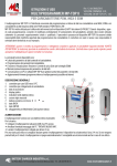
MP-TOP II MULTIPROGRAMMER FOR PSW AND MGX BATTERY CHARGERS OPERATING INSTRUCTIONS Rev. 1.2 - 08/06/2012 (FIRMWARE VERSION: 4.05 / MP-TOP II SW VERSION: PC 1.06) The MP-TOP II multiprogrammer is the necessary interface to program and read the data in the battery chargers of the MGX, EDM series and in the high frequency battery chargers of the Standard PSW, EXIDE PSW and ZHF series. MP-TOP II is also used to read the memorized data in Q-BATT devices and in the Q_PROJECT systems. Acting on the programming, this device enables to deeply modify the operating of the charger, therefore it only has to be used by qualified and properly educated personnel. The personnel owning such device assumes the responsibility of the changes carried out on the programming; the manufacturer is not in any case responsible for any damage due to improper use. WARNING: When the programming gets modified, it is compulsory to fill in and stick to the charger the provided label "SUITABLE FOR BATTERY" with the features of the correctly rechargeable battery. This operation is compulsory for normative reasons and safety. The label has to cover the original one. The main available functions are: - reading of the battery charger parameters and data - programming of the battery charger parameters - charge voltage and current display function (for EDM series only) - temporary storage of the parameters and of the already read data - communication with PC and MP-TOP II software to manage the parameters and data-files - firmware updating (internal multiprogrammer program), possible on-line through the Internet. 1 GENERAL DESCRIPTION 1. 2. 3. 4. 5. 6. 7. 8. 9. 10. USB-cable-connector to the PC connector for the battery charger link switch on key graphic display inner battery level indicator hidden lines cursor numerical keyboard with arrows BACK key ENTER key slot for Multimedia Card (future option) POWER SUPPLY 2 3 4 5 6 7 9 8 10 The multiprogrammer works with an inner rechargeable battery. To recharge: - connect the multiprogrammer to the USB port of a switched-on PC - clear the possible PC message “NEW HW FOUND” - leave connected for at least 3 hours - for a faster recharge we recommend to keep the multiprogrammer off The device has got about 3-4 hours’ autonomy . If no key gets pressed within 3 minutes, the multiprogrammer switches off automatically. It is recommendable to recharge once a month even if not used. SWITCHING ON Press the switch on key. The display will show the logo and will indicate: 1- the multiprogrammer internal firmware version 2- the enabled level (see section LEVELS) After 3 seconds the main menu appears (MainMenu) 1 2 BATTERY CHARGER INDUSTRY s.r.l. Via Pietro Nenni, 17 / 19 - 25010 Colombare di Sirmione (BS) - ITALY Tel. +39 030 9906010 - Fax +39 030 9906011 - E-mail: [email protected] - www.moriraddrizzatori.it P. IVA 02393720988 page 1 of 17 WARNING: In case of problems, it is possible to carry out a reset of device: press ENTER for 10 seconds. SELECTION COMMANDS To select a function among the different menus, press the arrows to choose the corresponding line. The selected line gets highlighted in white. Press ENTER to let the selection start. The arrow on the right indicates a submenu. To go back to the previous menu, press BACK. The display can show 3 lines and the title simultaneously: if the cursor on the hidden lines indicator (A) is not on the bottom, it means that pressing you can view other functions. A SWITCHING OFF To switch off the multiprogrammer, select the function Off in the main menu through the arrows , then press ENTER. If no key gets pressed within 3 minutes, the multiprogrammer switches off automatically. LANGUAGE To select the chosen language, select the function Options in the main menu through the arrows , then press ENTER. Select the function Language ENG in the “Options” menu through the arrows , then press ENTER. In this way only ENG gets selected. Select the chosen language through the arrows and press ENTER to confirm. The display will immediately update the notices in the selected language. Press BACK to go back to the main menu. The languages are: ITA = Italian ENG = English FRA = French DEU = German ESP = Spanish NED = Dutch BRIGHTNESS To change the display brightness, in the main menu select the function Options through the arrows , then press ENTER. Through the arrows , select the function Brightness in the “Options” menu, and then press ENTER. Set the desired brightness by selecting with the number keys: choose a value from 1 to 4. Press BACK to return to the main menu. LEVELS The multiprogrammer can be used in 3 different modes: - USER : User mode. It enables only reading procedures (no programming). We recommend this mode for the final user. - SERVICE : Technical service mode for Standard PSW, ZHF and MGX. It enables both reading and programming procedures. - MST-EX : Technical assistance mode for EXIDE PSW. To select the SERVICE or MST-EX mode, select the function Options in the main menu, then ENTER to confirm. Select the function Password and press ENTER to confirm. Type in the password and press ENTER to confirm. If everything is correct all the functions will get enabled and in the initial display the notice SERVICE or MST-EX will appear. WARNING: Ask the manufacturer for your password. CONNECTION TO THE BATTERY CHARGER In order to carry out the data reading or the parameter programming, connect battery charger and multiprogrammer through the proper cable. Check that the battery charger is disconnected from the mains supply. If the multiprogrammer displays Battery charger not found, check the connections. BATTERY CHARGER INDUSTRY s.r.l. Via Pietro Nenni, 17 / 19 - 25010 Colombare di Sirmione (BS) - ITALY Tel. +39 030 9906010 - Fax +39 030 9906011 - E-mail: [email protected] - www.moriraddrizzatori.it P. IVA 02393720988 page 2 of 17 The reading/programming operations can be carried out both with and without connection between battery and battery charger. If the battery is missing, the multiprogrammer will feed the battery charger as long as necessary. WARNING: Pay attention to the connecting operation to your battery charger: a wrong insertion of the programming connector will cause serious damages to both MP-TOP II and battery charger. Keep the red and black battery charger cables separated: a possible short circuit could cause damages to the multiprogrammer... If the multiprogrammer displays Update Programmer SW, it means that the battery charger code is unknown. Ask the manufacturer for further information and possibly update the multiprogrammer firmware (see section MULTIPROGRAMMER UPDATING). DATA READING Once the battery charger has been connected, select the function Readout in the main menu and press ENTER. The display shows Please wait… for some seconds, at the end of the reading the DataReading menu will appear: it allows to display the data and/or save them. Select the function View and press ENTER. The menu DataView will appear: it is possible to read its content through the keys . The displayed data are: - for the PSW, ZHF series: Voltage / Current / Cycle / Cap.C5 / Threshold / Block / Rental / Days / Pump Equal / C1(tot) / C2(disc) / C3(c/d) / C4(0-3h) / C5(3-6h) / C6(6-9h) / C7(+9h) - for PSW EXIDE series: Voltage / Current / Cycle / Threshold / Opp.Chrg. / Delay h C1(tot) / C2(disc) / C3(c/d) / C4(0-3h) / C5(3-6h) / C6(6-9h) / C7(+9h) - for the MGX series: Voltage / Current / Cycle / Threshold / C1(tot) / C2(disc) / C3(c/d) / C4(0-3h) C5(3-6h) / C6(6-9h) / C7(+9h) - for the EDM series: Voltage / Current / Cycle / Threshold / Eff.Fact. / Pump / Equal / Delay / Manual / C1(tot) / C2(disc) / C3(c/d) / C4(0-3h) / C5(3-6h) / C6(6-9h) / C7(+9h) - for the Q-BATT: From C1 to C27 counters For a detailed description see the DATA INTERPRETATION section. Select the last line Cycle Mem and press ENTER to display the details of the data corresponding to the last 22 charge cycles. It is possible to read the content through the keys . Every screen PSW, PSW EXIDE, ZHF, MGX and EDM will show: 123456- CYCLE NUMBER ERRORS CHARGE BY THE START CHARGE BY THE STOP CAPACITY STOP CONDITIONS : number of the charge cycle; 1 is the most recent, 22 is the oldest : code of the errors happened during the recharge (see section ERROR CODES) : initial voltage and charge current (after 5 minutes charging) : final voltage and charge current (by the stop) : total recharged capacity (in Ah) : charging interruption conditions (see section STOP CONDITIONS) 1 2 3 4 6 5 Every screen Q-Batt device will show: 1234- 2 NUMBER COUNTER VALUE COUNTER UNIT OF MEASURE PARAMETER DESCRIPTION 1 3 4 Through the keys you can read the contents of each counter. BATTERY CHARGER INDUSTRY s.r.l. Via Pietro Nenni, 17 / 19 - 25010 Colombare di Sirmione (BS) - ITALY Tel. +39 030 9906010 - Fax +39 030 9906011 - E-mail: [email protected] - www.moriraddrizzatori.it P. IVA 02393720988 page 3 of 17 DATA SAVING Press BACK to go back to the DataView menu. Select the function Save and press ENTER to save the data in the multiprogrammer. A number (associated to the file) will represent the name of the file to be saved. It is possible to delete the number (using BACK) and rewrite it, for example replacing it with the battery charger serial number. Press ENTER at the end to save the file. The display will confirm with the notice File …. File stored, press ENTER to go back to the menu DataView. The multiprogrammer can store at most 100 files, over that it will display: File not stored – Memory full. To delete memory see section ARCHIVES MANAGEMENT. The stored data will remain in memory even without feeding the multiprogrammer. To transfer files to a computer see section DATA TRANSFER TO THE COMPUTER. ARCHIVES MANAGEMENT Select the function Archive in the main menu and press ENTER: the menu Archive will appear. To display the files stored in the multiprogrammer select the function View and press ENTER. You enter the menu File List, here you can find the list of the stored files (the first of the list is the oldest, the last one is the most recent; if no file has been stored, the list is empty). Through the keys it is possible to select the desired file, press ENTER and the data will be displayed as described in section DATA READING. Press BACK to go back to the previous menu. To delete the stored files, select the function Delete in the menu Archive and press ENTER. You enter the menu DeleteArchive: you can see the function Confirm? No . Press ENTER to select No and change it into Yes through the keys , then press ENTER. The deleting is carried out and the notice All Files Deleted will appear. Press ENTER once again, then BACK to go back. WARNING: the deleted files can’t be recovered, we recommend to store them on the computer before deleting them (see section DATA TRANSFER TO THE COMPUTER). It is not possible to delete a single file. TESTER FUNCTION (EDM only) If connected to a battery charger of the EDM family, the MP-TopII allows to display the instantaneous values of battery voltage and charging current. To enable the TESTER feature, select the function Options in main menu, then ENTER to confirm. Select the function Charger and press ENTER to confirm. Select the function Tester r and press ENTER to confirm. On the display it appears: If you connect the MP-TopII to the charger during the charging cycle, the display changes to the visualization of the voltage and current of charge: WARNING: the current values higher than 255A are not viewable. Press BACK to return to the Charger menu and to exit from TESTER function. PROGRAMMING (only SERVICE and MST-EX) To modify the programming, connect the multiprogrammer to the battery charger. Select the function Program in the main menu and press ENTER. The display will show Please wait… for some seconds (while reading the data from the battery charger), at the end the menu Programming will appear: it allows to modify and save the programming. Select the function Modify and press ENTER to get to the menu DataProgram; through the keys it is possible to read its content. BATTERY CHARGER INDUSTRY s.r.l. Via Pietro Nenni, 17 / 19 - 25010 Colombare di Sirmione (BS) - ITALY Tel. +39 030 9906010 - Fax +39 030 9906011 - E-mail: [email protected] - www.moriraddrizzatori.it P. IVA 02393720988 page 4 of 17 The programmable data of the PSW and ZHF series are: - Cycle - Cap.C5 - Threshold - Block - Rental - Days - Pump – Equal. The programmable data of the EXIDE PSW series are: - Cycle - Current - Threshold - Opportunity Charge – Delay. The programmable data of the MGX series are: - Cycle - Threshold; The programmable data of the EDM series are: - Voltage* - Current* - Cycle - Threshold – Eff.Fact. – - Pump - Equal - Delay - Manual. * WARNING: In the EDM series these parameters should ALWAYS be programmed as per rating plate values of the charger. Different values can produce a malfunction of the charger and cause damage to the battery. For a detailed description see DATA INTERPRETATION section. Select the parameter to be modified through the keys , then press ENTER. The value of the parameter gets selected; to change its value: - Through the keys select the new value and press ENTER to confirm (this procedure is valid for the following parameters: - Cycle - Cap.C5 - Rental; in the Lith cycle: - I Charge - I Final) - Digit the numerical value. For example, if you want to write 2.40, digit 2 4 0 in succession and then press ENTER to confirm (this procedure is valid for the following parameters: - Threshold - Lock - Days - Pump – Equal Delay – Manual - Eff.Fact. For the Lith Cycle: Threshold V – Lock V). If you digit a wrong value, the parameter will not get modified. Press BACK for possible corrections. Press BACK to go back to the menu Programming. WARNING: the changes will be stored in the battery charger only after carrying out the following procedure; if you don’t carry it out, the previous programming will be operating. To transfer the changes to the battery charger, select the function SaveModif and press ENTER to confirm. The display shows Please wait… for some seconds; at the end the notice Battery Charger Updated will appear. The notice ID_0=….. is the identification code of the battery charger. DATA RESET (only SERVICE and MST-EX) If you recharge a new battery with a used battery charger, we recommend to reset the stored charging data. This allows to put the charge counters back to zero. In order to do this, connect the battery charger to the multiprogrammer and select the function Options in the main menu, press ENTER to confirm. Select the function Charger in the Options menu, press ENTER to confirm. Select the function Reset in the Charger menu and press ENTER to confirm. The display will show Please wait… for some seconds; at the end the notice Data Reset will appear. The notice ID_0=….. is the identification code of the battery charger. WARNING: the reset does not modify the battery charger programming. The deleted data can’t be recovered, we recommend to store them on the computer before deleting them (see section DATA TRANSFER TO THE COMPUTER). DATA INTERPRETATION Meaning of the PSW and ZHF battery chargers programmable parameters: VOLTAGE : Battery charger rated voltage (for example 24V); it can’t be modified CURRENT : Battery charger rated current (for example 30A); it can be modified by the manufacturer CYCLE : It allows to program the correct charging cycle according to the connected battery. - Pb13h suitable to the recharging in 13 hours of lead acid batteries. - Pb11h suitable to the recharging in 11 hours of lead acid batteries. - Pb8h suitable to the recharging in 8 hours of lead acid batteries. - Gel suitable to the recharging in 11 hours of GEL/AGM/DEEP-CYCLE batteries. - Lith suitable to the recharging of Lithium batteries (Li-Ion). See the charging cycles charts in Fig.1. CAP. C5 : Battery capacity to be recharged (specified in Ah, 5 hours’ rate – C5) BATTERY CHARGER INDUSTRY s.r.l. Via Pietro Nenni, 17 / 19 - 25010 Colombare di Sirmione (BS) - ITALY Tel. +39 030 9906010 - Fax +39 030 9906011 - E-mail: [email protected] - www.moriraddrizzatori.it P. IVA 02393720988 page 5 of 17 Table of the CAP. C5 programmable values: GEL Pb 8h Pb 11h Pb 13h Lith 12 A 30-120 Ah 30-80 Ah 30-120Ah 30-140Ah ---- 15 A 60-160 Ah 60-80 Ah 60-160 Ah 60-180 Ah ---- 20 A 80-200 Ah 80-120 Ah 80-200 Ah 80-240 Ah ---- 25 A 120-240 Ah 120-160 Ah 120-240 Ah 120-300 Ah ---- 30 A 120-300 Ah 120-180 Ah 120-300 Ah 120-360 Ah ---- 40 A 180-420 Ah 180-240 Ah 180-420 Ah 180-480 Ah ---- 45 A 180-480 Ah 180-270 Ah 180-480 Ah 180-540 Ah ---- 50 A 180-480 Ah 180-300 Ah 180-480 Ah 180-600 Ah ---- 55 A 180-540 Ah 180-330 Ah 180-540 Ah 180-660 Ah ---- 60 A 180-600 Ah 180-360 Ah 180-600 Ah 180-720 Ah ---- 65 A 180-660 Ah 180-360 Ah 180-660 Ah 180-780 Ah ---- 70 A 180-720 Ah 180-420 Ah 180-720 Ah 180-840 Ah ---- 80 A 300-840 Ah 300-480 Ah 300-840 Ah 300-960 Ah ---- 90 A 270-900 Ah 270-540 Ah 270-900 Ah 270-1080 Ah ---- 120 A 360-1200 Ah 360-720 Ah 360-1200 Ah 360-1400 Ah ---- 160 A 600-1600 Ah 600-960 Ah 600-1600 Ah 600-2000 Ah ---- 240 A 720-2400 Ah 720-1400 Ah 720-2400 Ah 720-2800 Ah ---- Warning: In some models available programmable values may be different. According to the selected value, the battery charger modifies the supplied current in order to get a correct recharge. Insert the battery C5 value (5 hours’ rate). If the programmable values do not exactly correspond to the C5 value of your battery, always choose the immediately higher available value (for example: for 170Ah, you can select 180Ah). Wishing to slightly reduce the recharging time, it is possible to select a higher capacity value than the real one. For instance, if your C5 battery value is 180Ah, it is possible to program 200Ah without causing damages. Selecting even higher values can be dangerous for the battery; in any case ask the manufacturer for advice. If you only know the battery C20 value, it is possible to estimate the C5 value: C5 = C20 x 0.8 (for example 100Ah in C20 correspond to about 80Ah in C5) I CHARGE : Active only if the programmed cycle is the Lith type. This parameter sets the maximum charging current of Lith cycle and it may take different values, depending on the model of battery charger. THRESHOLD : Threshold voltage in V/c. Programmable values: from 2.35 to 2.45 V/c. If the programmed cycle is Pb type, this parameter represents the threshold between starting and final charge, typical value 2.40V/c. If the programmed cycle is Gel type, this parameter represents the maximum charging voltage. Such value is normally provided by the battery manufacturer. Typical values are included between 2.35 and 2.40 V/c. V THRESHOLD : Active only if the programmed cycle is the Lith type. This parameter is expressed in absolute Volts and represents the maximum value of charging voltage. WARNING: This value must be carefully selected according to specific characteristics of the battery normally provided by the manufacturer. The limits of programming are described in table Tab.1. LOCK : If the programmed cycle is GEL or Pb type, this parameter represents the minimum voltage for discharged battery (V/c). Programmable values: from 1.50 to 1.85 V/c. It allows to program the block voltage for discharged battery. This parameter is only meaningful if the charger is on-board installed and the battery is therefore always connected. When the voltage of the battery being discharged gets under the programmed value and remains there for at least 10 consecutive seconds, the block gets activated (block LED and relay: active). Proceed with the recharging in order to start the vehicle. WARNING: the vehicle gets actually blocked if the auxiliary block contact has been really connected to the vehicle. V LOCK : Active only if the programmed cycle is the Lith type. This parameter is expressed in absolute Volts and represents the maximum value of voltage reachable by the battery in charge. BATTERY CHARGER INDUSTRY s.r.l. Via Pietro Nenni, 17 / 19 - 25010 Colombare di Sirmione (BS) - ITALY Tel. +39 030 9906010 - Fax +39 030 9906011 - E-mail: [email protected] - www.moriraddrizzatori.it P. IVA 02393720988 page 6 of 17 If the battery during charging reaches the programmed value, the charging cycle is interrupted. WARNING: this value must be carefully selected according to specific characteristics of the battery normally indicated by the manufacturer. For the limits see the table below. Tab.1: Programmable values of V Threshold and V Lock in Lithium-IUIa cycle: Nominal Voltage 12 V 24 V 36 V 48 V 72 V 80 V 84 V V Threshold min 14.1 V 28.2 V 42.3 V 56.4 V 84.6 V 94.0 V 98.7 V max 14.7 V 29.4 V 44.1 V 58.8 V 88.2 V 98.0 V 102.9 V V Lock min 14.2 V 28.4 V 42.6 V 56.9 V 85.3 V 94.8 V 99.5 V max 16.5 V 33.0 V 49.5 V 66.0 V 99.0 V 110.0 V 115.0 V I FINAL : Programmable parameter only if the programmed cycle is the Lith type. This parameter represents the value of charging current in the final phase of Lithium cycle. The programmable values are different according to the various battery charger models. RENTAL : Rental or maintenance management. Programmable values: Off : the function is inactive On : when the days expire, it signals and it blocks the vehicle Alarm : when the days expire, it signals, but it does not block the vehicle Display of the battery charger: the two CHARGE and STOP LEDs flash alternately. WARNING: the vehicle gets actually blocked if the auxiliary block contact has been really connected to the vehicle. DAYS : Rental or maintenance period, in days. Programmable values: from 0 to 600 days. The counting starts when the programming gets activated. It only works if the charger is on-board installed and the battery is therefore always connected. PUMP : Pump cycle management: you can program only on devices with the pump plant, otherwise go to the next parameter. This parameter is active only on Pb type programmed cycles. You can take values from 0 to 4: 0 - inactive pump. 1 - Pump always on during charging. 2 - Pump active for the first 30 minutes of battery, after 3 min. ON and 7 min. OFF until the Stop. 3 - Pump active in ON phase for 3 min. and in OFF phase for 10 min. from Start to Stop. 4 - Idem point 3, but the pump is active with battery voltage higher than 2.19 V/c. EQUAL : Equalization charge management This parameter is active only on devices Pb-cycle programmed. Equalization is an additional charge carried out after automatic Stop and it consists of 12 charge pulses (10 minutes) alternated with 50 minutes of waiting. Depending on the programmed value, the Equalization may include the FORMATION phase. When the Formation is on, the charger is running, an hour after from the automatic Stop, an additional charge (1 hour), before the equalization start. The Formation is active only in the first 30 charge cycles and then will be automatically disabled. EQUAL can take from 0 to 4 values: 0 - Equalization not active 1 - Equalization consists: Formation - 12 hours waiting - Equalization 2 - Equalization started after 12 hours from the Automatic Stop 3 - Equalization consists of: Formation - 1 hour waiting - Equalization 4 - Equalization executed after 1 hour from Automatic Stop For a more detailed description of the cycles with EQUAL see Fig.4. Meaning of programmable parameters in the EXIDE PSW battery charger: VOLTAGE: Nominal voltage of the charger (ex. 24V), not modifiable value. CURRENT: Nominal current of the charger (ex. 30A), modifiable value, depending on the models. CYCLE: You can select the desired charge cycle. BATTERY CHARGER INDUSTRY s.r.l. Via Pietro Nenni, 17 / 19 - 25010 Colombare di Sirmione (BS) - ITALY Tel. +39 030 9906010 - Fax +39 030 9906011 - E-mail: [email protected] - www.moriraddrizzatori.it P. IVA 02393720988 page 7 of 17 Cycles available are: - GEL charge cycle for Gel battery according to the EXIDE GEL specification - L01 charge cycle for free acid Pb batteries, with pulses-phase, according to EXIDE specific - L02 charge cycle for free acid Pb batteries, according to EXIDE specific THRESHOLD: Parameter active only with the programming L01 or L02 cycles. This parameter represents the threshold between the initial and final charge, typical value: 2.40V/c. Value programmable from 2.35 at 2.45 V/c. OPPORTUNITY CHARGE: Parameter active with the programming cycles L01 or L02 only. The activation of OPPORTUNITY CHARGE function is in according to the EXIDE specific: - ON: Function enabled - OFF: Function disabled DELAY START: This parameter allows you to activate a programmable delay of charging cycle start. The parameter can take values from 0 to 24 and represents the number of hours of waiting before the start of the charge cycle. The battery charger activates the programmed delay from the time it is powered by the mains and is connected to the battery. Meaning of the MGX battery chargers programmable parameters: CYCLE : It allows to program the correct charging cycle according to the connected battery. - Pb13h suitable to the recharging in 13 hours of lead acid Pb batteries - Gel suitable to the recharging in 11 hours of GEL/AGM/DEEP-CYCLE batteries See the charging cycles charts in Fig.2 THRESHOLD : Threshold voltage in V/c. Programmable values: from 2.35 to 2.45 V/c. If the programmed cycle is Pb type, this parameter represents the threshold between starting and final charge, typical value 2.40V/c. If the programmed cycle is Gel type, this parameter represents the maximum charging voltage. Such value is normally provided by the battery manufacturer. Typical values are included between 2.35 and 2.40 V/c. Meaning of the EDM battery chargers programmable parameters: VOLTAGE : Nominal voltage of the charger (value from rating plate values). CURRENT : Nominal current of the charger (value from rating plate values). CYCLE : It allows to program the correct charging cycle according to the connected battery. - Wa suitable for recharging in 12 hours of lead-acid Pb batteries. - WoWa suitable for recharging in 8 hours of lead-acid Pb batteries. See the charging cycles charts in Fig.3 THRESHOLD :Threshold voltage in V/cell. Programmable values: from 2.35 to 2.45 V/cell. This parameter represents the threshold between starting and final charge, typical value 2.40 V/cell. EFF. FACT. PUMP EQUAL :This parameter allows to modulate the duration of the charging cycle to optimize the efficiency. This parameter is programmable from 0.70 to 1.30. The value 1.00 (typical) provides the optimal charge of the battery. Setting the value from 0.70 to 1.30, you can modulate the duration of the final charge from -30% to +30%. :Pump cycle management: you can program only on devices with the pump plant, otherwise go to the next parameter. This parameter is active only on Pb type programmed cycles. You can take values from 0 to 4: 0 - inactive pump. 1 - Pump always on during charging. 2 - Pump active for the first 30 minutes of battery, after 3 min. ON and 7 min. OFF until the Stop. 3 - Pump active in ON phase for 3 min. and in OFF phase for 10 min. from Start to Stop. 4 - Idem point 3, but the pump is active with battery voltage higher than 2.19 V/cell. : Equalization charge management This parameter is active only on devices Pb-cycle programmed. Equalization is an additional charge executed after automatic Stop and it consists of 12 charge pulses (10 minutes) alternated with 50 minutes waiting. Depending on the programmed value, the Equalization may include the FORMATION phase. BATTERY CHARGER INDUSTRY s.r.l. Via Pietro Nenni, 17 / 19 - 25010 Colombare di Sirmione (BS) - ITALY Tel. +39 030 9906010 - Fax +39 030 9906011 - E-mail: [email protected] - www.moriraddrizzatori.it P. IVA 02393720988 page 8 of 17 When the Formation is on, the charger is running, an hour after from the automatic Stop, an additional charge (1 hour), before the equalization starts. The Formation is active only in the first 30 charge cycles and then will be automatically disabled. EQUAL can take from 0 to 4 values: 0 - Equalization not active 1 - Equalization consists: Forming - 12 hours waiting - Equalization 2 - Equalization started after 12 hours from the Automatic Stop 3 - Equalization consists of: Training - 1 hour waiting - Equalization 4 - Equalization carried out after 1 hour from Automatic Stop For a more detailed description of the cycles with EQUAL see Fig. 4. DELAY START MANUAL :This parameter allows you to activate a programmable delay of charging cycle start. The parameter can take values from 0 to 10 and represents the number of hours of waiting before the start of the charge cycle. The battery charger activates the programmed delay from the time it is powered by the mains and is connected to the battery. If the set value is different from 0, the charger will carry out the DELAY START in all cycles. To disable the DELAY START set this parameter to 0. :This parameter enables you to activate a charge of a predetermined duration. This parameter can assume values from 0 to 50 and represents the hours of charge that the machine will follow when it is powered from the mains and connected to the battery. The manual charge is performed only once, the parameter is automatically reset at the end of the cycle. INTERPRETATION OF THE STORED DATA Meaning of the stored counters in the PSW, EXIDE PSW, ZHF, MGX and EDM battery chargers: - C1(tot) Charging cycle counter: it indicates the total charging cycles lasting more than 5 minutes. It allows to understand how many times the charger has been connected to the battery in order to start a recharge. - C2(dis) Deep discharge counter: it indicates the number of deep discharges carried out by the battery (battery voltage lower than the programmed value in parameter LOCK). This counter only works if the charger is onboard assembled with always connected battery. It allows to understand how many times the battery has been completely discharged. - C3(c/d) Simultaneously charged/discharged battery cycle counter: it indicates how many times the battery has been used (application of a load) during the recharge. This operation is technically possible, but it is not recommended not to reduce the battery life - C4(0-3h) Charging cycle counter (completed in less than 3 hours): it indicates how many times the battery has been little discharged and it has been completely recharged - C5(3-6h) Charging cycle counter (completed in 3 - 6 hours): it indicates how many times the battery has been rather discharged and it has been completely recharged - C6(6-9h) Charging cycle counter (completed in 6 - 9 hours): it indicates how many times the battery has actually been discharged and it has been completely recharged - C7(+9h) Charging cycle counter (completed in more than 9 hours): it indicates how many times the battery has extremely been discharged and it has been completely recharged. The counters C4, C5, C6, C7 give a statistical indication on how much the battery has been exploited during its life (long charges happen on very discharged batteries...! And vice versa). Adding up the counters C4, C5, C6, C7 you get the number of automatically completed charges. It is sufficient to subtract this sum from counter C 1 in order to know how many times the operator has interrupted the charge (incomplete charging cycle). Example: C1=100 C4=12 C5=27 C6=23 C7=5 12+27+23+5=67 That means that the operator correctly charged the battery 67 times, while he interrupted the charging cycle 100-67=33 times. This behaviour can create damages to the battery. Through the value of counters C4, C5, C6, C7 you can moreover understand that this battery gets rather little discharged. BATTERY CHARGER INDUSTRY s.r.l. Via Pietro Nenni, 17 / 19 - 25010 Colombare di Sirmione (BS) - ITALY Tel. +39 030 9906010 - Fax +39 030 9906011 - E-mail: [email protected] - www.moriraddrizzatori.it P. IVA 02393720988 page 9 of 17 Meaning of the stored data in the PSW, PSW EXIDE, ZHF and MGX battery chargers: For the last 22 charging cycles following data get stored: - CYCLE NUMBER : cycle number: 1 is the most recent, 22 is the oldest; over they get deleted - ERRORS : code of the errors happened during the recharge (see section ERROR CODES) - CHARGE BY THE START : initial voltage (V/c) and charge current (after 5 minutes charge) - CHARGE BY THE STOP : final voltage (V/c) and charge current (by the stop) - CAPACITY : total recharged capacity (in Ah) - STOP CONDITIONS : charging interruption conditions (see section STOP CONDITIONS) It is impossible, under some situations, to store some data correctly; if so, the stored value is zero. Every value of a new battery charger is zero. ERROR CODES “E 001” : Inner overheating detected. The thermic protection progressively reduces the supplied current. If overheating goes on, the battery charger interrupts the charging and signals the trouble letting the two LEDs flash contemporarily “E 011” : Transformer overheating (only for MGX). The thermic protection progressively reduces the supplied current. If overheating goes on, the battery charger interrupts the charging and signals the trouble letting the two LEDs flash contemporarily “E 012” : Broken fan. The charging gets immediately interrupted (only for some models) “E 006” : Problem with the pump (only for models with pump). It takes a longer time to complete the charging “E 007” : Net feeding failure during the charge cycle. STOP CONDITIONS They indicate how the charging cycle has ended: “F 001” “F 002” “F 003” “F 004” “F 005” : Charge interrupted before an automatic stop (through the STOP key or, for the on-board installed models, disconnecting the feeding and using the vehicle) : Charge regularly ended (automatically) : Charge with equalization regularly ended (automatically) : Charge interrupted disconnecting the battery (if so, the stored final voltage and current values have no meaning) : Safety timer. Charge interrupted because the battery voltage has not reached the correct value within the expected time Meaning of the stored data in the Q-BATT device The stored data by the Q-Batt device resume the conditions for using the Q PROJECT system, enclosing data and counters relating to the charging and discharging conditions of the battery charger, relating to the correct use of the battery charger and relating to the respect of the storage rules and the maintenance efficiency of the total system. The meaning of the Q-Batt device data is: • COUNTERS FROM 1 TO 21: FOR CHARGE AND DISCHARGE MANAGEMENT AFTER THE INSTALLATION 01 - Working Days : Days past the installation on the vehicle. 02 - Cycles of Charge : Total number of charge cycles. 03 - Charges less than 90% : Interrupted charges (recharged battery less than 90%). 04 - Charges more than 90% : Quick charges (recharged battery more than 90%). 05 - 100% charges : 100% charged battery. 06 - Complete Daily Charges : Complete charges (at least 8 hours duration). 07 - Maintenance Charges with : Complete charges (at least 12 hours duration). 08 - Anomalous Charges : Charges by the charge cycle not compatible with ' Q-System '. 09 - Maximum Charge Voltage : Maximum voltage reached by the charging battery. 10 - Battery Voltage 1 (Q-Batt) : Maximum voltage reached by the battery 1 (Q-Batt). 11 - Battery Voltage 2 (Q-Power) : Maximum voltage reached by the battery 2 (Q-Power). 12 - Unbalance maximum batteries : Maximum voltage difference between two batteries. 13 - Cycles with Unbalanced Batteries : Charge cycles executed with imbalance greater than allowed. 14 - Discharging to the bottom : Discharging 80% of nominal capacity. 15 - Excessive discharging : Discharging more than 80% of nominal capacity. 16 - Minimum voltage in discharging : Minimum voltage reached by the battery discharge. 17 - Battery Overheat : Charge cycles with battery temperature exceeding the maximum allowed (50°C). 18 - Maximum battery temperature : Maximum temperature reached by the battery. 19 - Left discharged battery : Battery discharged and not recharged within 24 hours. BATTERY CHARGER INDUSTRY s.r.l. Via Pietro Nenni, 17 / 19 - 25010 Colombare di Sirmione (BS) - ITALY Tel. +39 030 9906010 - Fax +39 030 9906011 - E-mail: [email protected] - www.moriraddrizzatori.it P. IVA 02393720988 page 10 of 17 20 - Maintenance interrupted : Battery not remain in office during the long downtime. 21 - Maximum time without maintenance : Maximum without recharge period. • COUNTERS FROM 22 TO 25: FOR THE STORAGE PERIOD BEFORE INSTALLATION Note: The “balance” means a charge cycle of the two batteries connected in parallel and executed with specific battery charger Q-Balance (accessory to the 'Q-System') 22 - Maximum time between two balances 23 - Time past by last balance 24 - Balance 25 - Excessive self-discharge • COUNTERS FROM 26 TO 27: RELATING TO POSSIBLE TAMPERING OF SYSTEM 26 - Tampering system 27 - Disconnecting system : The maximum time spent in storage between two balances. : Maximum time since the last balance or start of storage. : Number of balances executed in storage. : Using battery or battery voltage too low in storage owing to excessive self-discharge (necessary balancing not executed) : Tampering found with connection between Q- Batt and Q-Power : Disconnection of the Q-Batt device from the battery. UNPROGRAMMABLE BATTERY CHARGERS Some particular battery chargers (with special charging cycles) are unprogrammable, but they have got a data memory. The reading and programming functions for these models are the following: - DATA READING : normally allowed, it only displays the counters and the 22 stored cycles - PROGRAMMING : the notice ID_0=255 Unprogrammable Charger appears All other functions do not change. BATTERY CHARGER INDUSTRY s.r.l. Via Pietro Nenni, 17 / 19 - 25010 Colombare di Sirmione (BS) - ITALY Tel. +39 030 9906010 - Fax +39 030 9906011 - E-mail: [email protected] - www.moriraddrizzatori.it P. IVA 02393720988 page 11 of 17 Fig.1: Charge curves available on PSW and ZHF GEL charge cycle In: function of Cap.C5 programmed In = Cap.C5/10 V0: 1.90 V/c V1: programmed value of threshold (V/c) V2: 2.10 V/c V3: 2.30 V/c T0: 1 hour max. T1: 12 hour max. T2: =T1 (2 hours < T1< 5 hours) T3: no limits T4: 6 hours max. Pb11h e Pb13h charge cycle In: function of Cap.C5 programmed In = Cap.C5/10 in cycle Pb11h In = Cap.C5/12 in cycle Pb13h V0: 1.90 V/c V1: programmed value of threshold (V/c) V2: 2.10 V/c V3: 2.30 V/c T0: 1 hour max. T1: 13 hours max. T2: = 0,6 T1 (1 hour < T2 < 3.5 hours) T3: No limits T4: 6 hours max. Pb8h charge cycle In: programmed Cap.C5 value In = Cap.C5/6 V0: 1.90 V/c V1: programmed threshold value (V/c) V2: 2.10 V/c V3: 2.30 V/c T0: 1 hour max. T1: 8 hours max. T2: = 1,2 T1 (1 hour < T2 < 3.5 hours) T3: No limits T4: 6 hours max. Lith-IUIa charge cycle In: Value I programmed charge If : Final value I programmed V0 V1 Prog. 12V 11.4 14.1 14.7 24V 22.8 28.2 29.4 36V 34.2 42.3 44.1 48V 45.6 56.4 58.8 72V 68.4 84.6 88.2 80V 76.0 94.0 98.0 84V 79.8 98.7 102.9 Min. Max. V2 Prog. 14.2 16.5 28.4 33.0 42.6 49.5 56.9 66.0 85.3 99.0 94.8 110.0 99.5 115.0 Min. Max. V3 12.6 25.2 37.8 50.4 75.6 84.0 88.2 V4 13.8 27.6 41.4 55.2 82.8 92.0 96.6 T0: 1 hour max, T1: 12 hours max. T2: 6 hours max. T3: 4 hours max. Note: The manufacturer reserves the right to make changes without notice. BATTERY CHARGER INDUSTRY s.r.l. Via Pietro Nenni, 17 / 19 - 25010 Colombare di Sirmione (BS) - ITALY Tel. +39 030 9906010 - Fax +39 030 9906011 - E-mail: [email protected] - www.moriraddrizzatori.it P. IVA 02393720988 page 12 of 17 Fig.2: Charge curves available on MGX GEL charge cycle I1 : nominal current of battery charger U1: programmed threshold T1: 12 hours max. T2: = T1 (min 2h – max 5h) T3: No limits Pb charge cycle I1 : nominal current of battery charger U1: 2.40 V/c T1: 13 hours max. T2: = 0.6 T1 (min 1h – max 4h) T3: No limits Note: The manufacturer reserves the right to make changes without notice. Fig.3: Charge curves available on EDM Wa charge cycle V1 : Programmable T1: 12 hours max. T2 : without Pump = 0.8 T1 (min. 30min – max 4h) * Eff. Fact. with Pump = 0.4 T1 (min. 30min. – max. 2h) * Eff. Fact. T3: 8 hours WoWa charge cycle V1 : Programmable T1: 8 hours max. T2: without Pump = 1.3 T1 (min. 30min – max 3,5h) * Eff. Fact. with Pump = 0.65 T1 (min. 30min – max 1h 45’) * Eff. Fact. T3: 8 hours Note: The manufacturer reserves the right to make changes without notice. BATTERY CHARGER INDUSTRY s.r.l. Via Pietro Nenni, 17 / 19 - 25010 Colombare di Sirmione (BS) - ITALY Tel. +39 030 9906010 - Fax +39 030 9906011 - E-mail: [email protected] - www.moriraddrizzatori.it P. IVA 02393720988 page 13 of 17 Fig.4: Characteristics of charge cycles with EQUALIZATION EQUAL MODE 1 EQUAL MODE 2 EQUAL MODE 3 EQUAL MODE 4 Note: The manufacturer reserves the right to make changes without notice. “MP-TOP II PC” SOFTWARE The MP-TOP II PC software allows to transfer the files from the multiprogrammer to the PC, manage an archive, print the data charts, update the multiprogrammer firmware. SOFTWARE INSTALLATION ON THE COMPUTER To install the software, insert the CD, open the “MP-TOP II PC” folder and click twice on SETUP. It creates a new folder C:\MP-TOP II PC and a new icon on the desktop. In order to proceed, click twice on the new icon “MP-TOP II PC”. The program runs correctly on WINDOWS 2000, XP and W7. FUNCTIONS AVAILABLE ON THE COMPUTER DOWNLOAD PROGRAMMER : it allows to transfer the files from the multiprogrammer to the PC SAVE : it allows to save the selected file in the desired folder LOAD : it allows to load a file stored on the PC PRINT : it allows to print the displayed data table The functions SAVE/LOAD/PRINT use the typical WINDOWS systems for the file managing. Every time a file is loaded from the multiprogrammer or from the folders on the PC, the list “FILES LIST” gets deleted. The files saved on the PC have got a .dat extension and can be sent per e-mail. The e-mail addressee can read the file only through the MP-TOP II software. DATA TRANSFER TO THE COMPUTER To transfer the data from the multiprogrammer to the PC it is necessary to connect the USB cable. Switch on the multiprogrammer and press the key DOWNLOAD PROGRAMMER on the PC. If the notice “No device connected” appears, try to press the key DOWNLOAD PROGRAMMER once again. BATTERY CHARGER INDUSTRY s.r.l. Via Pietro Nenni, 17 / 19 - 25010 Colombare di Sirmione (BS) - ITALY Tel. +39 030 9906010 - Fax +39 030 9906011 - E-mail: [email protected] - www.moriraddrizzatori.it P. IVA 02393720988 page 14 of 17 If the message appears once again, check if the multiprogrammer is on and control the USB connection. When the multiprogrammer displays Please wait… it begins to send files to the PC. At the end, the complete list of the stored files will appear on the PC in the column “FILE LIST”. Select the desired file to read its content directly on the screen. If the data file is PSW, ZHF or MGX, automatically open the STANDARD screen: If the data file is PSW EXIDE, automatically open the EXIDE screen: BATTERY CHARGER INDUSTRY s.r.l. Via Pietro Nenni, 17 / 19 - 25010 Colombare di Sirmione (BS) - ITALY Tel. +39 030 9906010 - Fax +39 030 9906011 - E-mail: [email protected] - www.moriraddrizzatori.it P. IVA 02393720988 page 15 of 17 If the data file is EDM, automatically open the EDM screen: If data file is belonging ot Q-BATT device, automatically open the Q-PROJECT screen: The cells in the chart first lines (DATA, CUSTOMER, BATTERY CHARGER, BATTERY, NOTES) can be filled in with the corresponding data. All other cells contain unmodifiable data. We recommend to fill in all the available cells and to create an archive containing one folder for each customer. BATTERY CHARGER INDUSTRY s.r.l. Via Pietro Nenni, 17 / 19 - 25010 Colombare di Sirmione (BS) - ITALY Tel. +39 030 9906010 - Fax +39 030 9906011 - E-mail: [email protected] - www.moriraddrizzatori.it P. IVA 02393720988 page 16 of 17 LANGUAGE SELECTION To change the language, select Option , then in “Select language” choose one language and confirm with OK . MULTIPROGRAMMER UPDATING If you want to update the firmware (multiprogrammer internal software) follow this procedure: - Connect the multiprogrammer to the PC through the USB cable, then switch it on; - Press Options on the PC and then Search to select the program “FirmwareMP-TOP II V xxx.chx”, where the xxx number represents the revision level; - Press Download Firmware to start the download; - The multiprogrammer will display USB RECEPTION xxx Kbyte where xxx represents the number of downloaded Kbytes; - Once it gets to 128 it displays WAIT... (about 2 minutes); - Then the name of the downloaded file appears: FirmwareMP-TOP II V xxx; - Press ENTER to continue; - It displays Please wait... (about 2 minutes) once again; The operation is over when the initial display with logo and updated revision level appears. WARNING: When the installation is complete, insert specific password to bring the MPTOPII in SERVICE or MST-EX mode, following these operating instructions carefully (see pag.2, LEVELS paragraph). The updated firmware revisions will be available on-line in the Internet manufacturer’s site. Note: The manufacturer reserves the right to make changes without notice. BATTERY CHARGER INDUSTRY s.r.l. Via Pietro Nenni, 17 / 19 - 25010 Colombare di Sirmione (BS) - ITALY Tel. +39 030 9906010 - Fax +39 030 9906011 - E-mail: [email protected] - www.moriraddrizzatori.it P. IVA 02393720988 page 17 of 17 CONNESSIONE AL CARICABATTERIE CONNECTION TO BATTERY CHARGER LADEGERÄTE-VERBINDUNG CONNEXION AU CHARGEUR Cavo con spina RJ45 + adattatore Cable with RJ45 plug + adapter Kabel mit RJ45-Stecker + Adapter Câble avec fiche RJ45 + adaptateur Connessione con adattatore (per MGX e PSW senza presa RJ45) Connection with adapter (for MGX and PSW without RJ45 socket) Verbindung mit Adapter (für MGX und PSW ohne RJ45-Steckdose) Connexion avec adaptateur (pour MGX et PSW sans prise RJ45) MGX PSW Connessione a caricabatterie a bordo con adattatore On-Board charger connection with adapter An Bord-Ladegeräte-Verbindung mit Adapter Connexion au chargeur embarqué avec adaptateur (pag.1/1 rev.04/10/2010) PSW, ZHF e EDM con connessione RJ45 PSW, ZHF and EDM with RJ45 connection PSW, ZHF und EDM mit RJ45-Verbindung PSW, ZHF et EDM avec connexion RJ45 PSW ZH F EDM