1
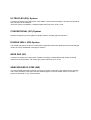
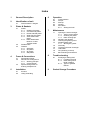
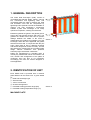
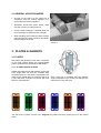
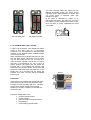
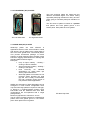
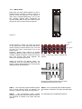
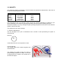
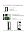
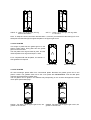
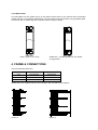
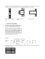
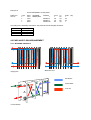
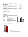
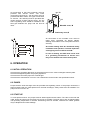
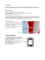
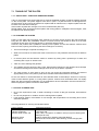
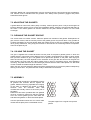
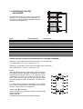
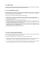
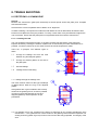
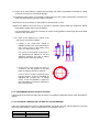
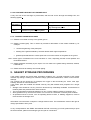
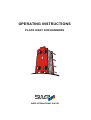
OPERATING INSTRUCTIONS
PLATE HEAT EXCHANGERS
SWEP INTERNATIONAL PHE AB
ULTRA FLEX (GX)- System
A system for heating and cooling fluids. With SWEP´s unique patented design, Ultra Flex asymmetrical
flow channels can be obtained
Ultra Flex system is available in 19 different plate sizes from 0.07 m2 to 3.3 m2.
CONVENTIONAL (GC)-System
Normal herringbone (chevron) pattern is ideally suited for handling aqueous solutions.
DOUBLE WALL (GD)-System
The double wall plate is perfect for a wide field of application where inter leaking of the heat exchanged
media can cause undesirable or dangerous reaction.
WIDE GAP (GF)
A system for heating and cooling fluids. Suitable for strongly contaminated media, fluids containing
solids and viscous products with a wide gap in flow channel of up to 12 mm
SEMI WELDED PLATES (GW)
The semi-welded plate heat exchanger consist of a number of plate pair ( also referred to an element)
and a frame assembly. Plate pairs are laser welded together to form a sealed channel or element. A
system for ammonia or very corrosive fluids.
Index
1
2
General Description
3.2
3.3
4
Plates
3.1.1
3.1.2
3.1.3
3.1.4
3.1.5
Ultraflex GX plates
Convential GC plates
Double wall GD plates
Wide Gap GF-plates
Semi welded GWplates
3.1.6 Plate Identification
Number of Heat
Transfer Plates
Suitable Glue
Gaskets
3.3.1 GX-plates
3.3.2 GC-plates
3.3.3 GF-plates
3.3.4 GW-plates
Frame & Connections
4.1
4.2
4.3
5
General advice / dangers
Plates & Gaskets
3.1
5.1
5.2
7
7.2
7.3
7.4
7.5
7.6
7.7
7.8
7.9
8
Erection
Lifting & handling
Opening the heat exchanger
7.1.1 Taking out the plates
7.1.2 Cleaning the plates
7.1.3 Plate cleaning tips
Adjusting the gaskets
Cleaning the gasket groove
Suitable gasket glue
7.4.1 Glueing the gasket
Assembly
Tightening the heat exchanger
Lubrication
CIP (Cleaning In Place)
Back Flushing and strainers
Trouble shooting
8.1
9
Initial operation
Pumps
Start-up
Venting
Shut-down
6.5.1 Storing the PHE
Maintenance
7.1
Specification Sheet
Pass & Flow arrangement
4.2.1 Working principle
4.2.2 Cooler Module
Special arrangement for
draining multipass unit
Installation
Operation
6.1
6.2
6.3
6.4
6.5
Identification of unit
2.1
3
6
Rectifying a leaking PHE
8.1.1 Localizing the leak
8.1.2 Determining which
liquid is leaking
8.1.3 Types of gaskets
failures
Gasket Storage Procedure
1. GENERAL DESCRIPTION
The Plate Heat Exchanger (PHE) consist of
corrugated heat transfer plates, frames, carrying
bar, connections and tightening bolts. The
corrugated plates are held in between the fixed
and moveable cover and are compressed by
tightening bolts. Optional shrouds are available on
request. The heat exchanger`s construction
enables a plate heat exchanger to be easily
opened for inspection, cleaning and extension.
Elastomer gaskets are glued in the gasket groove
around the heat transfer surface and holes. The
gaskets are double around the holes to prevent
leakage between the media. In the event of
gasket failure the medium runs straight out of the
exchanger. When the unit is tightened, the gasket
seal the structure and, in conjunction with the port
holes, allow fluids to flow in alternate channels
and almost always flow counter-currently. The thin
fluid interspace coupled with the corrugated plate
design induces turbulence that produces
extremely high heat transfer coefficients.
Plates are manufactured in standard sizes in
virtually any material that can be cold worked. The
size, number and arrangement of the plates is
contingent upon the duty to be performed.
Accordingly, the units are custom designed or
each application.
Picture 1.
2. IDENTIFICATION OF UNIT
Each SWEP PHE is provided with a machine
plate attached to the fixed cover. It gives details
of:
1. Plate heat exchanger type
2. Serial number
3. Year of construction
4. Channel arrangement
5. Permitted working pressure range (bar)
6. Permitted working temperature range (°C)
MACHINE PLATE
Picture 2.
2.1 GENERAL ADVICE/DANGERS
• All work on the PHE is to be carried out in
compliance with the existing regulation, e.g.
the accident prevention regulation
• Shut-down should take place slowly, make
sure the unit NOT is under pressure.
• Cool the heat exchanger. If possible allow the
heat exchanger to stand and cool overnight.
• When handling heat exchanger plates. Always
USE GLOVES to prevent injuries to the handsthe plate edges are sharp!
Picture 3
3. PLATES & GASKETS
3.1 PLATES
The plates and gaskets are the main component
of your PHE. Please always use original SWEP
parts to guarantee the performance and lifetime.
3.1.1 ULTRAFLEX (GX) PLATES
SWEP International PHE AB Ultraflex means that
every single plate can form two channels. With
the gasket groove in the plate`s neutral plane the
plate can be rotated about its x-axis as well as its
y-axis. New flow channels are formed with new
thermal characteristics.
HS
HD
MS
Every plate size is available with two different
angle combinations thus forming six different flow
channels for every plate size.
LS
MD
LD
The GX series of plates is based on a diagonal flow pattern and have gasket groove in the neutral
plane.
The heat exchange plates are made with two
different arrowhead angles: one obtuse having
high-theta plate (high resistance to flow), and
one acute giving a low-theta plate (low
resistance to flow)
A GX plate is identified by means of an
embossed code letter. This letter can be found
to the RIGHT of the UPPER carrying bar cut-out,
when the plate is facing TOWARDS the fixed
cover plate.
GX Low-theta plate
GX High-theta plate
3.1.2 DOUBLE WALL (GD) PLATES
A plate heat exchanger with double-wall plates
works in the same way as a conventional
exchanger. The only difference is that each plate
consists of two identical plates welded together
around the port holes.
When manufacturing a double-wall plate you start
with two plate sheets (thickness 0.3 mm) where
only the port holes are cut. The next step is to
weld the plates together around the port holes.
After this a net (thickness 0.7 mm / ¨12.5) is
placed between the plates and the plates are
pressed with a conventional tool leaving clear
tracks from the net in the plates. These tracks will
function as leak tracks when the plates are in use.
Finally the net is removed and the plates are
pressed once more, this time with the standard
pressing tool.
Gaskets
FUNCTION
Fluid 1
In the event of any leakage the double-wall plate
prevents the media from mixing with each other.
In stead an external leakage will occur. The leak
will be clearly visible outside the exchanger
whether it is a plate, a gasket or a weld that has
caused the leak.
Examples of applications are:
• pharmaceutical industry
• nuclear industry
• petrochemical & chemical industry
• food industry
• HVAC heating of utility water
Fluid 2
3.1.3 CONVENTIAL (GC) PLATES
The heat exchange plates are made with two
different arrowhead angles: one obtuse having
high-theta plate (high resistance to flow), and one
acute giving a low-theta plate (low resistance to
flow)
The GC series of plates is based on a parallel
flow pattern and have gasket groove in the
bottom plane. Each plate have one gasket.
GC Low-theta Plate
GC High-theta Plate
3.1.3 WIDE GAP (GF) PLATES
Wide-Gap plates are most effective in
applications which involve viscous fluids or solids
and slurries. The GF plates have a draw depth of
two to five tines greater than conventional plates.
This permits unrestricted passage of coarse
particles or fluids containing fibres normally cause
extensive clogging and downtime for cleaning with
standard Plate Heat Exchangers.
Examples:
• Pulp & Paper industry - Heating /
Cooling of fibrous material
• Sugar Processing Industry - Heating /
Cooling of fruit juices
• Heat
Recovery
for
industrial
applications e.g. waste water, dye
works, paper manufacture
• Wide-Gap plates are excellent for low
pressure steam because the wide
gap will more readily accommodate
the high volumetric flows typical of
low pressure steam applications.
SWEP new generation of Wide Gap plates can be
arranged in a wide /narrow configuration when
only fluid with large particles requires a wide gap,
or placed in a medium/medium position when
both fluids need the additional flow area. Both
configurations are accomplished with a single
plate geometry.
Maximum gap between channels is 12 mm.
The GF series of plates is based on a parallel flow
pattern and have gasket groove in the bottom
plane. Each plate have one gasket.
GF Wide Gap Plate
3.1.4 GW-PLATES
Plate pairs are laser welded together to form a
sealed channel or element. In order to close off or
seal two of the four portholes in the element, a
laser weld is extended diagonally in front of the
two vertically aligned ports. Refrigerant (or
corrosive fluids) which enters the sealed channel
through the inlet port, flow inside the element.
Picture 5.
Narrow
Special designed, double ring gasket are placed
on the either side of the inlet and outlet ports,
thereby creating a seal around the ports. This will
decrease the rate of permeation from a low
level to zero.
Perimeter gaskets (also referred as Parallel
gasket) are placed on either side of the element,
creating a sealed envelope to contain the process
fluid. The process fluid flows between the
elements in the gasketed channel.
Wide
Picture 4. GW-81/82 element, wide/narrow
channel.
SWEP are pressing two different plates, one
asymmetric and one symmetric plate and can
hereby create 3 different Elements / channels with
different thermal characteristics.
Double ring gasket will decrease the rate of
permeation from low level to zero.
GW-81 - Two asymmetric plates welded together
with a narrow channel inside the element. The
element is marked in the upper part with letter O.
GW-83 - Two symmetrical plates welded together.
The element is marked in the upper part with letter
S.
GW-82 - Two asymmetrical plates welded
together with the wide channel inside the element.
The elements is marked in the upper part with
letter W.
The GW plates have a parallel flow pattern.
3.1.4 PLATE IDENTIFICATION NUMBER OF HEAT TRANSFER PLATES
A five digit number is stamped into each plate
when it is pressed. This number is a code to
identify the material of the plate.
The first digit
Year of manufacture;
last figure in year. 1998
The second digit
Quality of material;
see below
rd
th
th
The 3 +4 + 5
charge
digits Running number for each
Second
Digit
0
1
3
4
5
6
7
8
9
Material
AISI 304
AISI 316
654 SMO
254 SMO or other qualities of S/S
Titanium Grade 1
Titanium Grade 11
Alloy C-276
G-30
Other materials
Example:
81103 AISI 316 material, manufactured in 1998.
If Code number is stated, SWEP can trace
material certificate.
3.2 SUITABLE GLUE
SWEP International PHE AB are using onecomponent glue to fasten the gasket to the plate.
The advantages are:
• The gasket will not fall off when the unit is
opened
• Not necessary to clean gasket groove
before re-gluing.
• Possible to make maintenance at site.
• The gasket is easy to remove, not
necessary to send plates away to original
supplier.
Only certain glues may be used for gluing
gaskets, namely:
BOSTIK 1782
BOND SPRAY 77
3M EC 1099
PLIOBOND 20/30
Synthetic glue
SILAPRENE 6249
Do not use other types of glue, they
may contain chlorine or other
substances which attack the plate
material. To facilitate application with a
brush, the glue should be diluted with
acetone. Maximum dilution 1:1.
The number of gaskets which can be
glued from one bottle of Pliobond 20
may be approximated as follows ( 1
litre = 1 can):
Model
GX-6
GX-12
GX-18
GX/GC-26
GX-42
GX/GC-51
GX-64
GX-91
GX-118
GX/GC-60
GX-100
Number
of
gasket/
litre
100
100
70
60
40
34
36
30
26
40
36
Model
GX-140
GX-180
GX-85
GX-145
GX-205
GX-265
GX-325
GF-57
GF-97
GF-187
GW-80
Number
of
gasket/
litre
28
30
32
28
24
20
16
40
36
30
3.3 GASKETS
The elastomer gaskets are available in various materials, All gaskets are marked with a code colour to
be able to identify the gasket material.
Material
Nitrile
Nitrile(P)
HNBR
EPDM(P)
Fluor GB
Viton GF
Colour Code
No marking
3 blue stripes
2 blue stripes
1 grey strip
1 mauve strip
3 mauve stripes
Max. Temperature
110°C
140°C
150°C
160°C
180°C
150°C
The temperatures given are maximum values and may be reduced depending on medium for your
specific application; the maximum operating temperature and the maximum operating pressure.
Arrenhius correlation: For every 10 degrees higher operating temperature the life time of the elastomer
gasket is reduced with 50%.
The gaskets have two other markings
1) Quarter of Manufacture
The two last digits of the year of manufacture and a number of dots representing the quarter of
manufacturing.
Example:
95
..
is manufactured in the second quarter of 1995.
2) Mould Number
The marking states which mould the gasket was
manufactured in
The gaskets are double around the holes to
prevent leakage between the media. In the event
of gasket failure the medium runs straight out of
the heat exchangers.
3.3.1 GX-PLATES AND GD-PLATES
GX heat exchanger plates differ from conventional plates. Because the gasket groove lies in the
plate´s neutral. The gaskets used next to the cover plates are half thickness. First and last plate
requires two half thickness gasket each.
Half thickness gasket GX-6/51
One start or end plate require
2 half thickness gasket
Half thickness gasket GX-37/325
exist of 2 loose rings
One start or end plate require
2 half thickness gasket, but 4 rings
Start/end plate - 2 half
thickness gaskets + straights
For a complete PHE with 101 plates, 100 full thickness + 4
half thickness gaskets are required.
It´s important to follow the gluing instruction from the plate
specification sheet. A normal plate pack is glued 50% Right
and 50% Left, depending of H (RIGHTG / LEFTC) or L
(RIGHTS / LEFTL) plates.
First plate is glued FRONT - RightG / RIGHTS with half
thickness gaskets front
Last plate is glued BACK - Half thickness gasket back
RIGHT G - Letter G up to the right, the ring down
to the RIGHT
LEFT C - Letter C up to the right, the ring down
to the LEFT
RIGHT S - Letter S up to the right, the ring
down to the RIGHT
LEFT L - Letter L up to the right, the ring down
to the LEFT
Note: To keep the correct connection denomination 1,2,3 and 4 you should have the letter (K) for Lowtheta plate and the letter (B) for High-theta plate in the upper right corner.
3.3.2 GC-PLATES
This range of plates has the gasket groove in the
plate´s bottom plane. Every plate has one gasket
glued on the front side.
The first plate have rings around all ports, and the
channel plates have rings around port 1 and 2.
For a complete PHE with 50 plates, 49 channel + 1
start gaskets are required.
Picture 6. Start
Picture 7. Parallel
3.3.3 GF-PLATES
GF heat exchanger plates differ from conventional plates. Because the gasket groove lies in the
plate´s neutral. The gaskets used next to the cover plates are half thickness. First and last plate
requires two half thickness gasket each.
The full gasket can be glued in two different ways depending on the channel arrangement. Please
check plate specification page .
PARAL - The letter L in the upper right corner, the
gasket on the left side
PARAS- The letter S in the upper right corner, the
gasket on the left side
3.3.4 GW-PLATES
The GW-plates has the gasket groove in the plate´s bottom plane. Every element has one parallel
gasket and two O-ring gaskets glued S3/S4. The start plate have special start O-rings-gaskets glued
on the front side. 2 start O-rings for S1/S2 and 2 start O-rings for S3/S4.
START -plate 2+2 O-rings
PARALLEL- 1 parallel gasket and two double
O-ring gaskets
4. FRAME & CONNECTIONS
The frame denominations are:
Design Pressure
bar
10
16
25
Mild steel with
End support
N
P
S
Mild steel without
End support
NI
PI
SI
SWEP PHE`s are supplied with two frame designs, with and without end support
Picture 8
Picture 9
The pipe connections are positioned either on the fixed cover alone or on the fixed cover and the
moveable cover. The position of the pipe connections is described in the picture below.
Flange connection with Port
liner
Threaded connection
ISO 7/1
Weld connection
4. 1 SPECIFICATION SHEET
Each PHE is supplied with a specification sheet.
The sheet gives detailed information of unit,
location of connection and plate specification.
The plate specification assist in determining the
proper sequence and orientation of the plates in
the unit. You will note that the gaskets used
between the first and last plate of the plate pack
and the respective frames are half thickness.
For the GX and GF units the code is giving the
embossed letter see part X.X and for GC units it
shows arrow direction UP and DOWN
Example 1:
PLATE ASSEMBLY for GX - plates
Plate type
GX-51
Type
H
L
H
H
Ports
1234
1234
1234
0
GasketMtr
NBR(P) Front
None
NBR(P) Back
Gaskets
1
Diag
None
35
From
1
2
3
35
To
B
34
33
B
Code
1
RS
CB
1
Qty
17
16
According to the assembly instructions, an installer should stand at the front of the unit and read in the
upper corner (S1) as:
Plate 1
Plate 2
Plate 3
Plate 4
Plate 5
Plate 6……
B
R
C
S
B
R….
Example 2:
PLATE ASSEMBLY for GC-plates
Plate type
GC-51
Type
L
L
L
L
Ports
1234
1234
1234
0000
GasketMtr
NBR(P) Start
Gaskets
1
Parallel 2
Parallel 3
Parallel 50
From
1
48
49
50
To
Dn
Up
Dn
Up
Code
1
24
24
1
Qty
According to the assembly instructions, the plates should be hanged as follows:
Plate 1
Plate 2
Plate 3
Plate 4 …….
Arrow Down
Arrow Up
Arrow Down
Arrow Up
4.2 PASS AND FLOW ARRANGEMENT
4.2.1 WORKING PRINCIPLE
Multi Pass unit
Single pass
Sea Water
Fresh Water
A
Cooler Module
B
C
Lube Oil
4.3 SPECIAL ARRANGEMENT FOR DRAINING
MULTIPASS UNIT
The blank ports (2 and 3) in the turning plate for two-pass
grouping and the first turning plate for three-pass grouping are
provided with holes, 3 mm diameter for small units and 6 mm
diameter for large units.
The larger units GX-37/64/91/118, GX-60/100/140/180 and GX85/145/203/265/325 require a partition plate after every turning
plate to prevent deformation of the blank ports in multipass
grouped heat exchangers.
5. INSTALLATION
SWEP`s plate heat exchangers are pressured tested at the factory before delivery.
5.1 ERECTION
The heat exchangers must be installed with clearance on both sides:
Clearance
Size
300 mm
GX-6, GC-12, GC-28
600 mm
GX-12/18/26/42, GC-26, GC-30
1000 mm
GX-51/37/64/91/118, GC-51
1200 mm
GX-60/100/140/180, GC-60, GF-57/97/187
1500 mm
GX-85/145/205/265/325
5.2 HANDLING AND INSTALLATION
Picture 10.
Please note! The PHE must not be lifted by the carrying bar or the
connections. Use only the lifting holes provided.
All connections to the heat exchanger must be
provided with shut-off valves. The lower
connections (S2 and S3 ; M2 and M3) must be
provided with drain valves. The upper connections
S1 and S4 ; M1 and M4) must be provided with
venting devices at their highest points. The hot
side`s regulating valve should be installed in the
feed pipe between the pump and the shut-off
valve.
M4 M1
M3
S4
M2
S1
Movable cover, M
S3 S2
Stationary cover,S
All connections to the movable cover must be
made using removable 90 degree elbows,
allowing the movable cover to be pushed back for
servicing.
All nozzle loading must be minimised during
installation and operation. Thermal expansion
of the piping must not affect the PHE.
In case of welding, the PHE must not be used
as a grounding mechanism as electric arcs
may occur between the heat transfer plates.
6. OPERATION
6.1 INITIAL OPERATION
Check that the operating data does not exceed that given on the heat exchangers machine plate.
Check that all tightening bolts are properly tightened.
Check that all connection pipes are screwed tight
Check that the A-dimension is correct. The A-dimension can be found in the specification sheet.
6.2 PUMPS
Pumps feed the heat exchanger must be provided with regulating valves. If the pumps can deliver a
higher pressure than the rated pressure for the heat exchanger, safety valves must be installed. The
pumps must not suck in air.
6.3 START-UP
To avoid pressure shock the pumps must be started against closed valves. The valve in the inlet and
outlet should be opened at the same time as far as possible. The flow rate is then increased slowly
until operating temperature is reached. Hammering must be avoided, otherwise the rubber gaskets
may be displaced and cause leakage.
6.4 VENTING
Immediately after the start-up the exchanger must be vented. Remaining air can cause air locks and
serious scorching of the plates, reducing the heat transfer capacity and increasing the risk of corrosion.
6.5 SHUT-DOWN
If the PHE is to be shut-down briefly, proceed as follows:
Slowly close the feed valves, staring with the feed line with the higher pressure.
Switch off the pumps
Close the valve in the outlet pipes, if present.
For longer periods of down-time and especially when there is a risk of freezing or if the media are
aggressive, the heat exchanger must be emptied and cleaned. While the unit is not in use, ease the
tension on the tightening bolts so that the plates just lie against each other, but close enough to
prevent any dirt entering between them. The tightening bolts should be greased.
6.5.1 STORING THE PHE
If it is necessary to store the PHE before initial
operation for an extended period (1 month or
more), SWEP recommend action to prevent
premature wear of the materials
The tightening bolt should be greased and all
connections should be covered.
Picture 11.
7. MAINTENANCE
7.1 OPENING THE HEAT EXCHANGER
Cool the heat exchanger. If possible allow the heat exchanger
to stand and cool overnight.
Disconnect any connection to the moveable cover
Remove Bolts ¶
Slacken nuts ·, ¸ and ¹ alternatively so that the moveable
cover can move parallel with the frame plate
Remove bolts ¸ and ¹
Slacken nuts · alternatively
7.1 TAKING OUT THE PLATES
7.1.1 USE GLOVES - THE PLATE EDGES ARE SHARP!
If two or more plates have stuck together they must be separated carefully so that the gaskets are kept
on the correct plate. The plates support each other in pairs. If a plate has been so damaged that it
must be taken out and cannot be repaired or replaced with an identical one, is adjacent plate must also
be taken out of the heat exchanger.
If the number of plates are changed, so is the A-measurement (See xxx)
Special plates, such as the first and last plates and turning plates in multipass heat exchangers, must
be replaced with identical plates
7.1.2 CLEANING THE PLATES
Fouling of the plate heat exchanger often depends on the flow velocity through the heat exchanger
being too low. Where the possibilities exists to increase the flow this should be tried out if the heat
exchanger shows signs of reduced capacity or increased pressure drop.
However, with products that crystallize or heavily foul the plates or if the heat transfer surfaced have
been scorched, opening and cleaning the heat exchanger is necessary.
• The heat exchanger is opened according to 7.1
• Steel wool or brushes of carbon steel must not be used, nor may stainless steel be used on titanium
plates.
• In the first place the heat transfer surface is cleaned by rinsing with a powerful jet of water and
scrubbing with a nylon or similar brush.
• Take care not to damage the gaskets.
• The gaskets must be wiped dry with a cloth. Solid particles adhering to the gaskets cause damage
and result in damage and result in leakage when the unit is put back in operation.
• The lower portion of each plate as hung in the unit should be inspected carefully and cleaned
appropriately as this is the primary area where residual solid material tends to accumulate.
Do not use chlorine or chlorinated water to clean stainless steel or Nickel alloys. Chlorine is commonly
used to inhibit bacteria growth in cooling water systems. Chlorine and chlorinated water can rapidly
attack the above mentioned materials. For any applications where chlorination must be used with nontitanium equipment, please contact the Sales office.
7.1.3 PLATE CLEANING TIPS
• Do not use hydrochloric acids, or water containing in excess of 300 ppm chlorides, with stainless
steel
• Do not use phosphoric or sulfamic acid for cleaning titanium plates.
• Limit cleaning solution concentration to 4% strength, with temperature not exceeding 60°C unless
otherwise specified.
General guidelines for cleaning are tabulated below:
Type of Fouling
Calcium Sulphate, Silicates
Calcium Carbonate
Alumina, Metal oxides, Silt
Biological growth
Greasy deposit
Suggested cleaners
Citric, Nitric, Phosphoric or Sulfamic acid
10% Nitric acid
Citric, Nitric, Phosphoric or Sulfamic acid (To improve cleaning add
detergent to acid)
Sodium Carbonate or Sodium Hydroxide (NaOH)
Kerosone and a soft brush. After cleaning, rinse thoroughly with
water
Important: NaOH and concentrated Nitric acid can seriously harm the skin and muscous membranes.
The solution must be handled with the greatest care. Always wear protective goggles and protect
hands with rubber gloves.
7.2 ADJUSTING THE GASKETS
A gasket that has come loose, either partly or entirely, must be glued in place. If only a short length has
become detached, glueing can be carried out immediately before clamping, with the plate still sitting in
the frame. If the entire gasket has become detached, the plate should be taken out of the heat
exchanger.
7.3 CLEANING THE GASKET GROOVE
The solvent must not contain chlorine. Clean the plates from residues of old gasket- Small patches of
glue, hard to remove, that are securely stuck to the gasket groove may remain there. They provide an
excellent foundation for the new gasket. Wash the gasket groove so that it is completely free of oil and
other greasy substances, using a rag and acetone or other solvent not containing chlorine compounds.
Then let the plate dry off.
7.4.1 GLUING THE GASKET
The glue is applied with a small flat brush to those parts of the plate`s gasket groove in which the
gasket shall lie. These parts of the gasket groove are easily recognised as they differ in colour arising
from previous residues of glue. The gasket is then placed into position on the plate. After drying for
about 30 seconds ( the time depends on the thickness of the glue film and how much the glue has
been diluted), the glue holds the rubber gasket firmly in place in the gasket groove, thus facilitating
mounting. The plate must then be held under light pressure with the aid of other plates or a stiff sheet
of other material of suitable weight for about an ½ hour.
When the glue joint has dried the gasket should be coated with talc to prevent the plates subsequently
sticking to each other. The plates are then ready to assemble into the frame.
7.5 ASSEMBLY
Before the heat exchanger is assembled, inspect
all gaskets and surfaces that lie against the
gasket. Particles that may jeopardize the integrity
of the seals or damage the gasket or sealing
surfaces must be removed. Note that
contaminants usually collect at the lower part of
the plates.
Plates that have been provided with new gaskets
must be checked to make sure that the gaskets
are in the correct gasket groove. Also check the
half thickness gaskets on the first and last plates.
Use the specification sheet see xx to insert make
certain that the plate pack is assembled correct.
The plate edges form a regular honeycomb
pattern.
7.6 TIGHTENING THE HEAT
EXCHANGER
The plate pack must be compressed to a specific
thickness - the A-dimension. The A-dimension +/3% gives the inside length in millimetres between
the fixed and moveable cover.
Size
GX-6
GX-12/18
GX-26/42/51
GX-37/64/91/118
GX-60/100/140/180
GX-85/145/205/265/325
GC-28
GC-26
GC-51/60
GC-12/30
GF-57/97/187
Plate Thickness
0.5 mm
0.5 mm
0.5 mm
0.5 mm
0.5 mm
0.5 mm
0.4 mm
0.5 mm
0.5 mm
0.6 mm
0.8 mm
A-DIM
A-dimension
3.0 x number of plates
3.4 x number of plates
3.8 x number of plates
3.4 x number of plates
3.8 x number of plates
3.8 x number of plates
2.6 x number of plates
4.5 x number of plates
4.7 x number of plates
3.1 x number of plates
8.8 x number of plates
NEVER TIGHTEN THE HEAT EXCHANGER WHILE IT IS UNDER PRESSURE!
Example 1 : A PHE GX-12 has a total of 37 plates ( 0.5 mm AISI 316)
The A-dimension is: 3.4 x 37 = 125.8 mm +/- 3%
Example 2 : A PHE GX-12 has a total of 37 plates (0,6 mm AISI 316)
The A-dimension is : 3.5 x 37 = 129.5 mm +/- 3%
NOTE:
With large plate packs the A-dimension, due to tolerances
in the plate thickness and depth of pressing, can deviate
somewhat from that given above, +/- 3%. With the correct
A-dimension the plate lie in metallic contact with each
other. Check this by examining the plate edges around
the heat exchanger. Further compression can deform the
plates.
The nuts must be tightened alternatively. The movable
cover plate must always be moved parallel to the frame at
all times, and not drawn out of alignment.
Tighten bolts ¸ alternatively.
As the resistance increased also tighten bolts ¶ and ·
always alternatively.
Tighten bolts ¹
Check the A-dimension along the heat exchanger
7.7 LUBRICATION
The tightening bolts must be kept lubricated with molybdenum disulphide or its equivalent, particularly
on the section of thread used for opening and closing the equipment.
7.8 CIP (CLEANING IN PLACE)
Cleaning-in-place is the preferred cleaning method when especially corrosive liquids are processed in
a plate heat exchanger unit. Install drain piping to avoid corrosion of the plates due to residual liquids
left in the unit after an operation cycle (FIGURE)
To prepare the unit for cleaning, follow the procedures listed below:
1. Drain both sides of the unit. If it is possible to drain, force liquids out of the unit with flush water.
2. Flush the unit on both sides with warm water at approximately 40 C until the effluent water is clear
and free of the process fluid.
3. Drain the flush water from the unit and connect CIP pump
4. For thorough cleaning it is necessary to flow CIP solution bottom to top to insure wetting of all
5.
6.
surfaces with cleaning solution. When cleaning multiple pass units it will be necessary to reverse
flow at least ½ the cleaning time to wet all surfaces.
For optimum cleaning, use a flow rate of water, rinse and/or CIP solution that is greater than normal
product rate of flow. A CIP operation will be most effective if performed on a regularly scheduled
basis and before the unit is completely fouled.
Flush thoroughly with clean water after CIP cleaning.
7.9 BACK FLUSHING AND STRAINERS
Often, when fibers or large particles are present, back flushing of the unit proves to be very beneficial.
This is accomplished by either of the following methods:
1. Flush the unit with clean water in reverse flow to the normal operation direction.
2. Arrange piping and valves so the unit may be operated in reverse flow mode on the product side for
fixed periods of time. This method is particularly well suited for steam- to - product units.
3. The use of strainers are recommended in supply lines ahead of the exchanger when the streams
contain significant solids or fibers. This will reduce the requirements for back flushing.
8. TRUBLE SHOOTING
8.1 RECTIFYING A LEAKING PHE
General
Measure the A-dimension (plate pack thickness) at several points around the plate pack. Compare
with theoretical value.
Check that the covers are parallel and not drawn out of alignment.
If a PHE is leaking, it is important to localize the leak before the unit is dismantled, otherwise it often
becomes more difficult to rectify the problem. To rectify a minor leak, it may be sufficient to tighten the
unit a bit further. Ensure that the plate pack is not tightened below the minimum A-dimension.
8.1.1. Localizing the leak
The unit should be inspected thoroughly on all sides including top and bottom of the plate pack.
Pinpoint all leaks by counting the number of plates from a cover and by accurate measurements. If
possible, connection ports that are not under pressure should be inspected for leaks.
There are, in principle, four different types of
leaks:
1.1
Through the leakage vent from the area
between ring and diagonal gasket.
1.2
Through an external gasket on the side of
the plate pack.
1.3
Internal leakage.
1.4
Leakage at the nozzle lining.
1.1. Leakage through the leakage vent:
The most common reason for this type of leakage
is gasket failure; either the ring or the diagonal
gasket.
If the gaskets are in good condition and correctly
located in the gasket grooves, check for possible
corrosion in the areas between the ring and
diagonal gasket by visual inspection or dye
penetration.
1.2. If a leakage occurs over a gasket on the side of a plate pack at any position excluding the ones
described in 1.1, the gasket and its correct location in the gasket groove should be inspected. The
sealing surfaces (gasket & groove) must be free from dirt that may jeopardize the integrity of the
seal.
1.3. If there is an internal leak in a plate heat exchanger, the reason is probably a hole/crack in a plate
caused by corrosion or mechanical damage.
To localize this type of leak, it is necessary to disconnect one of the lower connections, pressurize the
other side and observe where the drops come from.
Note that it may be necessary to switch sides to find the hole or crack.
Measure the distance from the cover to the leak to determine which plates are suspected. Check
these plates visually and by dye penetration.
For multi pass units, it may be necessary to remove turning plates to see through the whole plate
pack from the connection.
1.4.If a leak occurs adjacent to a frame cover
near a port, the reason could be:
• Cracks in the metal liner results in
leakage between the cover plate and the
liner. If this occurs on the inside of the
cover, it is often easy to see.
If it occurs on the outside of the cover, it
can sometimes be difficult to see the
difference between this and a leaking
gasket for the connection flange.
• A leak at the cover inside can also be
caused by the ring gasket on the first
plate not sealing correctly to the liner.
If this is due to incorrect centering of the
liner/ring gasket, it can be remedied by
adjusting the carrying bar. In certain
cases, it may be possible to adjust the
liner somewhat by moving it sideways in
the cover port hole.
8.1.2. DETERMINING WHICH LIQUID IS LEAKING
If both liquids in the heat exchanger are the same, it is possible to determine which of the two liquids is
leaking:
8.1.2.1 EXTERNAL LEAKAGE ON THE SIDE OF THE EXCHANGER:
If the unit is assembled according to SWEP standard, the liquid in the first channel (that is the channel
formed by plate numbers 1 and 2) corresponds to connections 2 and 4.
Channel No
Even
Odd
Corresponds to connection
1 and 3
2 and 4
8.1.2.2 LEAKAGE THROUGH THE LEAKAGE VENT:
If only one side of the exchanger is pressurized, and the leak occurs through the leakage vent, the
following applies:
Pressurized
connections
1 and 3
2 and 4
Leakage from channel with even no
Leakage from channel with odd no
Diagonal gasket failure
Ring gasket failure or hole in plate between
ring and diagonal gasket
Diagonal gasket failure
Ring gasket failure or hole in plate
between ring and diagonal gasket
8.1.3. TYPES OF GASKETS FAILURES
3.1. Gaskets not located correctly in the gasket groove
3.2. Gasket crushed (split). This is caused by excessive deformation of the rubber material by, for
example:
•
excessive tightening of the plate pack
• swelling of the gasket material by chemical attack and/or high temperatures.
• gaskets squeezed between contact point due to incorrect location of the gasket in the groove.
Note: Certain types of elastomers are more sensitive to crush, especially peroxide cured qualities and
fluorinated rubbers.
3.3. Gasket attacked chemically by the liquid. This can lead to the gasket being dissolved, swelled,
hardened etc.
3.4. Gasket has lost its elasticity due to heat ageing.
9. GASKET STORAGE PROCEDURES
If the rubber gaskets are stored under unsuitable conditions, the physical properties of the rubber
material may change, resulting in a hardness change, permanent deformation, cracks or other surface
damage.
The changes can be caused by, for example, the oxygen in the surrounding air, ozone, heat, light,
humidity, solvents or mechanical forces.
If the rubber parts are handled and stored correctly, they will maintain their properties for a longer
period.
• Storage room should be cool, dry, free from dust and only moderately ventilated. It should also be
relatively dark and protected from direct sunshine.
• The room temperature should be between 15°-20° C with a relative humidity of maximum 70%.
• Store gaskets so they are free from tension. Do not store in a stretched or severely bent condition.
• All potential sources of ozone, such as operating electric motors, or welding equipment, must be
removed from the storage area.
Information in this brochure is subject to change without notice. The manufacture reserves the right to
change specification at any time.
In any correspondence with SWEP International PHE AB concerning your PHE, please always quote
the serial number, plate heat exchanger type and year of construction.