1
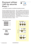
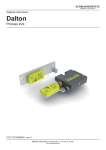
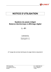
PLUTO
Safety-PLC
Operating instructions
Hardware
PlutoHardwareManual_Eng_v2B
1
www.jokabsafety.com
Table of contents:
1
General..................................................................................................................................3
2
Enclosure..............................................................................................................................4
3
Electrical installation ...........................................................................................................4
4
Inputs and outputs...............................................................................................................5
4.1
I0 – I7 Digital failsafe inputs. ......................................................................................... 5
4.2
IQ10 – IQ17 Digital failsafe inputs / Digital outputs (non failsafe) .............................. 6
4.2.1 Dynamic signals. ......................................................................................................... 6
4.2.2 Monitoring of muting indicator: ................................................................................. 6
4.3
Failsafe output................................................................................................................. 7
4.3.1 Q0 and Q1 relay output............................................................................................... 7
4.3.2 Q2 – Q3 solid state outputs........................................................................................ 7
5
Connection of inputs ...........................................................................................................8
5.1
Dynamic signals .............................................................................................................. 8
5.1.1 Connection of I 0 – I 7 ................................................................................................. 8
5.1.2 Connection of IQ 10 – IQ 17........................................................................................ 9
6
Connection of safety devices ...........................................................................................10
6.1
6.2
6.3
6.4
6.5
6.6
6.7
6.8
6.9
7
Dual channel systems................................................................................................... 10
Single channel systems................................................................................................ 11
Emergency stop ............................................................................................................ 11
Monitoring of external short circuit............................................................................. 12
Safety devices with transistor outputs ....................................................................... 13
Safety mats and safety edges ...................................................................................... 13
Two-hand control .......................................................................................................... 14
Illuminated push button function ................................................................................ 15
Monitoring of muting lamp ........................................................................................... 15
Connection of outputs .......................................................................................................16
7.1
Connection examples ................................................................................................... 16
8
Example of applications ....................................................................................................19
9
Bus communication...........................................................................................................20
9.1
9.2
Cabling ........................................................................................................................... 20
Response time over the bus ........................................................................................ 21
10
Identifier ..............................................................................................................................22
11
Programming......................................................................................................................22
12
Cleaning ..............................................................................................................................23
13
Technical data ....................................................................................................................23
14
Appendix - Message and fault code list ...........................................................................26
PlutoHardwareManual_Eng_v2B
2
www.jokabsafety.com
1 General
Pluto is a programmable safety system intended for safety applications where it is not accepted
that faults in the control system leads to loss of a safety function. To achieve this requirement
the system is designed with integral redundancy and monitoring. Unlike ordinary PLC systems,
Pluto utilizes two microprocessors, which both control and monitor each safety function for
correct operation. Each input to the system is separately connected to each processor, each
having their own memory and executing their own program. The processors continuously
compare the results with each other to ensure integrity of data.
Each safety output is connected to both processors and can not be set without both checking
that the logic conditions in the application program are fulfilled.
Each Pluto unit has connections for CAN-bus and can be interconnected with other Pluto units.
The degree of safety is the same over the bus as it is within each unit
Pluto is primarily designed for fulfilling the demands of the EU Machinery Directive (98/37/EG)
regarding safety of control systems and category 4 according to the harmonized standard EN
954-1. The system, however, can be used in other applications e.g. processing industry,
furnaces, etc. which have similar requirements.
PlutoHardwareManual_Eng_v2B
3
www.jokabsafety.com
2 Enclosure
Pluto is constructed in a 45mm wide box for snap mounting on a DIN-rail in control cabinets or
other suitable enclosures. External wiring is connected via screw terminals. To make it easy
and to avoid incorrect connection when a unit is exchanged, the connector blocks are
detachable so that individual wires do not have to be disconnected.
3 Electrical installation
The system is powered by 24V DC. For electrical safety reasons and in order to be able to
detect safety critical earth faults in single channel circuits, the 0V terminal must be connected
to protective bounding circuit. (see EN 60 204-1, 9.1.4).
The system is designed and tested for installation category II according to IEC 61010-1.
The system has internal over current protection (PTC) but should be protected by an external
fuse of maximum 6A. Cables and connected devices such as sensors, pushbuttons, selector
switches shall be isolated for 250V.
CH
CL
I1
I0
I6
I3
I2
I4 I5
IQ12 IQ14 IQ16
IQ13 IQ15 IQ17
IQ10
I7
Q0
ID
Q2
IQ11 Q3
Q1
0V
+24V
CH
CL
I1
I0
I3
I2
I4
IQ12 IQ14 IQ16
IQ13 IQ15 IQ17
Min. 5 mm space between units.
The terminal blocks are detachable in order to simplify replacement. Note that the power shall
be off during connection and disconnection
PlutoHardwareManual_Eng_v2B
4
www.jokabsafety.com
4 Inputs and outputs
In order to be as flexible as possible Pluto offers various combinations of different I/O: s.
4.1 I0 – I7
Digital failsafe inputs.
Each input is separately connected to both processors which, facilitating both single channel
and dual channel safety devices.
The inputs can be supplied by +24V or by the dynamic signal outputs A, B or C.
PlutoHardwareManual_Eng_v2B
5
www.jokabsafety.com
4.2 IQ10 – IQ17 Digital failsafe inputs / Digital outputs (non failsafe)
This group of 8 terminals provides 4 different functions. Each terminal is connected to both
processors and may therefore be used as a failsafe input.
Each terminal is also equipped with an output transistor which gives the user the option to
configure it as either a failsafe input or non failsafe output. The outputs are intended for
functions that do not require redundancy. E.g. indicators, status signals.
4.2.1
Dynamic signals.
3 of IQ10-IQ17 can be configured as dynamic outputs A, B or C for supplying inputs. When an
output is configured as dynamic, a unique pulse train is generated. As a safety input can be
configured just to accept this specific pulse train as the input condition, the system can detect
external short circuit conditions. (See separate description).
4.2.2
Monitoring of muting indicator:
IQ16-IQ17 has a function for monitoring of the output current when these terminals are used as
outputs. The function is mainly intended for monitoring of muting indicators according to EN
61 496-1. In some applications it is necessary to indicate that a safety device is muted. By
monitoring the current, the integrity of the filament of the light bulb is indirectly checked.
PlutoHardwareManual_Eng_v2B
6
www.jokabsafety.com
4.3 Failsafe output.
4.3.1
Q0 and Q1 relay output
Each potential free relay output is made individually ‘redundant’ by the use of two series
connected relay contacts controlled by each processor. A single output can be used to
individually control a safety function, however the outputs cannot detect short circuits in e.g.
connection cables. In addition to the output relays being controlled by separate processors the
power to the relay coils are generated by ‘charge’ pumps. (For description of function of
‘charge’ pump see section on failsafe solid state outputs).
4.3.2
Q2 – Q3 solid state outputs.
Each digital failsafe output is individually ‘redundant’ and can therefore be used to individually
control a safety function. The nominal output voltage is –24V DC. The negative potential is due
to the ‘charge’ pump principle used. The ‘charge’ pump is designed in such a way that the
output voltage is generated by a capacitor which is charged and discharged by two transistors.
The transistors switch alternately. One transistor switches to plus potential (+), charges the
capacitor and then switches off. The other transistor then switches on discharging the capacitor
to 0 Volts. During the discharge phase the capacitor ‘sucks’ current from the output making the
output a negative voltage. This design principle requires that all components work and change
state in the correct phase. A fault in any component leads to an immediate cessation of output
current generation.
An advantage of using a negative output potential is that it is not normally present in a control
system.Then the output is monitored, Pluto can detect short circuit between the output and a
foreign potential.
PlutoHardwareManual_Eng_v2B
7
www.jokabsafety.com
5 Connection of inputs
5.1 Dynamic signals
A maximum of three of the IQ10-IQ17 connections can be configured as dynamic outputs, and
be used for voltage supply of the input devices. If they are configured as dynamic, each of
them generates an unique pulse train as shown in the diagram bellow.
The system is intended for detection of different short circuits in external cabling, and dynamic
monitoring of sensors. It enables the connections of devices such as the Jokab “SPOT” light
beams, EDEN sensors etc. that inverts the input signal.
In the software a configuration of the inputs must be made to decide which kind of input signal
each input shall accept as logic ‘1’. Other signals that do not match with the configured signal
are regarded as ‘0’.
5.1.1
Connection of I 0 – I 7
I0-I7 can be connected to; A, B, C, A-inverse, B-inverse, C-inverse or +24V.
The diagram below shows possible connections and how they are configured in the software.
NOTE: The connections are only to show how devices can be electrically connected and are
not to be taken as connections for any specific applications.
Dyn A, B or C
IQ_
Configured as dynamic output
Example of software declaration:
! Q0.10, a_pulse
I_
Direct connection to dynamic output
Configured as dynamic input, not inverted
Example of software declaration:
! I0.0,a_pulse, non_inv
I_
I_
I_
I_
Connection to dynamic input with inversion
by either inverter or inverting safety device
Example of software declaration:
! I0.0,a_pulse
Direct connection to +24V or
safety device with transistor outputs.
Example of software declaration:
! I0.0,static
I_
PlutoHardwareManual_Eng_v2B
8
www.jokabsafety.com
5.1.2
Connection of IQ 10 – IQ 17
IQ10-IQ17 have some restrictions. If they are to be used as failsafe single channel inputs they
must be configured as dynamic; A, A-inverse, B, B-inverse, C or C-inverse. For some twochannel devices also +24V can be used.
IQ_
Dyn A, B or C
IQ_
OK
OK
OK
IQ16
IQ_
IQ15
Configured as dynamic output
The system does not accept
a direct connection between
a dynamic output and another IQ terminal.
A component or device, blocking
current from input must be applied
Example of declaration:
! I0.15,a_pulse
! I0.16,a_pulse,non_inv (with diode)
WARNING
Reset
OK
IQ_
IQ17
IQ 10-17 connected to +24V
does not fulfil category 4
as stand alone input
IQ 10-17 connected to +24V
fulfils the safety requirements
used for reset, start etc.
Example of declaration:
! I0.17,static
OK
IQ_
I
IQ 10-17 connected to +24V
fulfils category 4 by combination
with another dynamic input
NOTE:
The above connections are only to show how devices can be electrically connected and are
not to be taken as connections for any specific applications.
PlutoHardwareManual_Eng_v2B
9
www.jokabsafety.com
6 Connection of safety devices
6.1 Dual channel systems
Dyn C
Dyn B
Dyn A
The classic way of making a failsafe system is to use two-channel devices. The system offers
various possibilities for connection of such devices.
I0
IQ_
IQ_
I1
I2
I3
I4
I5
I6
I7
IQ_
Dual channel inputs with detection of external short circuits
PlutoHardwareManual_Eng_v2B
10
www.jokabsafety.com
6.2 Single channel systems
Instead of using two-channel systems some applications can be made failsafe by using the
principal of a dynamic single channel. By supplying electronic devices with dynamic signals a
fault in the electronics will lead to a static on or off state at the input which will be detected
immediately. By inverting the signal in or at the sensor, short circuits over the sensor are also
detected.
-
+
I_
IQ_
IQ_
IQ_
-
Dyn. C
Dyn. B
Dyn. A
+
I_
IQ_
I_
IQ_
IQ_
Note: Serial connection is legal, but a short circuit of an even number of sensors is not
detected.
A direct connection between two terminals of IQ10..17 is always detected. Detection of a short
circuit between an output of IQ10..17 and an input of I0..I7 is not detected.
See Technical data for number of serial connected sensors.
6.3 Emergency stop
When emergency stop functions often remain inactivated for long periods of time, the function
will not be monitored. It is therefore strongly recommended that emergency stop systems are
periodically, manually tested and that this forms part of the maintenance instructions for the
machine.
PlutoHardwareManual_Eng_v2B
11
www.jokabsafety.com
6.4 Monitoring of external short circuit
The system offers three main methods for avoiding that short circuits in input cabling leads to
loss of safety function. The drawing below illustrates the different methods by which emergency
stop buttons can be connected.
-
The first button has two NC contacts supplied by one dynamic signal and +24V. The inputs
are configured just to accept the expected signal and will therefore detect a short circuit
between the channels as well as to other foreign voltage.
-
The button in the middle has one NC and one NO contact supplied by +24V. The software
requires that the inputs operate in opposition to each other. A short circuit in the connecting
cable will have the effect that both inputs will at sometime during the cycle be ON, which
the system does not accept.
-
The last emergency stop button uses a short circuit proof single channel technique. A
dynamic signal is converted by an inverter mounted close to the contact. The input is
configured just to accept the inverted result of the supplied dynamic signal. A short circuit in
the connecting cable will result in an incorrect signal being presented to the input which will
not be accepted by the system.
PlutoHardwareManual_Eng_v2B
12
www.jokabsafety.com
6.5 Safety devices with transistor outputs
Certain safety devices on the market, i.e. light curtains, light beams, scanners, etc., are
designed with dual monitored safety 24V DC transistor outputs. These devices monitor the
output circuits by making short interruptions in the output signals.
Both channels can be connected to the system as static inputs, faults are detected by the
safety device, instead of by the Pluto system. But note that at least one of the inputs must
be one of I0-I7.
The short interruptions of the output signals are taken care of by the Pluto input filtering
system.
A list of devices tested in conjunction with Pluto is available from Jokab Safety.
IQ0.10
IQ0.12
OSSD2
OSSD1
I0.2
OSSD2
OSSD2
I0.1
OSSD1
OSSD1
I0.0
IQ0.13
Declaration in software (Pluto no:0) :
I0.0, static
I0.1, static
I0.2, static
I0.10, static
NOTE: At least one of the inputs must be one of I0-I7.
6.6 Safety mats and safety edges
Safety mats and safety edges must be supplied by two different dynamic signals and connected to
two inputs. By activation the two inputs will both get wrong input signal and give ‘0’ in the software
as result. The programming can be made in the same way as for other dual channel functions.
Examples of connections
PlutoHardwareManual_Eng_v2B
13
www.jokabsafety.com
6.7 Two-hand control
Two-hand control devices can be realized in many ways depending on the contact
configuration in the two-hand device and which Pluto inputs are used. Below are some
examples of solutions. All of the examples shown fulfil the requirements for type IIIC according
to EN 574.
Examples of two-hand control with NO/NC + NO/NC contacts
Examples of two-hand control with 2 NO + 2 NO contacts
PlutoHardwareManual_Eng_v2B
14
www.jokabsafety.com
6.8 Illuminated push button function
It is possible to connect both an indicator lamp and an input switch at the same time to
terminals IQ10-IQ17. e.g. illuminated push button. A diode must be connected locally to the
input device. The function is mainly intended for reset devices and reduces the number of IQ
terminals used.
Note that the output voltage is a square wave of 24 V amplitude and the effective voltage to the
indicator is reduced to a mean value of 75%. A filament bulb or LED designed for 24 VDC can
be used operation can be used.
6.9 Monitoring of muting lamp
The system can measure the current in output IQ16 and IQ17. The function is intended for
monitoring the current in a muting lamp, but other usage is not excluded. As the hardware for
measuring the current is not fully redundant the function must be used in a dynamic way if used
for safety functions. This means that the current must be read and evaluated both when the
output is switched on and off.
PlutoHardwareManual_Eng_v2B
15
www.jokabsafety.com
7 Connection of outputs
Below are examples of output connections that give different degrees of protection against
short circuits. When and where they can be used depends on the kind of machine application
(risk) and the electrical installation.
7.1 Connection examples
Output examples 1: Connection and monitoring of contactors.
A fault in a contactor will not lead to the loss of the safety function and is monitored then the
NC-contacts are connected to an input.
Note. Some short circuits from +24V and –24V can switch on both contactors and lead to loss
of the safety function.
The example connections can be used where the highest safety integrity level is not required
and the risk for short circuits is low or can be excluded e.g. inside a control cabinet. Example of
application is automatic machines where safety function is used by setting, adjustment etc.
PlutoHardwareManual_Eng_v2B
16
www.jokabsafety.com
Output examples 2: Contact expansion with Jokab Safety expansion relays and safety relay
The examples give the same degree of safety and have the same advantages and
disadvantages as output examples 1 and can be used for the same type of applications.
Output examples 3: Short circuit protected
Connection and monitoring of contactors with protection against short circuit, for applications
with very high demands on safety integrity level. (Category 4). In the example using output Q2
the conductor is protected with a shield connected to protective ground. Examples are
applications for safeguarding the operator of manual operated machines like presses and press
brakes.
PlutoHardwareManual_Eng_v2B
17
www.jokabsafety.com
Output example 4: Polarized safety relays
When using a safety relay for output expansion of output Q2 and Q3, the connection between
the Pluto output and the safety relay is failsafe against short circuit from foreign +24V. This
because it is operated by -24V and since the safety relay is polarized it cannot be switched on
by +24V. As long as a -24V potential does not exist in the cabinet (which is not normally the
case) the connection is failsafe.
PlutoHardwareManual_Eng_v2B
18
www.jokabsafety.com
8 Example of applications
PlutoHardwareManual_Eng_v2B
19
www.jokabsafety.com
9 Bus communication
Up to 32 Pluto units can be interconnected with CAN-bus. Communication is achieved by
connecting a twisted pair cable to the CH and CL terminals. When this connection is made the
Pluto units can read each others I/O.
When the bus connected each Pluto unit executes its own individual program and operates
independently, however it can read other units I/O.
An interruption of the bus connection results in the I/O in the unit with which communication is
lost, being regarded as a ‘0’ condition by other units on the bus. In this situation all units will
continue program execution with the consequences of the fault being dependant upon the
application program. For instance, if an emergency stop button connected to one unit is used
by another unit as a condition for setting an output, the output will switch off if communications
are lost. Outputs generated by I/O connected directly to a unit are not affected by interruption
of communications.
9.1 Cabling
The maximum length of CAN-bus cabling is dependant on the transmission speed. At the
default setting of 400 kbit/s the maximum total length is 150 meters. At each end of the bus a
termination resistor of 120 Ω must be installed. When a Pluto unit is working alone and no buscable is connected, it must still be equipped with a termination resistor.
The bus connection should be made with a twisted pair cable to the CH and CL terminals. Due
to EMC requirements bus cabling outside control cabinets must be shielded, one end of the
shield being connected to a central earthing point.
Cable lengths:
Data
Rate
Trunk Distance
100 kbit/s
125 kbit/s
200 kbit/s
250 kbit/s
400 kbit/s
500 kbit/s
800 kbit/s
1 Mbit/s
600 m
500m
300m
250m
150m
100m
60m
<20m
PlutoHardwareManual_Eng_v2B
Stub length
Units connected on a Stub must not have
termination resistors fitted.
Max single stub Accumulated stub length
25 m
120 m
20 m
100 m
13 m
70 m
10 m
50 m
6m
30 m
5m
25 m
3m
15 m
1m
5m
20
www.jokabsafety.com
9.2 Response time over the bus
As default the system works with the Baud rate set to 400 kbit/s and CAN-cycle to 20 ms. CANcycle 20 ms gives 10 ms extra response time for data over the bus (10-40 ms under fault
condition). The records under Technical data for response time over bus etc. are related to this.
To enable the use of longer cable lengths it is possible to change the baud rate to a lower
value, but care must be taken as the buss can be overloaded. To avoid this over load there are
two solutions: either to limit the amount of Pluto units connected on the bus or to increase the
Bus cycle time which also increases the response time.
Note that “Bus cycle time” is individually set for each Pluto unit which means that it is possible
to give variables of some Pluto units, better response times than others. It is also important to
note that if an input in one unit controls an output in another, it is regarding the response time
only relevant where the input is located. If the “Bus cycle time” in the unit with the output is
changed it has no influence on the response time.
The table below is a guideline for selection of bus parameters.
100 kb/s 125 kb/s 200 kb/s 250 kb/s 400 kb/s 500 kb/s 800 kb/s
Baud rate
Bus cycle time
10 ms
20 ms
30 ms
40 ms
3-4
6-8
12-18
12-23
4-6
10-14
15-21
20-30
8-10
20-32
20-32
28-32
12-14
22-32
25-32
30-32
18 - 25
32
32
32
25-32
32
32
32
32
32
32
32
Possible number of units connected to the bus.
NOTE: The prolongation of response time for I/O over the bus is equal with the Bus cycle time.
PlutoHardwareManual_Eng_v2B
21
www.jokabsafety.com
10 Identifier
The identifier is an external component that can be connected to the ‘ID’ and ‘OV’ terminals.
The circuit contains a unique ID-number that can be read by the system. In the PLC program
the identifier number can be declared which connects the program so that it will only work
together with the correct identifier. The use of identifier is voluntarily as long as a unit works
alone, but if an identifier is connected to the unit and the PLC program is declared to work
without, the program will not run.
The function gives a protection against a unit being exchanged by mistake. The identifier circuit
should be securely fastened to the physical location of the unit by e.g. tie it together with other
connection conductors.
Connection of identifier
When a number of Pluto-units are interconnected with the bus, identifiers are necessary.
The units are numbered 0…31. In the application program it is necessary to declare which
identifier number has to be connected to which Pluto unit (0…31). Example: !
id_pluto:01=023474526654
There are two types of identifier circuits available;
Pre-programmed: The number is programmed by the circuit manufacturer who guarantees that
two circuits with the same number do not exist.
Programmable: The number can be programmed by the user.
Programmable identifiers can for example be used where it is required to deliver units with the
same PLC program e.g. for a special machine or safety application.
11 Programming
The development of application programs (Pluto PLC program) is achieved using a standard
PC computer using a specially developed high level language. Communication between the PC
and the Pluto PLC is via a cordless Infrared (IR) link. This link facilitates program down loading
and monitoring of inputs, outputs, memory, timers, etc. with the PC ‘on line’.
See separate programming manual for further information.
PlutoHardwareManual_Eng_v2B
22
www.jokabsafety.com
12 Cleaning
The front plate can be cleaned by a dry dust rag. The front plate can also be removed for
cleaning or exchange.
13 Technical data
Supply
Nominal voltage
Voltage tolerance
Max interruption
24 V DC
-15%, +20%
20 ms
Power consumption at 24V
Unit consumption
Failsafe outputs
PLC outputs (non failsafe)
270 mA / 8,4 W
0 – 1.8 A / 0-43 W
0 – 2.5 A / 0-60 W
Recommended external fuse
Installation category:
6A
Category II according to IEC 61010-1
Failsafe inputs
I0 – I7
IQ10 – IQ17
Logic ‘1’
Logic ‘0’
+24V (for PNP sensors)
+24V (for PNP sensors) also configurable as
non-failsafe outputs.
> 12V
< 8V
Current at 24V
I0 - I3:
I4 - I7, IQ10 - IQ17:
12 mA
6 mA
Max. over voltage
Filter time (standard)
30 V continuously
5 – 10 ms, software
Safety output
Q2-Q3:
Output voltage tolerance:
Max. load / output:
Solid state, -24V DC
Supply voltage -1.5V at 800mA
800mA
Q0-Q1:
Max voltage
Max. load / output
Relay output
250 VAC
1.5 A
Outputs, non-failsafe
IQ10 - IQ17
Max load / output
Max totally load IQ10-IQ17
Transistor +24V, PNP open collector
(also configurable as failsafe inputs.)
800 mA
2.5 A
Current monitoring IQ16, IQ17
Range
0-1,0 A
Resolution
20 mA
PlutoHardwareManual_Eng_v2B
23
www.jokabsafety.com
Indication:
Input LED’s
1 per input (Green). Controlled by processor
Output LED’s
1 per output (Green). Controlled by processor
Indication of status and error
7 segment display
General
Enclosure
45 x 84 x 118 mm (w x h x d)
DIN-Rail mounting
Response time of dynamic A or static input (+24V):
Relay output, Q0-Q1:
< 20,5 ms + progr. execution time
Solid state output, Q2-Q3:
< 16,5 ms + progr. execution time
Solid state output, Q10-Q17: < 16,5 ms + progr. execution time
Response time of dynamic B or C inputs:
Relay output, Q0-Q1:
< 23 ms + progr. execution time
Solid state output, Q2-Q3:
< 19 ms + progr. execution time
Solid state output, Q10-Q17: < 19 ms + progr. execution time
Program execution time
approximately 10µs / instruction
Software setting ‘NoFilt’
Response times - 5 ms (5 ms less)
Extra response time over bus:
Normal condition
10 ms
Fault condition
10-40 ms
Q2-Q3 prolongation of response time under fault condition:
Detection time
Shortest detectable pulse
Ambient air temperature:
<10 ms
10 ms
-10°C - + 50°C
Temperature, transportation and storage:
- 25 - +55°C
Humidity:
EN 60 204-1: 50% at 40°C (ex 90% at 20°C)
Degree of protection:
Enclosure:
Terminals:
PlutoHardwareManual_Eng_v2B
IP 40 - IEC 60 529
IP 20 - IEC 60 529
24
www.jokabsafety.com
Connection of sensors
Maximum number of serial connected sensors:
Eden
10-12
Spot 35
3-4
Spot 10
2
Tina
10-12
Maximum number of serial connected sensors with 100m cable:
Eden
10-11
Spot 35
3
Spot 10
1
Tina
10-11
Maximum cable length for inputs using dynamic signals (depending on capasitance):
Example 10x0,75 mm²
approx. 1000 meter
PlutoHardwareManual_Eng_v2B
25
www.jokabsafety.com
14
Appendix - Message and fault code list
Status messages
No:
Description
Power up
Run mode for station number 0-9. (n = station number)
n
P n n Run mode for station number 10-31. (nn = station number)
L
Program load mode state.
Flashing ‘L’, ready for self programming (program found in other unit)
H
Program execution stopped from PC computer.
User faults
No:
Fault and possible reason.
E10
Dynamic output short circuited to foreign voltage.
E11
IQ_ for illuminated push button function. Missing diode
E12
Short circuit between two dynamic inputs
E13
Static output Q10…Q17 short circuited to 0V or
Q2-Q3 overloaded
E14
Static output Q10…Q17 short circuited to 24V.
E15
Power supply below 18V
E16
Power supply above 30V
E17
E18
CAN-bus fault.
(Short circuit, termination resistor, etc.)
E19
Other unit same station ID on Can-bus
E20
PLC-program not loaded
E21
PLC-program CRC-error
E22
Identifier problem. External identifier can not be read.
E23
Unmatched ID. Identifier doesn’t match declaration in
program.
E24
E25
E26
E27
Erroneous PLC-code. Invalid PLC-instructions.
For version A16. Non existing output used in program.
Baud rate conflict. Unit programmed for other baud rate
than current buss baud rate.
Wrong checksum for unit member in common program
PlutoHardwareManual_Eng_v2B
26
Reset action
Remedy of fault
Remedy of fault
Remedy of fault
Reset button, power off/on
Remedy of fault
Reset button, power off/on
Reset button, power off/on
Remedy of fault + reset button
Load of program
Re-load with valid PLC-program
Power off/on
Exchange of identifiers or redeclaration of identifier in
program.
Reload with valid code.
Reprogramming or reboot
Reprogramming or reboot
www.jokabsafety.com
I/O faults
No:
Fault and possible reason.
E 40 Error output Q0 - Q3.
E 41 Error output Q2 or Q3. Overload or foreign voltage.
E 42 Error output Q0 or Q1. (No answer from relay
monitoring.)
E43
Error output Q0 or Q1. (Self test of transistors)
E45
Analogue functions not calibrated
E49
Error calibration values, analogue functions
CPU faults
No:
Fault and possible reason.
E50
a/b twin input data diff
E51
a/b twin output data diff
E59
E60
E61
E62
E63
E64
E65
E66
E67
E68
E69
E70
E80
Power off/on
System must be calibrated
Recalibration
Reset action
Power off/on
Power off/on
Calibration analogue functions CRC fault
twin self test monitoring
Timer IRQ monitoring
Internal serial communication
Boot-flash CRC
OS-flash CRC
Plc-flash CRC
5 volt under/over voltage monitoring
CPU-test error
Ram-test error
Scan cycle time over run
System, sum of system and stack monitoring
Undefined self-test error
PlutoHardwareManual_Eng_v2B
Reset action
Remedy of fault + reset button.
Remedy of fault + reset button.
Remedy of fault + reset button.
27
Power off/on
Power off/on
Power off/on
Power off/on
Power off/on
Power off/on
Power off/on
Power off/on
Power off/on
Power off/on
Power off/on
Power off/on
Power off/on
www.jokabsafety.com