1
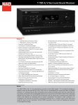
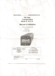
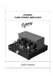
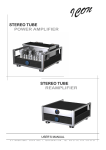
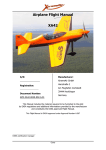
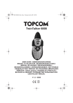
TRT800
ATC Transponder Mode A, A-C, S
P/N 800 ATC-(1XX)-(1XX)
Installation Manual
Document No.: 03.2101.010.12e
Revision 1.10
Datum: 18.05.2006
Filser Electronic GmbH Gewerbestraße 2 86875 Waal
phone: 08246 / 96 99-0 fax: 08246 / 10 49 web: www.filser.de
Installation Manual TRT800
Doc.-Nr: 03.2101.010.12e
Filser Electronic GmbH
Revision: 1.10
Page: 2 of 27
Installation Manual TRT800
Doc.-Nr: 03.2101.010.12e
Filser Electronic GmbH
Record of Revisions
Revision Date
Affected
Page(s)
05.04.06 all
18.05.06 all
Description of Change
1.0
1.10
initial issue
Para. 3.7, Plumbing installation, added
Record of Service Bulletins
ON RECEIPT OF SERVICE BULLETINS, INSERT SERVICE BULLETINS
IN THE MANUAL, AND ENTER DATE INSERTED AND INITIALS.
SB Number
Revision: 1.10
REV
No.
Date
Page: 3 of 27
Insertion
Date
Inserted by
Installation Manual TRT800
Doc.-Nr: 03.2101.010.12e
Filser Electronic GmbH
Table of Contents:
1. GENERAL INFORMATION ...............................................................5
1.1. EQUIPMENT DESCRIPTION .....................................................6
2. TECHNICAL CHARACTERISTICS ...................................................7
3. EQUIPMENT INSTALLATION ..........................................................9
3.1. UNPACKING AND INSPECTING EQUIPMENT .........................9
3.2. COOLING REQUIREMENTS FOR PANEL MOUNT...................9
3.3. MUTUAL SUPPRESSION PULSES ...........................................9
3.4. MOUNTING INSTALLATION .................................................... 10
3.5. ELECTRICAL CONNECTIONS................................................. 10
3.6. ANTENNA INSTALLATION ...................................................... 10
3.6.1. Location Considerations...................................................... 11
3.6.2. Blade antenna TRT-ANT-A ................................................. 11
3.6.3. Antenna Cable Installation .................................................. 12
3.7. PLUMBING INSTALLATION..................................................... 13
3.8. AIRCRAFT Address Programming............................................ 14
3.8.1. ICAO 24 Bit Aircraft Address............................................... 14
3.8.2. ICAO 24 Bit Aircraft Address Entry Page ............................ 15
3.8.3. Guidance for Entering the Flight Identification..................... 17
3.8.4. Squitter Mode Entry Page ................................................... 18
3.9. TEST MODE Page.................................................................... 20
3.9.1. List of Error Codes .............................................................. 20
4. AIRCRAFT INTERFACE................................................................. 21
4.1. General ..................................................................................... 21
4.2. COMM-A................................................................................... 21
4.3. COMM-B................................................................................... 22
4.3.1. Close out for COMM-B........................................................ 22
4.4. Compact Position Reporting (CPR)........................................... 23
5. POST INSTALLATION CHECKOUT ............................................... 23
6. Interconnect diagrams..................................................................... 24
7. Dimensions of the TRT800.............................................................. 26
Revision: 1.10
Page: 4 of 27
Installation Manual TRT800
Doc.-Nr: 03.2101.010.12e
Filser Electronic GmbH
1. GENERAL INFORMATION
Mode S has several advantages over the current ATCRBS (Mode A/C)
transponder standard. It offers much more efficient utilization of the
existing SSR spectrum. As airspace densities continue to increase, the
ability for ground stations (and TCAS) to accomplish their required
surveillance of the airspace is being threatened due to saturation of the
SSR spectrum.
This manual describes the physical, mechanical, and electrical
characteristics and the installation requirements for the TRT800 Mode S
Transponder.
It contains suggestions and factors to consider installing the TRT800.
Close adherence to these suggestions will assure more satisfactory
performance from the equipment.
Information relative to operating procedures are found in the TRT800
Operation Manual (Document Number 03.2101.010.11).
Safety symbols:
This manual uses the following symbols to point out specific information:
Warning
Identifies an instruction which, if not followed, may cause
serious injury including the possibility of death.
Caution
Denotes an instruction which, if not followed, may severely
damage the equipment or other component.
Note
Indicates supplementary information which may be needed
to fully complete or understand an instruction.
Revision: 1.10
Page: 5 of 27
Installation Manual TRT800
Doc.-Nr: 03.2101.010.12e
Filser Electronic GmbH
1.1.
EQUIPMENT DESCRIPTION
The TRT800 is a panel mounted Non-Diversity Mode S Transponder and
employs one antenna, to be mounted on the bottom of the aircraft.
The design meets EUROCAE ED-73B, ICAO Annex10 Amendment 77,
CS-ETSO-2C112a, EUROCAE ED-73B as well as AIC IFR 6/03, AIC
IFR 7/03 and AIC VFR 9/03 from the DFS and is certified to these
specifications.
The TRT800 transponder is a radio transmitter and receiver that
operates on radar frequencies, receiving ground radar interrogations at
1030 MHz and transmitting a coded response of pulses to ground-based
radar on a frequency of 1090 MHz. The TRT800 is equipped with IDENT
capability that activates the Special Position Identification (SPI) pulse for
18 seconds.
The TRT800 replies to ATCRBS Mode A, Mode C and required formats
for Mode S interrogation. It also transmits the acquisition and extended
SQUITTER depending on pre-selection and provided aircraft data. Mode
A replies consist of any one of 4,096 codes, which differ in the position
and number of pulses transmitted. Mode C replies include framing pulses
and encoded altitude. Mode S interrogations are selective. The Mode S
transponders can respond to a single directed interrogation from the
ground station or another aircraft.
The TRT800 is a Level 2es Class 2 transponder, providing downlink of
aircraft information. Ground stations can interrogate Mode S
Transponders individually using a ICAO 24-bit Mode S address, which is
unique to the particular aircraft. In addition, ground stations may
interrogate a TRT800 for its Transponder data capability and the
aircraft's Flight ID, which may be the registration number or other call
sign.
In addition to displaying the code, reply symbol and mode of operation,
the TRT800 screen displays pressure altitude, depending on equipment
configuration selection. The unit also features a temperature
compensated high precision piezoresistive pressure sensor and a RS232 I/O data port.
Revision: 1.10
Page: 6 of 27
Installation Manual TRT800
Doc.-Nr: 03.2101.010.12e
Filser Electronic GmbH
2. TECHNICAL CHARACTERISTICS
Compliance:
CS-ETSO-2C112a
Physical Dimensions:
TRT800
Height:
2,6 in 6,6 cm
Width:
Length:
Weight:
2,6 in 6,6 cm
7,1 in 18 cm
1,5 Ibs 0,7kg
Applicable Documents
ICAO Annex 10 Amendment 77,CS-ETSO-2C112a,
TSO-C112 EUROCAE ED-73B, EUROCAE ED-26,
RTCA DO-160D, RTCA DO-178B, AIC IFR 6/03,
AIC IFR 7/03, AIC VFR 9/03
Mounting
TRT800:
Operating Temperature
Range:
Altitude Range
Panel 57mm
-20 °C to +55 °C
short-time +70°C
15,000 ft
Cooling:
Vibration:
Shock:
Power Input
TRT800:
No forced-air cooling required, but recommended.
DO160D, Cat. S, Vibration Curve M
Rigid mounting 6 G operational, 20 G crash safety.
Receiver Characteristics:
Sensitivity
The minimum triggering level (MTL) is defined as the
minimum input power level that results in a 90%
reply ratio if the interrogation has nominal pulse
characteristics.
A. The MTL for ATCRBS and ATCRBS/Mode S AllCall interrogations will be -74 dBm ±3 dB.
B. The MTL for Mode S interrogations will be 74dBm ± 3 dB.
Revision: 1.10
between 10 and 16 Vdc
typical: 0.40 A @ 13.8 Vdc
maximal: 0.7A @ 13.8 Vdc
10 Watts (max)
Page: 7 of 27
Installation Manual TRT800
Doc.-Nr: 03.2101.010.12e
Filser Electronic GmbH
Transmitter
Characteristics:
Reply Transmission
Frequency:
RF Peak Power Output:
Squitter:
1090 ± 1 MHz.
at least 18,5dBW (71 watts) peak power minimum at
the terminals of the transponder antenna.
Random intervals uniformly distributed over the
range from 0.8 thru 1.2 seconds, full self verification
of data and occurrence
Mode S Elementary Surveillance
24-bit aircraft address
Mode S Address unique to each aircraft as assigned
by appropriate state authorities
Automatic reporting of
aircraft identity
Capability Report
Flight ID: Flight Plan call sign or aircraft registration
marking
Reports the available data and means by which the
transponder can report.
Pressure Altitude
Up to 15.000 ft in 100 ft increments
Flight Status
Airborne / on-ground
Mode S Enhanced Surveillance
Level 2 (es)
Revision: 1.10
Comm A / Comm B 56/112 Bit Messages
Page: 8 of 27
Installation Manual TRT800
Doc.-Nr: 03.2101.010.12e
Filser Electronic GmbH
3. EQUIPMENT INSTALLATION
The TRT800 installation will conform to standards designated by the
customer, installing agency, and existing conditions as to the unit
location and type of installation. However, the following suggestions
should be considered before installing the TRT800. The installing agency
will supply and fabricate all external cables. Interconnect diagrams are
included at the end of this manual.
Transponder, AC Address Adapter, all cable and antennae should be
installed as per FAA Advisory Circular AC43.13-2A Methods and
Guidelines and the appropriate manufacturers instructions.
3.1.
UNPACKING AND INSPECTING EQUIPMENT
Unpack the equipment carefully and inspect each item for evidence of
damage incurred during shipment. If a damage claim has to be filed,
save the shipping container and all packing materials to substantiate
your claim. The claim should be filed with the transportation company as
soon as possible. The shipping container and packing material should be
saved in any case in the event that storage or reshipment of the
equipment is necessary.
3.2.
COOLING REQUIREMENTS FOR PANEL MOUNT
The most important contribution to improved reliability of avionics
equipment is to limit the maximum operating temperature of each unit.
While modern designs consume less total energy, the heat dissipated
per unit volume (Watts/cubic inch) remains much the same due to
contemporary high density packaging techniques. While each individual
unit may or may not require forced air cooling, the combined heat
generated by several units operating in a typical panel or rack can
significantly degrade the reliability of the equipment if provisions for
adequate cooling are not incorporated in the initial installation.
3.3.
MUTUAL SUPPRESSION PULSES
Other equipment on board the aircraft may transmit in the same
frequency band as the transponder, such as DME or another interfering
units. Mutual suppression is a synchronous pulse that is sent to the other
equipment to suppress transmission of a competing transmitter for the
duration of the pulse train transmission. The transponder transmission
may be suppressed by an external source and other equipment on board
may be suppressed by the transponder. This feature is designed to limit
mutual interference.
Revision: 1.10
Page: 9 of 27
Installation Manual TRT800
Doc.-Nr: 03.2101.010.12e
Filser Electronic GmbH
3.4.
MOUNTING INSTALLATION
A. The TRT800 is mounted rigidly in the aircraft panel. Select a position
in the panel that is not too close to any high external heat source.
Remember to allow adequate space for installation of cables and
connectors. Avoid sharp bends and placing the cables too near the
aircraft control cables.
B. Standard 57mm cut-out is required for panel mounting the TRT800.
C. It is fastened by four 6mm special cavity screws leading through the 4
axis of the rotating knobs. Before installation the knops and the cavity
screws have to be removed.
3.5.
ELECTRICAL CONNECTIONS
All electrical connections, except for the antenna, are made through a
single, 15 pin D-sub miniature connector. Use only the AC Address
Adapter EM800 as it contains the EEPROM with the memorized ICAO
Aircraft code.
The AC Address Adapters EM800 listed below are available:
Filser P/N TRT800EM
Filser P/N TRT800EMSS
AC Address Adapter EM800 with power cable. This is
the standard connector supplied with each unit.
AC Address Adapter EM800 with power cable and
interface connector
The TRT800 has to be protected by an external slow blow fuse of 2
Ampere.
3.6.
ANTENNA INSTALLATION
Particular attention must be paid to the proper antenna installation on the
aircraft so that the specified minimum radiation is ensured. The radiation
pattern needs to be verified per aircraft type. Credit can be taken from
the approval of a similar type.
Normally the antenna will be mounted at the bottom of the aircraft.
However sufficient field strength should also be available above the light
aviation vehicle so that proper detection by ACAS equipped other aircraft
is ensured.
The electrical interference between the antenna and any other
antenna/equipment must be taken into account in such a way that no
reduction of the performance of any other system will occur.
Particular care should be taken to ensure that the interference on the
TRT800 antenna subsystem caused by static electricity is minimized.
Revision: 1.10
Page: 10 of 27
Installation Manual TRT800
Doc.-Nr: 03.2101.010.12e
Filser Electronic GmbH
Electrical connections to antenna shall be protected to avoid loss of
efficiency as a result of the presence of liquids or moisture.
All antenna feeders shall be installed so as to ensure that a minimum of
radio frequency energy is radiated inside the aircraft. Especially RF
hazard exposure to persons on board the aircraft should be minimized by
appropriate precautions.
The antenna type chosen shall be compatible with the vehicle on which it
is used and the location where it is mounted.
Warning
Radiation Hazards
In order to avoid the possibility of human body damage (e.g.
to eyes) and/or ignition of combustible materials by radiated
energy, a safe distance to the installed antenna must be
ensured by adequate installation provisions.
•
•
•
•
3.6.1. Location Considerations
The antenna should be mounted on the underside of the aircraft
and in a vertical position when the aircraft is in level flight
Avoid mounting the antenna within three feet of the ADF sense
antenna or any other communication antenna and six feet from the
DME antenna.
If the antenna is being installed on a composite aircraft, ground
planes must be added or a symmetrical Antenna can be installed.
the antenna should be installed according to the antenna
manufacturer’s instructions.
3.6.2. Blade antenna TRT-ANT-A
The blade antenna is a normal ground plane antenna for installation in
metal aircrafts or where a ground plane (metal plate, min. size 30x30 cm)
can be installed.
Other antenna will be offered by Filser Electronic GmbH when they are
available. For mounting on aircraft made of composites the ground plane
should be as large as possible but not less than 30 x 30 cm for
satisfactory performance. If in doubt please contact the aircraft
manufacturer.
Revision: 1.10
Page: 11 of 27
Installation Manual TRT800
Doc.-Nr: 03.2101.010.12e
Filser Electronic GmbH
3.6.3. Antenna Cable Installation
When routing antenna cables, observe the following precautions:
• All cable routing should be kept as short as possible and as direct
as possible.
• Avoid sharp bends.
• Avoid routing cables near power sources (e.g., 400 Hz generators,
trim motors, etc.), ignition coil or near power for fluorescent lighting.
• Avoid routing cable near ADF antenna cable (allow at least a 12inch separation).
A special cable type (CELLFOIL, or AIRCELL) has low attenuation at
1090 MHz but it is not very resistant against mechanical stress like sharp
bends. Therefore at mounting positions in rudders it requires a careful
design.
Revision: 1.10
Page: 12 of 27
Installation Manual TRT800
Doc.-Nr: 03.2101.010.12e
Filser Electronic GmbH
The following table lists examples of the recommended antenna cable
and the type of cable to be used for specific lengths of cable. Any cable
meeting specifications is acceptable for the installation.
FILSER PART NUMBER
P/N TRT800EM
P/N TRT800EMSS
Install kit 1 optional
P/N TRKABEL2
Install kit 2 optional
P/N TRKABEL3
Install kit 3 optional
P/N TRKABEL4
Antenna kit 1 optional
P/N CI-105
DESCRIPTION
AC Address Adapter EM800 with power cable.This is
the standard connector supplied with each unit.
AC Address Adapter EM800 with power cable and
interface connector
Cable, Coax TNC
2,5 m, 8,2ft, 0,4dB loss
Cable, Coax TNC
4,0 m, 13,2ft, 0,62dB loss
Cable, Coax TNC
6,5 m, 21,3ft, 1,0dB loss
Transponder/ DME antenna TSO C66b,C74c CI105
Comant Industries Inc., height 3.25”, weight 0.2 lb
Caution
The maximum coaxial cable attenuation between
Transponder and Antenna at 1090 MHz must not
exceed 1.5 dB.
3.7.
PLUMBING INSTALLATION
Install an approved soft tubing fitting the 5mm static port at the back side of the
transponder.
When all connections are made, secure plumbing with appropriate clamps.
Revision: 1.10
Page: 13 of 27
Installation Manual TRT800
Doc.-Nr: 03.2101.010.12e
Filser Electronic GmbH
3.8.
AIRCRAFT Address Programming
3.8.1. ICAO 24 Bit Aircraft Address
All Mode S transponders are identified with their unique, 24 bit, ICAO
Mode S Aircraft Address. This address is assigned to each aircraft
operating a Mode S transponder by the governing regulatory agency.
Furthermore the Mode S transponder has the capability to store a Flight
Identification( FID, in most countries the tail number of the aircraft).
A Mode S transponder shall include means to ensure that it is using the
ICAO 24 bit aircraft address allocated to the airframe on which it is
installed in all applicable Mode S transactions.
The ICAO 24 bit aircraft address must be correct at all times, as it is
used for the technical addressing of the aircraft. Any duplication of an
address in a particular airspace would put the data surveillance and
integrity figures of Mode S in jeopardy.
Note
Any intervention of the user may accidentally result in a
wrong ICAO 24 bit address and may therefore cause serious
technical problems in ACAS or ATC systems.
The transponder must include means to input and store the aircraft
address (AA) and the flight identification (FID). To meet this
specifications the TRT800 has an external memory (EEPROM) inside
the connector housing of the cable set, which will be delivered with the
unit.
This cable with memory will remain installed in the aircraft after the unit
is removed to insure that the ICAO 24 bit aircraft address is fixed to the
aircraft.
Revision: 1.10
Page: 14 of 27
Installation Manual TRT800
Doc.-Nr: 03.2101.010.12e
Filser Electronic GmbH
3.8.2. ICAO 24 Bit Aircraft Address Entry Page
When the unit is turned on for the first time, or an invalid address is
recognized, the unit will prompt the user to enter a valid aircraft address
(ID).
Without entering an ID the Transponder will not have any Mode S
functions but will still be in Mode A/C operative.
Note
Only approved maintenance shop have the personal and
equipment to insure that the programming of the aircraft
address/category/squitter and the installation are performed
and tested properly.
A. Case of no valid ICAO 24 Bit Aircraft Address in memory (factory
setting)
1. Switch the unit to “ON” condition.
The display will show
“CRADLE OFF-- OUT OF ORDER”
Press and hold the “FID” button and a number on the right top
side of the display starts counting up 1, 2, 3… Release the button
at 47.
2. On the display the lower line shows a long number as described in
the picture below. The first 6 digits are the aircraft address (ICAO
24 bit AA in HEX-format, received from your local aviation
authority) followed by 2 digits for the aircraft category (e.g. 19 for
gliders) and then 7 digits for the Flight Identification (FID).
Caution
The ICAO Flight Plan specifies only 7 characters as Flight
Identification. Filser reserves 8 characters as stated in ED73B for further expansion of the flight plan. The user shall
only program 7 characters for FID. Please refer to chapter
3.6.3 for guiding instructions.
Revision: 1.10
Page: 15 of 27
Installation Manual TRT800
Doc.-Nr: 03.2101.010.12e
Filser Electronic GmbH
3. Insert the valid ICAO aircraft address in HEX format, the aircraft
category and the Flight Identification ( which is usually the aircrafts
tail-sign, see chapter 3.6.3) by using
• the lower right rotating knob (..X. ) as a cursor “^” position
• the lower left knob (.X..) to change the contents of the
selected position (0-9 and A-F).
4. Confirm the entered code by pressing the “MODE” button.
5. The new code is now activated and stored to the external memory.
Aircraft address
= 6 digits
Aircraft Category
= 2 digits
e.g. 19 for gliders
1^C4E619DEHUPDC
Flight
Identification=
7 digits
The definition of the aircraft categories are:
1A=Balloon & airship
11= vehicle
1B=Paraglider
19=Glider
1C=UL,
12=emergency
27=Helicopter,
vehicle
1E=Drone
21=light aircraft up
to 7031 kg (< 15.500
lbs)
Revision: 1.10
Page: 16 of 27
Installation Manual TRT800
Doc.-Nr: 03.2101.010.12e
Filser Electronic GmbH
B. Modification of an existing ICAO 24 Bit Aircraft Address
1. press the MODE button until STBY is displayed
2. go to step 3 of the procedure above and insert the aircraft address.
C. Modification of an existing Flight Identification
1. press the MODE button until STBY is displayed
2. go to step 3 of the procedure above and insert the Flight
Identification (please refer to chapter 3.6.3 for guidance).
The contents of the aircraft code line will be stored into the external
aircraft connector (EEPROM memory).
3.8.3. Guidance for Entering the Flight Identification
ICAO Document 8168-OPS/611 Volume I (Procedures for Air Navigation
Services) requires that flight crew of aircraft equipped with Mode S shall
set the aircraft identification, commonly called Flight-ID, into the
transponder. That is necessary to ensure that the correlation between
flight plan and radar data will work automatically. ATC providers have
reported that their radar has seen many aircraft with an incorrect FlightID.
The Flight-ID setting is required to correspond to the aircraft identification
that has been (correctly!) specified at item 7 of the ICAO flight plan and
consists of no more than seven charters. If the aircraft identification
consists of less than seven characters, it shall be entered left-aligned
with no zeros, dashes or spaces added.
For an aircraft using a company call sign, the Flight-ID consists of the
ICAO three-letter designator for the aircraft operator, followed by an
identification code, e.g. KLM511, BAW213, JTR25.
If no company call sign is used or even no flight plan is filed, the default
Flight-ID to be set consists of the registration marking of the aircraft, e.g.
GXXXX, 4XBCD, DEABC, again with no additional zeros, dashes or
spaces. Do not use dashes even if they are included in the registration
marking painted on the aircraft (tail number).
Revision: 1.10
Page: 17 of 27
Installation Manual TRT800
Doc.-Nr: 03.2101.010.12e
Filser Electronic GmbH
3.8.4. Squitter Mode Entry Page
After the aircraft Address is entered press the MODE button go to the
next step.
The next display appears to setup the squitter capability.
________
The squitter definitions are:
AE1
acquisition + extended Squitter (for position + aircraft
identification )
AE2
acquisition + extended Squitter (for position + velocity +
aircraft identification)
The minimum mandatory Squitter capability is the AE1. If there is a
interface for a GPS position report the AE1 should be selected. In case
of a high level installation providing all the aircraft data (needs ARINC
adapter) various velocities, turn rate, vertical rate ect. AE2 can be
selected.
Revision: 1.10
Page: 18 of 27
Installation Manual TRT800
Doc.-Nr: 03.2101.010.12e
Filser Electronic GmbH
To leave the programming mode and to save the settings press the
MODE button again. The contents of all this codes will be stored into the
external (cradle-EEPROM) memory.
Caution
After the installation is complete, a certified maintenance
shop must verify proper operation of the transponder by
testing in accordance with Appendix F to 14 CFR Part 43 –
ATC
Transponder
Tests
and
Inspections.
The most important factor in the transponder configuration is
the checking of the Mode S address. Verify proper operation
of the transponder during a flight test under VFR conditions.
If no valid ICAO aircraft address is programmed to the unit or
if the memory is inoperative the transponder will inhibit the
S-Mode functions. Only A/C mode function will be available.
Revision: 1.10
Page: 19 of 27
Installation Manual TRT800
Doc.-Nr: 03.2101.010.12e
Filser Electronic GmbH
3.9.
TEST MODE Page
To enable the TEST MODE Page press the “MODE” button until STBY is
displayed in the Mode Status.
While pressing the button “FID” (upper right) a number will start to count
up once per second. The Unit will enable the TEST MODE when number
7 appears and the button is released.
In this mode all transponder functions are still active except that errors
will not result in changing the mode to STBY. The error codes for
receiver signal quality (Sn) will now be displayed. This mode is used for
troubleshooting.
Squitter flag:
a= aquisition, p=position
v=velocity, i=identity
Reply flag
A=allcal, C=A/C
R=S-mode
If dot
Aircraft interface on
P= ADS-B-Position input,
A= Interface and init COM-B
E= Event driven squitter
T= TRA (BDS 07)
ON
OFF
FID
...X
X...
A. Si
ACS
.X..
P
MODE
TM
24
Fl0100
G
IDENT
Mode Status:
STBY
A-S
ACS
FPG
MTL
ANT
DC
TRX
PLL
3.9.1. List of Error Codes
Dialogue error to FPGA
Problem with minimum trigger level
Mismatch at antenna
Warning for low voltage
To low output power
Receiver frequency error
Revision: 1.10
Page: 20 of 27
..X.
Testmode active
FPGA-Error code
Flight Level
Status GND/FLIGHT
Installation Manual TRT800
Doc.-Nr: 03.2101.010.12e
Filser Electronic GmbH
4. AIRCRAFT INTERFACE
4.1.
General
The TRT800 provides a serial RS232 interface data transfer to and from
the other aircraft equipment. This can be:
• A continuous position report generated by e.g. a GPS system to
be broadcasted by extended squitter (in BDS 0,5; 0,6) and in
downlink format DF 20 and 21.
• COMM-A to receive e.g. the Traffic Information Service (TIS).
• COMM-B for broadcasting a ground-initiated or air-initiated
message.
• COMM-B to send an addressed air-initiated message to a specific
ground station.
For COMM-A the data rate needs to be relatively high for a serial
interface. Therefore the rate for this interface is set to 38400 bd. The
data output comes in an binary format. For the data input the NMEA
standard IEC 61162-1 (using sub format RMC) is used to be compatible
to the most of the GPS interfaces, but instead of the 4800bd the
38400bd is required.
To convert the data rate from any position source (e.g. GPS) from the
low rate to the high and for distribution and conversion of the received
data (TIS) an external unit is required. This unit can also be a converter
to the ARINC standard.
4.2.
COMM-A
Comm-A is the transmission of information from the ground to the
aircraft.
Each message (per interrogation) contains 7 byte of information.
The transponder will direct the content of received Comm-A data to the
RS232- interface with a data rate of 38400 bd which is required in case
of the maximum of 50 interrogations per sec.
The data format (all in hex notation) is:
SYNC, CTR, UF, message 4 or 10 bytes.
SYNC are two byte fixed set to FF11 for synchronization.
CTR is a continuous counter which increments with every transfer.
UF indicates the received uplink format where (in hex notation)
AX = UF20/21 ,
2X = UF4/5,
X=(1,,,F)
In case of UF20/21 the remaining data length is 10 bytes, for UF4/5 it is
3 bytes.
Revision: 1.10
Page: 21 of 27
Installation Manual TRT800
Doc.-Nr: 03.2101.010.12e
Filser Electronic GmbH
4.3.
COMM-B
Comm-B is the transmission of information from the aircraft to the
ground. A message can be ground-initiated (GICB) or air-initiated
(AICB). The AICB can be a broadcast message or it can be a
Nonselective, Multiside or , Multisite Directed Comm-B transmissions.
The data format to be received on the serial interface is similar to the
NMEA-position data:
$AVCBC,+1+7+3 byte:
( IIS-byte + 7 byte + * + 2chks )
$AVCBC start for the COMM-B format in ASCII characters.
Also the last byte before the two byte checksum is a ASCII “*”.
All data bytes are binary.
The first data byte is the IIS-address byte to select a ground station in
case of a Multisite Directed Comm-B transmissions.
For all other transmissions it must be zero.
The next 7 byte are for the user data.
The remaining 3 byte (*, checksum) are required to close the
transmission as defined in NMEA.
4.3.1. Close out for COMM-B
This is a data string for acknowledging the end of a COMM-B activity to
the aircraft avionic.
The data format is similar to a COMM-A message but using a different
sync code (hex notation) which is FF12.
The message is only one byte.
SYNC, Bstatus.
The meaning of COMM-B statusbyte (Bstatus) is:
• Bit 7 is set = the Interrogator has requested CommB reservation.
• Bit 6 is set = the interrogator has captured Comm-B data.
• Bit 5 is set = the interrogator has required closeout.
• Bit 5 to 7 all 0 = End of transfer or timer run out.
• Bit 4 to bit 0 = Interrogator identifier.
The byte Bstatus is for control only. After an initialization by AICB or
GICB the hand shake sequence runs automatically without requirements
from the external data converter.
Revision: 1.10
Page: 22 of 27
Installation Manual TRT800
Doc.-Nr: 03.2101.010.12e
Filser Electronic GmbH
4.4.
Compact Position Reporting (CPR)
For the encoding of the CPR (Compact Position Reporting) the following
documentations has been used:
ICAO-Do9688-AN952; RTCA DO-260A; ECC-Task AT58.
5. POST INSTALLATION CHECKOUT
Refer to operation manual for the following checks.
After the installation is complete, verify proper operation of the
transponder by testing in accordance with Appendix F to 14 CFR Part 43
– ATC Transponder Tests and Inspections.
Perhaps the most important factor in the TRT800 transponder
configuration and checkout are the Mode S aircraft address (AA) and
flight identification (FID).
Be sure to check all aircraft control movements before flight is attempted
to insure that the wiring harness does not touch any moving parts.
Verify proper operation of the transponder during a flight test under VFR
conditions. If the unit detects an internal failure mode the failure code is
displayed on the screen.
Revision: 1.10
Page: 23 of 27
Installation Manual TRT800
Doc.-Nr: 03.2101.010.12e
Filser Electronic GmbH
6. Interconnect diagrams
P1
T
R
T
8
0
0
/
8
0
0
A
/
H
1
2
3
4
5
6
7
8
9
10
11
12
13
14
15
Power GND
Spare
internal use+)
internal use+)
Serial interface out COMM-A (TX-RS232)
Suppression input
Spare
+ DC Power
Power GND
internal use+)
internal use+)
Serial interface in COMM-B (RX-RS232)
Suppression – I/O
Light**)
“On Ground” switch *)
TNC Connector
XPDR Antenna
+) for memory inside Connector
**) “Light” Connect to GND for light OFF
Connect to +DC Power, dimmer or lighting switch for light ON.
*) “On Ground” switch: When the aircraft is in “On Ground” condition switch Pin 15
to Pin 1 (or Pin 9), else leave Pin 15 un-switched open.
Revision: 1.10
Page: 24 of 27
Installation Manual TRT800
Doc.-Nr: 03.2101.010.12e
Filser Electronic GmbH
TRT800 EMSS
Revision: 1.10
Page: 25 of 27
Installation Manual TRT800
Doc.-Nr: 03.2101.010.12e
Filser Electronic GmbH
7. Dimensions of the TRT800
1
Revision: 1.10
Page: 26 of 27
Installation Manual TRT800
Doc.-Nr: 03.2101.010.12e
Filser Electronic GmbH
Revision: 1.10
Page: 27 of 27