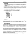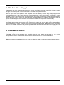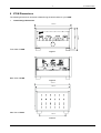
1
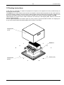
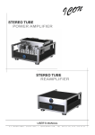
STEREO
TUBE POWER AMPLIFIER
USER’S MANUAL
S . T . I N N O V A T O R S
-
S O F I A
1 5 0 5 ,
1 ,
T Z A R I C H I N A
S T R . ,
T E L .
8 7 0 - 2 1 - 5 6 ,
F A X .
9 7 3 - 3 7 - 2 7
2
S.T.INNOVATORS
Table of Contents
IMPORTANT SAFETY INSTRUCTIONS!.................................................................................................3
1
General Notes...................................................................................................................................5
2
Introduction .......................................................................................................................................5
3
Why Vacuum Tubes?........................................................................................................................5
4
Why Pulse Power Supply?................................................................................................................6
5
Performance Features ......................................................................................................................6
6
ICON Dimensions .............................................................................................................................7
•
•
7
Closed Design Dimensions ...........................................................................................................................7
Open Design Dimensions..............................................................................................................................8
Installation of Tubes..........................................................................................................................9
•
•
•
•
•
8
9
10
11
12
•
•
13
14
15
General Notes ...............................................................................................................................................9
Power Output Tubes ...................................................................................................................................11
Driver Tubes ................................................................................................................................................12
Indicator Tubes............................................................................................................................................12
Small Input Tubes .......................................................................................................................................12
Location and Ventilation..................................................................................................................13
Tubes, Connections and Switches location ....................................................................................14
How to Connect for Stereo..........................................................................................................15
How to Connect for Mono Parallel ..............................................................................................17
How to Operate the ICON ...........................................................................................................19
Power On, Stand-by and Off .......................................................................................................................19
Input Switch .................................................................................................................................................19
Setting the Tubes Bias ................................................................................................................20
Specifications ..............................................................................................................................21
Packing Instructions ....................................................................................................................22
ICON rev.mar.2005
S.T.INNOVATORS
3
IMPORTANT SAFETY INSTRUCTIONS!
PLEASE READ THEM BEFORE OPERATING THIS EQUIPMENT.
The lightning flash with arrowhead,
within an equilateral triangle, is
intended to alert the user to the
presence of uninsulated "dangerous
voltage" within the product's enclosure
that may be of sufficient magnitude to
constitute a risk of electric shock to
persons.
CAUTION
RISK OF ELECTRIC SHOCK
DO NOT OPEN
AVIS RISQUE DE CHOC ELECTRIQUE - NE PAS OUVRIR.
WARNING - TO REDUCE RISK OF
FIRE OR ELECTRICAL SHOCK, DO
NOT EXPOSE THIS EQUIPMENT TO
RAIN OR MOISTURE.
The exclamation point within an equilateral triangle is intended to alert the
user to the presence of important
operating and maintenance (servicing)
instructions in the literature accompanying the appliance.
NO USER-SERVICEABLE PARTS
INSIDE. REFER SERVICING TO
QUALIFIED PERSONNEL.
To prevent the risk of electric shock, do not remove cover
or back. No user serviceable parts inside.
General:
1. Read these instructions.
2. Keep these instructions.
3. Heed all warnings.
4. Follow all instructions.
5. Warning: To reduce risk of fire or electrical shock, do not expose this equipment to rain or moisture.
This unit is capable of producing high sound pressure levels. Continued exposure to high sound
pressure levels can cause permanent hearing impairment or loss. User caution is advised and ear
protection is recommended when playing at high volumes.
6. Caution: to prevent electrical shock do not use this (polarized) plug with an extension cord, receptacle
or other outlet unless the blades can be fully inserted to prevent blade exposure.
Attention: pour pevenir les chocs elecriques pas utiliser cette fiche polarisee avec un prolongateur,
une prise de courant ou un autre sortie de courant, sauf si les lames peuvent etre inserees afond ans
en laisser aucune partie a decouvert.
7. Unplug this equipment during lightning storms or when unused for long periods of time.
8. Only use attachments/accessories specified by the manufacturer.
Installation:
9. The equipment shall be installed near the AC Socket Outlet and the disconnect device shall be easily accessible.
10. Do not block any ventilation openings. Install in accordance with the manufacturer's instructions.
11. Do not install near any heat sources such as radiators, heat registers, stoves, or other equipment (including
amplifiers) that produce heat.
12. Do not use this equipment near water.
13. Do not expose this equipment to dripping or splashing and ensure that no objects filled with liquids, such as
vases, are placed on the equipment.
14. Use only with the cart, stand, tripod, bracket, or table specified by the manufacturer, or sold with the equipment. When a cart is used, use caution when moving the cart/equipment combination to avoid injury from tipover.
Connection:
15. Connect this equipment only to the type of AC power source as marked on the unit.
16. Protect the power cord from being walked on or pinched particularly at plugs, convenience receptacles, and
the point where they exit from the equipment.
17. Do not defeat the safety purpose of the polarized or grounding-type plug.
A polarized plug has two blades with one wider than the other. A grounding type plug has two blades and
a third grounding prong. The wide blade or the third prong are provided for your safety. If the provided
plug does not fit into your outlet, consult an electrician for replacement of the obsolete outlet.
ICON rev.mar.2005
4
S.T.INNOVATORS
18. Do not overload wall outlets, extension cords or integral convenience receptacles as this can result in a risk of
fire or electric shock.
19. To completely disconnect this equipment from the AC Mains, disconnect the power supply cord plug from the
AC receptacle.
Care of Equipment:
20. Clean only with a dry cloth.
21. Do not permit objects or liquids of any kind to be pushed, spilled and/or fall into the equipment through
enclosure openings.
22. Unplug the power cord from the AC power outlet when left unused for a long period of time.
Repair of Equipment:
23. Refer all servicing to qualified service personnel. Servicing is required when the equipment has been damaged in any way, such as power-supply cord or plug is damaged, liquid has been spilled or objects have fallen
into the equipment, the equipment has been exposed to rain or moisture, does not operate normally, or has
been dropped.
24. Do not attempt to service beyond that described in the operating instructions. All other service should be
referred to qualified service personnel.
25. When replacement parts are required, be sure the service technician has used replacement parts specified by
S.T.Innovators or have the same characteristics as the original part. Unauthorized substitutions may result in
fire, electric shock, or other hazards.
26. Upon completion of any service or repairs to this product, ask the service technician to perform safety checks
to determine that the product is in proper operating condition.
Customer Service
If it is determined that your S.T.Innovators product is in need of repair, you can return it to your dealer. You can
also return it to the S.T.Innovators Service Department. For assistance on factory repair return procedure, contact
the S.T.Innovators Service Department at:
S.T.Innovators, Ltd.
1 Tzarichina, Str
1505 Sofia, Bulgaria
Phone: +359 2 870 21 56
Fax: +359 2 973 37 27
ICON rev.mar.2005
5
S.T.INNOVATORS
1 General Notes
1.
2.
3.
4.
5.
Caution: To prevent electrical shock make sure that the AC POWER CORD IS NOT CONNECTED TO
THE ICON when inserting or removing Vacuum Tubes, as there are hazardous voltages present at the
pins of the Tube Sockets.
If the ICON has been ON, please allow the Hot Vacuum Tubes to cool first before removing them.
For additional connection information, refer to the owner's manual(s) for any component(s) connected to
the ICON.
It is very important that loudspeaker cables of adequate size be used, so that there will be minimum power
loss. The size is specified in Gauge Numbers or AWG, (American Wire Gauge).
The smaller the Gauge number, the larger the wire size.
Connection Terminals will accept up to a 8 AWG wire size:
If your loudspeaker cables are 50 feet (38.1m) or less, use at least 14 Gauge.
If your loudspeaker cables are 100 feet (76.2m) or less, use at least 12 Gauge.
Pin configuration for the XIR Balanced Input connectors on the ICON:
PIN 1: Shield or ground
PIN 2: + input
PIN 3: - input
Pin2
Pin1
Pin3
2 Introduction
ICON is an HI-end stereo tube power amplifier with the silky-smooth sound and incredible detail that only a tube
amplifier can provide.
Two 100 watt high current output channels will drive any high quality loudspeaker system to its ultimate
performance. The ICON reproduction is sonically transparent and absolutely accurate.
3 Why Vacuum Tubes?
The output level of studio microphones under typical recording conditions contains peaks far in excess of what VU
meters display. Everyone knows that, but the peaks, as measured with an oscilloscope, are really high, easily
exceeding 1 volt! The tube or transistor used in a condenser microphone, or in a microphone preamplifier, often
will be driven into severe overload by these peaks. The peaks are short, so the sound isn't grossly distortedsounding; but the distorted peaks do affect what we hear. All preamps (and condenser mic electronics) are
overloaded by these peaks, but tubes handle it differently than solid-state devices.
When transistors overload (in a discrete circuit or in an op amp), the dominant distortion product is the third
harmonic. The third harmonic "produces a sound many musicians refer to as 'blanketed.' Instead of making the
tone fuller, a strong third actually makes the tone softer." On the other hand, with tubes (particularly triodes) the
dominant distortion product is the second harmonic: "Musically the second is an octave above the fundamental
and is almost inaudible, yet it adds body to the sound, making it fuller."
Another difference between tubes and solid-state devices (including FETs) is the load they provide to the source.
This is particularly significant with condenser microphone capsules. Even though an FET has input impedance
similar to tubes (in the megohms), for some reason condenser elements just sound better going into a tube. Is it
input capacitance? Or some sort of dynamic loading factor?
Tubes sound better because their distortion products are more musical. Tubes provide a more appropriate load to
transducers. Those are the fundamental reasons why tubes sound better.
ICON rev.mar.2005
6
S.T.INNOVATORS
4 Why Pulse Power Supply?
Indisputably one of the most important elements in a power amplifier is the power supply (PS). PS has to supply
enough resources of power and has to react fast to the needs of amplifiers electronic.
What is typical to a tube amplifier's power supplies? It is the necessity of many high voltage supplies with
corresponding power. That is why the power supply transformer is the most whimsical component in a tube
amplifier. If there is powerful enough and sophisticated power supply transformer it will be with giant size and
weight and even more it needs high value capacitors for peak powers. To avoid the giant size and weight of
power transformer higher value capacitors are needed and a reasonable compromise with the quality.
The problem resolve is the pulse power supply. We set ourselves the task and after two years of working we
succeeded to give tubes the necessary pulse power supply module with 9+6+3 totally galvanic separated and
synchronized supply voltages. The great effort put in work gave brilliant results. Notwithstanding the substantial
effect of this module on ICON’s end price the power amplifier was designed with pulse power supply because
correlation sound-price in this case is incomparably higher.
5 Performance Features
• Power Output
The ICON consists of two separate power amplifier channels, each capable of 100 watts into 4 or 8 ohm
loudspeakers in stereo. It may also be operated in mono at 200 watts into 2 or 4 ohm loudspeakers.
• Balanced and Unbalanced Inputs
Balanced connections guard against induced noise and allow long cable runs without compromising sound quality.
ICON rev.mar.2005
S.T.INNOVATORS
7
6 ICON Dimensions
The following dimensions can assist in determining the best location for your ICON.
•
Closed Design Dimensions
465 mm
302 mm
270 mm
Front View of ICON
Figure 1
Back View of ICON
Figure 2
445 mm
430 mm
Side View of ICON
340 mm
Figure 3
ICON rev.mar.2005
S.T.INNOVATORS
8
•
Open Design Dimensions
460 mm
261 mm
231 mm
Front View of ICON
Figure 4
Back View of ICON
Figure 5
460 mm
440 mm
Side View of ICON
345 mm
Figure 6
ICON rev.mar.2005
S.T.INNOVATORS
9
7 Installation of Tubes
Tube Box
Support
strip
ICON’s
chassis
Wood frame
enclosure
Power Switch
knob
•
Figure 7
General Notes
Caution: To prevent electrical shock make sure that the AC POWER CORD IS NOT CONNECTED
TO THE ICON when inserting or removing Tubes, as there are hazardous voltages present at the
pins of the Tube sockets.
Your ICON has gone through an extensive series of performance tests during the manufacturing process. The
ICON is supplied with the actual Tubes that were used to test and confirm the performance of this amplifier. To
protect the Vacuum Tubes from possible shipping damage, they are packed in layer of foam and placed into the
Tube Box. It is secured to the ICON Chassis.
Note: Gloves or a soft cloth will prevent "fingerprinting" of the Tubes during their installation.
1. Using an appropriate screwdriver, remove screw from the bottom of Power Switch Knob and pull it from the
Front Panel. Refer to figure 7.
2. Carefully pull out whole wood frame.
3. Orient the ICON’s chassis so the Front Side is facing you. Cut off the support strip from the Tube Box and
carefully lift up the Tube Box.
4. Orient the Tube Box so the “FRONT SIDE” is facing you. Using an appropriate screwdriver, remove four
screws from the cover and open the Tube Box. Refer to figure 8.
5. Remove the first and second layer of foam to expose the Tubes.
6. Carefully remove the Tubes from the remaining pieces of foam and temporarily place them in a safe
location.
ICON rev.mar.2005
10
S.T.INNOVATORS
GU50 (V5L)
GU50 (V4L)
GU50 (V4R)
GU50 (V5R)
GU19-1 (V3L)
6N1P-EV (V2L)
6N6P (V1L)
EM800 (V6L)
EM800 (V6R)
6N6P (V1R)
6N1P-EV (V2R)
GU19-1 (V3R)
Tube Box
Figure 8
ICON rev.mar.2005
11
S.T.INNOVATORS
V4L
V4R
V5L
V5R
V6L
V6R
V1L
V1R
V2L
V2R
V3L
V3R
Figure 9
The ICON Chassis has nomenclature screened on it to specify both the circuit location and Tube type for each
channel. Refer to figure 9.
Note: It is extremely important to insert the Tubes in the correct location.
Note: It is extremely important removing of Tubes to became when they are fully cooled.
Note: Gloves or a soft cloth will prevent "fingerprinting" of the Tubes during their installation.
•
Power Output Tubes
1. Orient the Chassis so that the Front Panel of the Amplifier is facing you.
2. Locate a GU50 (V5L) Power Output Tube. Refer to figure 9. Screw down the GU50 knob to the top of the
tube and pull it from the Tube Box.
3. On the top left side of the amplifier, locate the Tube Socket that has the nomenclature V5L next to it on the
chassis.
4. Open the cover of tube holder. Refer to figure 10.
5. Orient the Tube so that the key on the base of the Tube is aligned with the corresponding key on the Tube
Socket.
6. Carefully insert the Tube into the socket until the base of the Tube is fully seated in the Tube Socket.
7. Screw up the GU50 knob.
8. Close the cover of tube holder.
9. Repeat the above the steps for the remaining 3 Power Output Tubes (V4L, V4R & V5R).
ICON rev.mar.2005
S.T.INNOVATORS
12
GU50
holder
cover
A2
A1
A1
A2
Figure 10
•
Driver Tubes
1. Locate a GU19-1 (V3L) Tube.
2. On the top left side of the amplifier, locate the Tube Socket that has the nomenclature V3L next to it on the
chassis. Refer to figure 9.
3. Orient the Tube so that the key on the base of the Tube is aligned with the corresponding key on the Tube
Socket.
4. Carefully insert the Tube into the socket until the base of the Tube is fully seated in the Tube Socket.
5. Slip on two cylindrical terminals to the A1 – top lead and A2 – top lead of the tube. Refer to figure 9.
6. Repeat the above steps for the remaining GU19-1 (V3R) Tube.
•
Indicator Tubes
1. Locate an EM800 (V6L) Tube.
2. On the top left side of the amplifier, locate the Tube Socket that has the nomenclature V6L next to it on the
chassis. Refer to figure 9.
3. Orient the Tube so that the area where no pins are located on the base of the Tube is aligned with the
corresponding area on the Tube Socket.
4. Carefully insert the Tube into the socket until the base of the Tube is fully seated in the Tube Socket.
5. Repeat the above steps for the remaining EM800 (V6R) Tube.
•
Small Input Tubes
There are two different types of Small Input Tubes (6N1P-EV and 6N6P) used in each channel. Tube type can be
found on the outside of the Tube. The ICON will not function if they are inserted into the wrong socket.
1. Locate a 6N1P-EV (V2L) Tube.
2. On the top left side of the amplifier, locate the Tube Socket that has the nomenclature V2L next to it on the
chassis. Refer to figure 9.
3. Orient the Tube so that the area where no pins are located on the base of the Tube is aligned with the
corresponding area on the Tube Socket.
4. Carefully insert the Tube into the socket until the base of the Tube is fully seated in the Tube Socket.
5. Repeat the above steps for the remaining 6N1P-EV (V2R) Tube.
6. Locate a 6N6P (V1L) Tube.
7. On the top left side of the amplifier, locate the Tube Socket that has the nomenclature V1L next to it on the
chassis.
8. Insert the Tube, following the same procedures as in steps 3 and 4.
9. Repeat the steps 6-9 for the remaining 6N6P (V1R) Tube.
ICON rev.mar.2005
S.T.INNOVATORS
13
After installation of all tubes follow the steps:
1. Orient the ICON so the Back Side is facing you. Carefully pull in whole chassis inside the ICON’s stainless
steel cover.
2. Orient the ICON so the Left Side is facing you. Using an appropriate screwdriver, screw on six screws to
the Left Side of ICON.
3. Orient the ICON so the Right Side is facing you. Using an appropriate screwdriver, screw on six screws to
the Right Side of ICON.
4. Slip on the Power Switch Knob and using an appropriate screwdriver put in the screw into knob.
8 Location and Ventilation
The ICON can be placed upright on a table or shelf, standing on its four feet. Adequate ventilation extends the
trouble free life of the ICON. The suggested minimum space for operating the ICON is 70 cm in width, 60 cm in
depth, and 60 cm in height. Always allow air to flow through the ventilation holes on the bottom of the amplifier
and a means for the warm air to escape at the top, refer to figure 11.
Warm Air
Cool Air
Figure 11
ICON rev.mar.2005
S.T.INNOVATORS
14
9 Tubes, Connections and Switches location
7
9
11
24
12
10
8
5
6
3
4
1
2
13
14
16
18
20
19
17
15
21
22
23
Figure 12
1, 3 – GU50 – output tubes for right channel;
2, 4 – GU50 – output tubes for left channel;
5, 6 – GU19-1 – driver tubes;
7, 8 – 6N1P-EV – input tubes;
9, 10 – 6N6P – input tubes differential amplifier;
11, 12 – EM800 – indicator tubes;
13 – grounding connector;
14, 15 – RIGHT and LEFT outputs - connections for loudspeakers;
16, 17 – RIGHT and LEFT balanced inputs - for audio cables from a preamplifier or control center audio
outputs;
18, 19 – RIGHT and LEFT unbalanced inputs (RCA) - for audio cables from a preamplifier or control center
audio outputs;
20 – Input switch selects between the BALANCED or UNBALANCED INPUTS;
21 – fuses 6,3А - Main Fuse holder, refer to information on the back panel of your ICON to determine the
correct fuse size and rating;
22 – Power supply connector - Connect the ICON power cord to a live AC outlet. Refer to information on the
back panel to determine the correct voltage;
23 – Power selector switch (110 or 220 VAC);
24 – Power Switch (3-positions: OFF, STBY (standby) and ON).
ICON rev.mar.2005
15
S.T.INNOVATORS
10 How to Connect for Stereo
Caution: The supplied AC Power Cord should not be connected to the Rear Panel of the ICON until
after the Loudspeaker Connections have been made. Failure to observe this could result in
Electric Shock.
1. Connect cables from the Balanced Outputs of a preamplifier or control center to the ICON Left and Right
Balanced Inputs.
Note: An optional hookup is to use unbalanced cables.
2. Prepare the Loudspeaker Hookup Cables that attach to the ICON Power Amplifier Output Terminals by
choosing one of the methods below:
Bare wire cable ends:
Carefully remove sufficient insulation from the cable ends. If the cable is stranded, carefully twist the
strands together as tightly as possible.
Note: If desired, the twisted ends can be tinned with solder to keep the strands together, or attach
spade lug and/or banana connector.
Spade lug or prepared wire connection:
Insert the spade lug connector or prepared section of the cable end into the terminal side access hole, and
tighten the terminal cap until the cable is firmly clamped into the terminal so the wires cannot slip out.
Banana plug connection:
Insert the banana plug into the hole at the top of the terminal. Tighten the top portion of the terminal post
to secure the banana plug in place.
Note: The use of Banana Plugs is for use in the United States and Canada only.
3. Locate the Terminal Connection Cover and pass the Loudspeaker Hookup Cables thru the Loudspeaker
Cable Openings located near the top of the Terminal Cover.
4. Connect the Loudspeaker Hookup Cables to the output terminals that match the impedance of your
loudspeakers, being careful to observe the correct polarities. Output impedance connections of 4 ohm and 8 ohm
are provided. If the impedance of your loudspeakers is in-between the available connections, use the nearest
lower impedance connection.
WARNING: Loudspeaker terminals are hazardous live and present a risk of electric shock.
5. Rotate the ICON Power Switch on front panel to the OFF Position and connect the supplied power cord to an
active AC outlet.
ICON rev.mar.2005
S.T.INNOVATORS
16
To AC
Outlet
From Preamplifier
+
-
+
To Right
Loudspeaker
4 or 8 ohm
To Left
Loudspeaker
4 or 8 ohm
Figure 13 – Stereo Connection
ICON rev.mar.2005
17
S.T.INNOVATORS
11 How to Connect for Mono Parallel
Caution: The supplied AC Power Cord should not be connected to the Rear Panel of the ICON until
after the Loudspeaker Connections have been made. Failure to observe this could result in
Electric Shock.
1. Connect a cable from the Balanced Outputs of a preamplifier or control center to the ICON Balanced
Right/Mono Input.
Note: An optional hookup is to use unbalanced cables.
2. Prepare the Loudspeaker Hookup Cables; one 23 cm (9.05 inch) and one 27 cm (10.6 inch) Jumper
Cables that attach to the ICON Power Amplifier Output Terminals by choosing one of the methods below:
Bare wire cable ends:
Carefully remove sufficient insulation from the cable ends. If the cable is stranded, carefully twist the
strands together as tightly as possible.
Note: If desired, the twisted ends can be tinned with solder to keep the strands together, or attach
spade lug and/or banana connector.
Spade lug or prepared wire connection:
Insert the spade lug connector or prepared section of the cable end into the terminal side access hole, and
tighten the terminal cap until the cable is firmly clamped into the terminal so the wires cannot slip out.
Banana plug connection:
Insert the banana plug into the hole at the top of the terminal. Tighten the top portion of the terminal post
to secure the banana plug in place.
Note: The use of Banana Plugs is for use in the United States and Canada only.
3. Connect the prepared 23 cm (9.05 inch) Jumper Cable between two “negative” Output terminals and the
27cm (10.6 inch) Jumper Cable between two “positive” Output Terminal.
4. Connect the Loudspeaker Hookup Cable to the output terminals and being careful to observe the correct
polarities. Output impedance connections of 2 ohm and 4 ohm are provided. If the impedance of your loudspeakers is
in-between the available connections, use the nearest lower impedance connection.
WARNING: Loudspeaker terminals are hazardous live and present a risk of electric shock.
5. Rotate the ICON Power Switch on front panel to the OFF Position and connect the supplied power cord to an
active AC outlet.
ICON rev.mar.2005
S.T.INNOVATORS
18
Jumper
Cables
From Preamplifier
To AC
Outlet
+
To
Loudspeaker
2 or 4 ohm
Figure 14 – Mono Parallel Connection
ICON rev.mar.2005
19
S.T.INNOVATORS
12 How to Operate the ICON
• Power On, Stand-by and Off
Rotate the POWER switch to the ON position and sound will be heard from the Loudspeakers when the tubes
have reached their operating temperature. The amount of time it takes is dependent upon the temperature of the
Tubes (about 3 min - smooth increment of heating voltage). Rotate the POWER Switch to the OFF position to
stop amplifying the audio signal. Refer to figure 15.
Standby Mode:
The ICON amplifier SHOULD NOT BE LEFT RUNNING WHEN NOT IN USE. Unlike solid state amplifiers, tube
amplifiers should be shut down when not being used. This will greatly prolong tube life. A standby mode has been
provided for short-term use between listening sessions so that the amp will remain in a “warmed up “ state. If you
will not be listening to the amplifier for more than an hour, it is advised that the amplifier be turned off. The
standby switch lowers the voltage on the tubes and heater filaments to ½ of normal operating voltage. Some
output (distorted) will be heard so the source material should be turned off when in standby mode.
Figure 15
• Input Switch
When BALANCED Input Connections are used, place the ICON INPUT Switch to the BALANCED position
(forward). If UNBALANCED connections are used, place the INPUT Switch to the UNBALANCED position
(backward). Refer to figure 16.
Figure 16
ICON rev.mar.2005
20
S.T.INNOVATORS
13 Setting the Tubes Bias
Figure 17
The output tubes and driver tubes (the big ones – V3, V4 and V5) need to be “biased’ with a grid voltage that
controls the flow of electrical current through the tube. Tube biasing on the ICON amplifier has been designed to
be both simple and effective. On some amplifiers biasing is done for two or more tubes simultaneously. With this
method, the total current flowing through the group of tubes may be correct, but the current flow through any
individual tube may vary significantly from the optimal value. With the ICON amplifier the bias is set individually for
each tube so that the correct operating point is assured. An added benefit to this approach is that, should a tube
fail prematurely, the single tube can be replaced without having to purchase a matched set. Use the following
procedure to set the tube bias:
WARNING – There are dangerous and potentially lethal voltages inside this amplifier. Do not touch any
part of the amplifier other than as described below. If you are uncertain about any of these instructions,
please contact to S.T.Innovators and have them bias the amplifier for you.
1. Allow the amplifier to warm up for at least 30 minutes.
2. Turn the preamplifier off so that no signal is entering the amplifier
3. Using an appropriate screwdriver, remove screw from the bottom of Power Switch Knob and pull it from
the Front Panel.
4. Unscrew the 6 captive screws from the Face Panel.
5. Remove the face panel.
6. Locate the trimmer potentiometers labeled “BIAS CURENT”, “SYMMETRY” and “LEVEL”.
7. Using an appropriate screwdriver, slowly turn the screw on the potentiometer so that to turn off the
corresponding LED.
8. Repeat the above steps for each of the tubes in both channels.
ICON rev.mar.2005
21
S.T.INNOVATORS
14 Specifications
Power Output Stereo
Maximum output power per each channel
100 W RMS 4 Ω load
100 W RMS 8 Ω load
Power Output Mono Parallel
Maximum output power
200 W RMS 4 Ω load
Rated Frequency Band
20 Hz to 70 kHz
Frequency Response
+0, +0.25 dB from 20Hz to 20,000Hz
+0, -3 dB from 10Hz to 70,000Hz
Total Harmonic Distortion
Maximum Total Harmonic Distortion at any power level
from 250 milliwatts to rated power
0.4% for 4 or 8 Ω load (Stereo)
0.5% for 4 ohm load (Mono Parallel)
Sensitivity
0.775 V unbalanced inputs
0.775 V balanced inputs
A-Weighted Signal To Noise Ratio
100 dB
Intermodulation Distortion
0.5% for 4 or 8 Ω load (Stereo)
Wide band Damping Factor
Greater than 8
Input Impedance
100 kΩ unbalanced inputs
200 kΩ balanced inputs
Output Load Impedance
Terminals for 4 & 8 Ω load (Stereo)
Power Supply
Impulse power supply
120 V (from 100 to 135 V), 50/60 Hz at 6 А
230 V (from 195 to 260 V), 50/60 Hz at 3 А
Warm up time
3 minutes - smooth increment of heating voltage
Stand-by mode
Available
Circuit type
PPP – push pull parallel scheme class AB
Output
Balanced toroidal transformers
Inputs
Balanced & Unbalanced (RCA)
Vacuum Tubes
All tubes are military type
Input Tubes: 2 x 6N1P-EV and 2 x 6N6P
Driver Tubes: 2 x GU19-1
Output Tubes: 4 x GU50
Indicator Tubes for output power: 2 x EM800
Control
Precise electronic control of Bias mode of the tubes
with indication for symmetry and tubes current tuning
Overall Dimensions
(H x W x D) including feet and knob
302 x 465 x 430 mm – closed design
261 x 460 x 460 mm – open design
Weight
24 kg – Closed Design
17 kg – Open Design
ICON rev.mar.2005
22
S.T.INNOVATORS
15 Packing Instructions
In the event it is necessary to repack the equipment for shipment, the equipment must be packed exactly as
described and shown below.
The ICON Vacuum Tubes must be removed from the Amplifier Tube Sockets and placed into the inside openings
of the foam packing material. The foam with the tubes located inside are placed into the Amplifier Tube Box and
secured to the Chassis. Failure to do this will result in damage to the Vacuum Tubes and possibly the ICON.
Twelve M4x20 mm screws must be used to fasten the unit securely to the Shipping Skid. Failure to do this will
result in shipping damage.
Use the original shipping box and interior parts only if they are all in good serviceable condition. If a shipping box
or any of the interior part(s) are needed, please call or write S.T.Innovators.
Shipping Box
Cover
ICON Unit
M4x20 (12X)
Shipping Box
Bottom
ICON rev.mar.2005