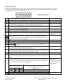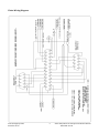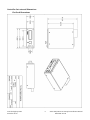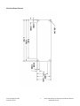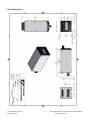
1
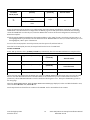
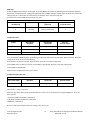
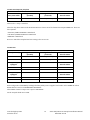
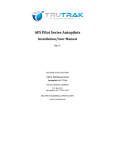
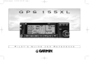
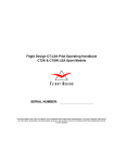
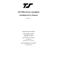
Vizion 380/385 Series Autopilots Installation Manual 8300-086 Rev IR TRUTRAK FLIGHT SYSTEMS 1500 S. Old Missouri Road Springdale, AR 72764 POSTAL SERVICE ADDRESS P.O. Box 189 Springdale, AR 72765-0189 Ph: 479-751-0250 Fax: 479-751-3397 www.trutrakap.com INSTALLATION MANUAL For Vizion 380/385 Series Autopilots TABLE OF CONTENTS Mechanical Considerations ..................................................................................................................................................................... 1 Pitot / Static Connections ........................................................................................................................................................................ 2 RFI / EMI Considerations ........................................................................................................................................................................ 2 Vizion Series Ground Checkout ............................................................................................................................................................. 3 Electrical Pin-out ......................................................................................................................................................................................... 4 Vizion Wiring Diagram ............................................................................................................................................................................. 5 Controller Dimensions/Panel Cut-outs ............................................................................................................................................. 6 GPS Setup Guide........................................................................................................................................................................................ 91 Garmin 430W and 530W ........................................................................................................................................................................................ 113 Warranty Information/Upgrade Policy .......................................................................................................................................... 17 RETURN MERCHANDISE POLICY AND PROCEDURE ........................................................................................................... 18 Revision IR Date 12/18/2013 Description Initial Release Page # Mechanical Considerations The installation information in this section is extremely important and must be clearly understood by the installer. Improper servo installation or failure to observe and diagnose installation problems prior to flight can result in extremely serious consequences, including loss of ability to control the aircraft. If there are any questions on the part of the installer it is mandatory to resolve these questions prior to flight of the aircraft. Most modern experimental aircraft use push-pull tubes to drive the primary controls. These tubes generally have a total travel of 3” or less; therefore, it is best to connect the autopilot servo to the primary control by the same method. This connection consists of an arm on the servo connected by a push-pull rod to the primary control. Rod-end bearings are required on each end of the push-pull rod. The servo arm must not rotate even near to the point called OVER CENTER, the point at which the primary aircraft control would lock up. Some aircrafts mechanical primary control installations will not allow this to occur and do not need the servo stops. This is a condition that would result from the servo being back driven when the pilot operates the controls, or from the servo itself driving the controls to a stop. To protect against this mechanical stops are supplied with the servos. These stops are drilled so that they can be mounted at different angles as required (18 intervals). In addition to the proper use of the stop it is important to know the amount of travel on the primary control that the servo can handle. With the push rod connected to the outermost hole (1 ½”) the travel on the primary cannot exceed 2 ½”, the intermediate hole 2 1/16”, and the inner hole 1 5/8”. It is important to note that at the neutral point of the control the SERVO ARM must be PERPENDICULAR to the push rod, and that the stop must be mounted so as to limit travel as near as possible to equal amounts in both directions. In certain factory-designed installations there may be well-proven exceptions. There will be installations in which space does not permit the use of the stop. When this is done the aircraft’s primary control stops must be positive and care must be taken to be sure that at the neutral point the servo arm is perpendicular to the push rod, and that the travel limits of the servo arm are not exceeded. There are installations in which the travel of the push-pull tube exceeds the allowable 2 ½”. For such installations, the drive can be applied to a bell crank at a radius point that moves the desired 2 ½” of maximum allowed travel in the outermost hole of the arm. When there is no way to have a drive point of less than 2 ½” or when the primary control is cable-driven it is necessary to use the capstan-cable servo drive. When this is done the servo should be mounted so that the 1/16” diameter cable which wraps around the capstan when extended parallel to the primary cable is approximately 3/16” from the primary cable. If the primary control travel does not exceed 5” the cable locking pin will be 180 away from the point at which the cable leaves the capstan. When the primary control is at the neutral point this means the total cable wrap around the capstan is 360 . If the primary control travel is greater than 5” the cable wrap is 720 and the pin is adjacent to the output point when the primary control is at the neutral point. The cable clamps when properly installed will not slip and thus get loose, but it is desirable to NICO press or swedge a fitting on to the cable so as to provide added assurance that the cable will not become slack. If the bridle cable is not sufficiently tight there will be lost motion in the autopilot drive. This will result in hunting (oscillation). TruTrak Flight Systems December 2013 1 Vizion 380/385 Series Autopilot Installation Manual 8300-086 Rev IR Controller Installation Mounting Considerations The Vizion controller unit is designed to mount in the aircraft instrument panel within view and reach of the pilot. Maximum recommended viewing angle should be no more than 20 deg. The maximum mounting angle the Vizion can accommodate is 10 degrees longitudinal (pitch) axis and 0 degrees lateral (roll or yaw) axis. The location should be such that the controller unit is not blocked by the glare shield on top, or by the throttles, control yoke, etc. on the bottom. Use aircraft installation standards for mounting and support of the controller. Wiring Considerations Use AWG #24 or larger wire for all connections unless otherwise specified. The standard solder pin contacts supplied in the connector kit are compatible with up to AWG #18 wire. In cases where some installations have more than one component sharing a common circuit breaker, sizing and wire gauge is based on length of wiring and current draw on units. In these cases, a larger gauge wire such as AWG #20 may be needed for power connections. Do not attach any wires to the outside of the programmer or route high current wires within six (6) inch of the programmer. Ensure that routing of the wiring is not exposed to sources of heat, RF or EMI interference. Check that there is ample space for the cabling and mating connectors. Avoid sharp bends in cabling and routing near aircraft control cables. Do not route the COM antenna coax near any autopilot components. Pitot and Static Connections All multi-servo TruTrak autopilots require connections to the pitot and static lines. The preferred method of this connection would be tee fittings near the aircraft’s altimeter. The static line for the autopilot requires due care in its construction, as excessive lag or insufficient static orifices can cause the autopilot to oscillate (hunt) in pitch. Although there is compensation within the autopilot sufficient to handle moderate amounts of lag, the importance of a good static port and line cannot be overstated. In some cases problems can be caused by having a large number of devices (including the autopilot) connected to a single, insufficient, static port. In other cases, the static line itself is adequate but there are one or more devices connected to the same line, one of which has a large static reservoir. A simple remedy for this problem if it occurs is a tee-fitting near the static port, and a dedicated line to the autopilot only. Obviously, an insufficiently-large orifice coupled with large static reservoirs can aggravate the problems associated with lag. RFI/EMI considerations The autopilot controller is shielded and does not generate any appreciable level of electromagnetic interference. Moreover, the servo lines (except for power and ground) are low-current and cannot contribute to RF interference. The servo power and ground lines do have switching currents through them, but so long as there are no parallel runs of servo power and ground lines with such things as poorly-shielded antenna lines or strobe light power lines, there is no need to shield the servo harnesses. The autopilot itself has been internally protected from RF interference and has been tested under fairly extreme conditions, such as close proximity to transmitting antennas. However, it is always good practice to insure that such antennas are properly shielded and not routed directly over or under sensitive panel-mounted electronic equipment. Most problems in this area are the result of improper RF shielding on transmitting antennas, microphone cables, and the like. The most sensitive input to the autopilot is the Control Wheel Switch input. This line should not be routed in parallel with transmitting antennas or other sources of known RF interference. If necessary, it can be shielded with the shield connection to pin 13 of the autopilot connector. TruTrak Flight Systems December 2013 2 Vizion 380/385 Series Autopilot Installation Manual 8300-086 Rev IR Vizion Ground Checkout Once installation and setup of the autopilot are complete (see Operation Manual for setup and operation instructions), a ground checkout is a good idea before the first flight of the system. This is a simple procedure to verify that the servos move in the correct direction. Follow the steps below to verify this: -1) Center both the aileron and elevator control surfaces. -2) Engage the autopilot. -3) Turn the knob clockwise, make sure the controls move to the right (stick) or clockwise (yoke). -4) Turn the knob counter-clockwise. It must be turned enough to select a left bank angle. Make sure the controls move to the left (stick) or counter-clockwise (yoke). -5) Push the knob to move the cursor to SVS and turn the knob clockwise to select a climb rate. Make sure the controls move aft. The cursor will return to the Bank selection after three seconds. -6) Push the knob to move the cursor to SVS and turn the knob counter-clockwise. It must be turned enough to select a rate of descent on the autopilot display. Make sure the controls move forward. If steps 2-6 are all verified then the Vizion is ready to be engaged in flight. *For instructions on accessing the setup menus and adjusting autopilot settings, please see section 5 of the Vizion 380/385 Operating Manual. *For recommended settings of common Experimental-Amateur Built aircraft, please see section 8 of the Vizion 380/385 Operating Manual. TruTrak Flight Systems December 2013 3 Vizion 380/385 Series Autopilot Installation Manual 8300-086 Rev IR Electrical Pin-out All TruTrak Vizion 380 and 385 autopilots have consistent wiring requirements. Therefore, this manual covers all such units, with special notations covering any differences between the units. The table below provides a brief explanation of each pin function on the main 25-pin connector P101. 1 2 3 4 5 6 7 8 9 10 11 12 13 Rear 25-Pin Connector P101 viewed from rear of unit 14 15 16 17 18 19 20 21 22 23 24 25 P101 Pin 1 2 3 4 5 6 7 8 9 10 11 12 13 14 15 16 17 18 19 20 21 22 23 P101 PIN FUNCTION View of P101 Function Facing Rear of Programmer Yaw Damper option.II PINOUT DESCRIPTION, MAIN I/O CONNECTOR DIGIFLIGHT Ground Connection. Provide #20 AWG to common grounding point. ARINC-A Digital differential signals from Garmin, Sierra, or other panel-mount receiver which provide directional steering commands (GPSS, GPSV) to ARINC-B autopilot Roll Servo Torque Control. A signal from the autopilot to the roll (aileron) servo which sets the amount of torque to be delivered by the servo. Primary Serial Input. Baud rate selectable 1200, 2400, 4800 or 9600 baud. Automatically decodes NMEA-0183, Garmin Aviation Format, or Apollo/UPSAT MovingMap or GPSS format. Provides directional reference to the autopilot. Auxiliary RS-232 Input. Presently unused. Autopilot Master (+12 to +28 V DC). The autopilot itself draws less than 0.5 ampere. Most of the current required by the autopilot system is used by the servos (up to 2A per servo). Roll (aileron) Servo control lines. These lines cause the stepping motor in the roll servo to run in the appropriate direction at the desired velocity. They are small-signal lines and do not have any substantial current-carrying capability or require any special shielding. Connect to roll servo as shown on wiring diagram. Wiring to roll servo J201 24 25 Notes 1 Ground connection for Pitch Reverse Jumper. 2 Pitch Reverse Jumper. See note 3 on External Wiring Diagram. Used for external Emergency AP Level button connection. 3 CONTROL WHEEL SWITCH 4 PITCH SERVO TORQUE Used for external Emergency AP CONTROL Level button connection. 5 PITCH SERVO TRIM SENSOR Control Wheel Switch. MASTER Connect astoshown 6 AUTOPILOT ( +12 +28 VDC )in wiring diagram to a SPST momentary switch 7 AUX RS-232 OUT (FUTURE EXPANSION) located remotely to the autopilot for convenient engage/disengage function. 8 PITCH SERVO PH2N PITCH SERVO PH2P A signal from the autopilot to the pitch servo which sets the Pitch Servo9Torque Control. 10 PITCH SERVO PH1N amount of torque to SERVO be delivered by the servo. 11 PITCH PH1P No Connection. Reserved for future expansion. Pitch Servo12 Trim Sensor. A signal from the pitch servo to the autopilot which indicates 13 GROUND ( - ) 14 condition ARINC-429 (A)and INPUT an out-of-trim its direction. 15 ARINC-429 (B) INPUT Unused. 16 ROLL SERVO TORQUE CONTROL 17 AVIATION OR NMEA-0183series SERIAL INPUT RS-232 Output.GPS Output toFORMAT G3X/AFS-5000 18 AUX RS-232 IN (FUTURE EXPANSION) 19 AUTOPILOT POWER (INTERNALLY CONNECTED TO PIN 6) ROLL SERVO PH2N Pitch Servo20 control lines. These lines cause the stepper motor in the pitch servo to run in 21 ROLL SERVO PH2P the appropriate direction at the desired velocity. They are small-signal lines and do not 22 ROLL SERVO PH1N 23 ROLL SERVO PH1P have any substantial current-carrying capability or require any special shielding. Connect 24 No Connection. Reserved for future expansion. 25 as Noshown Connection. future expansion. to pitch servo onReserved wiringfordiagram. J101 Standard Reversed TCB-A TCB-B Pin 20 J201-4 J201-5 TruTrak Flight Systems December 2013 Pin 21 J201-5 J201-4 Required for integrated control mode. Vizion 385 Only Reverse servo direction if necessary by swapping wires on pins 20 and 21. See note 2 on wiring diagram. Direction of servo arm / capstan rotation (as viewed from face of the servo body) for RIGHT aileron Servo CCW (counter-clockwise) RIGHT Servo CW (clockwise) RIGHT Unused at this time, for future expansion. 4 Vizion 380/385 Series Autopilot Installation Manual 8300-086 Rev IR Vizion Wiring Diagram TruTrak Flight Systems December 2013 5 Vizion 380/385 Series Autopilot Installation Manual 8300-086 Rev IR Controller Cut-outs and Dimensions Flat Pack Dimensions TruTrak Flight Systems December 2013 6 Vizion 380/385 Series Autopilot Installation Manual 8300-086 Rev IR Flat Pack Panel Cut-out TruTrak Flight Systems December 2013 7 Vizion 380/385 Series Autopilot Installation Manual 8300-086 Rev IR Round Dimensions TruTrak Flight Systems December 2013 8 Vizion 380/385 Series Autopilot Installation Manual 8300-086 Rev IR GPS Setup Guide Many new handheld GPS’s have adequate output required to fly a TruTrak autopilot. Although most support data output not all handhelds will provide consistent and reliable information required to fly all TruTrak autopilots. Therefore, some handhelds will not fly the airplane well. Performance may decline by putting the processor in highload situations. We require a data output rate of once per second for best performance. Some handhelds output data at longer intervals than once per second. These handhelds will cause the autopilot not to perform well in turns and it may cause overshooting and hunting. If the baud rate is selectable the optimum setting is 4800. Most handhelds will require a data cable that plugs into the handheld and provides a medium for data output. This is an accessory and is available from your GPS manufacturer. The setup procedures are in your GPS manual. If your GPS is not listed here consult your GPS manual for NMEA output setup. The autopilot must have a direct connection with the handheld GPS to provide the autopilot with RS-232. To allow the handheld GPS to be removed easily you should add a connector in your panel. We recommend that you use a 9 pin D subminature connector in your panel that will mate to the harness from the GPS. This will also allow you to wire power and ground and use the aircraft electrical system to power your handheld GPS. Garmin GPS III The Garmin III requires a Power/data cable (Garmin Part Number 010-10082-00) to provide data output. The Garmin III must be configured to provide the correct output to the autopilot. Press the MENU key twice. Select ‘Setup’. Press ENTER. Select the ‘Interface’ tab. Press ENTER. Select the NMEA format. Note: The default baud rate is 4800. This is the baud rate that will entered into the autopilot in the setup mode. Garmin GPS 92 The Garmin 92 requires a Power/data cable (Garmin Part Number 010-10082-00) to provide data output. The Garmin 92 must be configured to provide the correct output to the autopilot. Press the PAGE key until the ‘Main Menu’ appears. Select ‘Setup Menu’ and press ENTER. Next select ‘Interface.’ Press ENTER. Select NONE/NMEA. Note: The default baud rate is 4800. This is the baud rate that will entered into the autopilot in the setup mode. Garmin GPS 195 The GPS 195 provides data output every two seconds and may be slow in recognizing turns and will overshoot the desired track. This may cause the autopilot to wander and not perform well in turns. The Garmin 195 requires a Power/data cable (Garmin Part Number 010-10135-00) to provide data output. The Garmin 195 must be configured to provide the correct output to the autopilot. Press the MENU key twice. Select ‘Set-Up Menu’. Press ENTER. Select ‘Input/Output’. Press ENTER. The input/output format is ‘No In/NMEA Out.’ Note that the baud rate is automatically set at 4800 bps. Note: This is the baud rate that will need to be entered in the setup mode of the autopilot. Now the Garmin 195 is correctly set up to provide the RS-232 serial output required by your TruTrak autopilot. Garmin GPS 196 / 295 The Garmin 196 requires a Power/data cable (Garmin Part Number 010-10082-00) to provide data output. The Garmin 196 must be configured to provide the correct output to the autopilot. Press the MENU key twice. Use the arrow keypad to select the ‘SETUP’ tab. Within the Setup Menu select the ‘INTERFACE’ tab. Using the arrow keypad highlight the ‘Serial Data Format’ field. Use the arrow keypad to select ‘NMEA In/NMEA Out’ and press ENTER. Set the baud rate to 4800. Note: This is the baud rate that will need to be entered in the setup mode of the autopilot. Press MENU to enter the Advanced NMEA page. Select ‘Advanced NMEA Setup’ and press ENTER. Using the arrow keypad and the ENTER key to turn OFF ‘GPS Status (GSA, GSV)’, ‘Waypoint/Route (WPL, RTE)’, and ‘GARMIN Proprietary’. Now the Garmin 196 is correctly set up to provide the RS-232 serial output required by your TruTrak autopilot. TruTrak Flight Systems December 2013 9 Vizion 380/385 Series Autopilot Installation Manual 8300-086 Rev IR Garmin 296 The Garmin 296 must be configured to provide the correct output to the autopilot. Press the MENU key twice. Use the rocker keypad to select the SETUP in the vertical tabs. Use the rocker keypad to select the ‘COM 1’ tab. Press the down portion of the rocker keypad to select the ‘FORMAT’ field. Press ENTER and a popup window will show the available settings. Use the rocker keypad to select ‘NMEA IN / NMEA OUT’ then press ENTER. Select 4800 for the baud rate. Note: This is the baud rate that will need to be entered in the setup mode of the autopilot. Press MENU to enter the Advanced NMEA page. Select ‘Advanced NMEA Setup’ and press ENTER. Using the arrow keypad and the ENTER key to select “FAST OUTPUT” or turn OFF ‘GPS Status (GSA, GSV)’, ‘Waypoint/Route (WPL, RTE)’, and ‘GARMIN Proprietary’. Now the Garmin 296 is correctly set up to provide the RS-232 serial output required by your TruTrak autopilot. Garmin 396 / 496 The Garmin 496 must be configured to provide the correct output to the autopilot. Press the MENU key twice. Use the rocker keypad to select the SETUP in the vertical tabs. Use the rocker keypad to select the ‘Interface’ tab. Press the down portion of the rocker keypad to select the ‘Serial Data Format’ field. Press ENTER and a popup window will show the available settings. Use the rocker keypad to select ‘NMEA IN / NMEA OUT’ then press ENTER. Select 4800 for the baud rate. Note: This is the baud rate that will need to be entered in the setup mode of the autopilot. Press MENU to enter the Advanced NMEA page. Select ‘Advanced NMEA Setup’ and press ENTER. Using the arrow keypad and the ENTER key to select “FAST OUTPUT” or turn OFF ‘GPS Status (GSA, GSV)’, ‘Waypoint/Route (WPL, RTE)’, and ‘GARMIN Proprietary’. Now the Garmin 396 / 496 is correctly set up to provide the RS-232 serial output required by your TruTrak autopilot. Lowrance Airmap 100 The Lowrance Airmap 100 requires a NMEA/DGPS adapter cable to provide data output. The Lowrance Airmap 100 must be configured to provide the correct output to the autopilot. Press the MENU key then select “NMEA/DGPS CONFIG” from the “System Setup” menu. Highlight the “NMEA OUT” menu then press the right arrow key. Note: The default baud rate is 4800. This is the baud rate that will entered into the autopilot in the setup mode. Now the Lowrance Airmap 100 is correctly set up to provide the RS-232 serial output required by your TruTrak autopilot. Lowrance Airmap 1000/2000 The Lowrance Airmap 1000/2000 requires a NMEA/DGPS adapter cable to provide data output. The Lowrance Airmap 1000/2000 must be configured to provide the correct output to the autopilot. AirMap has one NMEA 0183 version 2.0 compatible communication port, Press MENU|MENU|↓ to SYSTEM SETUP|ENT. Press ↓ to COMMUNICATIONS PORT|ENT. Select 9600 Baud. This is the baud rate that will entered into the autopilot in the setup mode. Select “NMEA OUT” Now the Lowrance Airmap 1000/2000 is correctly set up to provide the RS-232 serial output required by your TruTrak autopilot. AvMap EKP IV The AvMap EKP IV requires a NMEA/DGPS adapter cable to provide data output. The AvMap EKP IV must be configured to provide the correct output to the autopilot. MENU’ 1 sec. + “COMMUNICATIONS” + ‘ENTER’ + “NMEA OUTPUT” + ‘ENTER’. The Output NMEA0183 messages are RMC, RMB that need to be selected. TruTrak Flight Systems December 2013 10 Vizion 380/385 Series Autopilot Installation Manual 8300-086 Rev IR Note: The default baud rate is 4800. This is the baud rate that will entered into the autopilot in the setup mode. The yellow wire is the Data out TX wire. Now the AvMap EKP IV is correctly set up to provide the RS-232 serial output required by your TruTrak autopilot. Garmin 155XL/250XL/300XL J1 on Garmin unit Garmin 155XL/250XL/300XL connections to TruTrak autopilot Signal Name Signal Name P101 on (Garmin) (TruTrak) TruTrak Vizion 19 GPS RS 232 OUT 2 Primary Serial Input 17 16 GPS ARINC 429 OUT A ARINC-A 14 15 GPS ARINC 429 OUT B ARINC-B 15 Press & hold MSG, rotate outer knob until I/O setup page is displayed. Press CRSR twice and rotate inner knob to select “plotting” for output to autopilot. Rotate outer knob to advance cursor to the baud rate field, select 9600. Press CRSR to finish. To set the ARINC output. Remove the data cards turn the unit on. Press “enter” in response to “Select operating mode Normal?” Press “enter” in response to “No Jeppesen database rte / prx limited to user wpts ok?” After the satellite status page is displayed for 5 seconds the unit may be turned off. With power OFF press and hold the ENT key and turn the power on (release the ENT key when the display activates). You should be in the TEST MODE. Press the CRSR key then rotate the outer knob to Select ARINC 429 CHANNEL. Press the CRSR key then rotate the inner knob to advance to OUTPUT and select “w/o GAMA labels” Garmin 430W and 530W P4001 [P5001] on Garmin 430 [530] Garmin 430 and 530 connections to TruTrak autopilot Signal Name Signal Name (Garmin) (TruTrak) P101 on TruTrak Vizion 56 GPS RS 232 OUT 1 Primary Serial Input 17 46 GPS ARINC 429 OUT A ARINC-A 14 47 GPS ARINC 429 OUT B ARINC-B 15 Power 430/530 up and turn it on while holding down the ENT key. Release the ENT key when the display activates. After the data base pages, the first page displayed is the MAIN ARINC 429 CONFIG page. While in Configuration mode, pages can be selected by ensuring the cursor is off and rotating the small right knob. To change data on the displayed Configuration Page, press the small right knob (CRSR) to turn on the cursor. Turn the large right knob to change between data fields. Turn the large or small right knob to change a field that the cursor is on. Once you have made the desired selection, press the ENT key to accept the entry. The second startup page will test the RS 232 and ARINC inputs on the ground, a good RS 232 connection will display GPS NAV and the asterisk, ARINC will display GPSS and move the stick right and left. With the MAIN ARINC 429 CONFIG page displayed, on the row labeled OUT, select SPEED Low and DATA 429 GAMA. In the VNAV row ENABLE LABELS. Advance to the MAIN RS232 CONFIG page. On the row labeled CHNL1, select OUTPUT Aviation. Note that for the Garmin units, the autopilot will need to be set for 9600 baud. UPSAT GX-50/60/65 TruTrak Flight Systems December 2013 11 Vizion 380/385 Series Autopilot Installation Manual 8300-086 Rev IR 37-Pin Connector on UPSAT GX-50/60/65 5 or 22 UPSAT GX-50/60/65 connections to TruTrak autopilot Signal Name Signal Name (UPSAT) (TruTrak) Use pin 5 – TxD1 – if GX has no GPSS P101 on TruTrak Vizion Primary Serial Input 17 Use pin 22 – TxD2 – if GX has GPSS Power the GX-50/60/65 up and turn it on while holding down the leftmost and rightmost “smart keys.” Rotate the LARGE knob to the Serial Interface Configuration “CH RX TX” page. Press SEL (the selection fields will start flashing), rotate the LARGE knob to select the port, rotate the SMALL knob to select the desired configurations, and then press ENT when complete. If both the GX unit AND the DigiFlight unit have GPSS capability, select “GPSS” for CH 2, TX column, and wire pin 17 on the DigiFlight IIVSG to pin 22 of the GX unit Otherwise select “MOVING MAP” For CH 1, TX column and wire pin 17 on the DigiFlight II / IIVS to pin 5 of the GX unit To restore the GX-50/60/65 to normal operation, switch its power off, and then back on. Note that for the GX-50/60/65 units, the autopilot will need to be set for 9600 baud. Garmin AT GNS480 Power 480 up and select the 1, 4, MENU/ ENTER keys immediately after the GNS 480 initialization is complete. After Garmin AT GNS480 connections to TruTrak autopilot P1 on GNS480 Signal Name (Garmin AT) Signal Name P101 on (TruTrak) TruTrak Vizion 22 RS232 TxD2 Primary Serial Input 17 P5 on GNS480 Signal Name (Garmin AT) Signal Name (TruTrak) P101 on TruTrak Vizion 4 429 OUT 1A ARINC-A 14 24 429 OUT 1B ARINC-B 15 restart, the first page displayed is the SETUP page. Select the SERIAL PORTS with the button next to it. Press the small knob to enter the edit mode and move to the TX column for the channel that you have connected the serial wire to (channel 2). Select MAPCOM and 9600. Press the small inner knob again to save. Then press the BACK to go back to the Setup page. Select the ARINC PORTS SETUP. With the MAIN ARINC 429 CONFIG page displayed, on the row labeled Channel 1 OUT, select and DATA ARINC 429, SPEED Low. Serial output baud rate should be set to 9600 on the GNS480. Set the TruTrak baud rate to 9600. TruTrak Flight Systems December 2013 12 Vizion 380/385 Series Autopilot Installation Manual 8300-086 Rev IR KMD 150 Power the KMD 150 up and turn it full bright. Press the MENU button then the SETUP button then the INST & DIAGS button then the DATA IN/OUT. Change the DATA OUT PUT to NEMA 0183 the manual states the Baud rate is 9600. The output pin is pin 11 and connects to the Primary Serial input on the auto pilot controller. You will need to match 9600 Baud rate in the auto pilot. KMD 150 connections to TruTrak autopilot Signal Name Signal Name (TruTrak) 37 Pin Connector on KMD 150 11 (AV NAV) P101 on TruTrak Vizion Primary Serial Input 17 Garmin GTN-650 P1001 Garmin GTN-650 connections to TruTrak autopilot Signal Name Signal Name (Garmin) (TruTrak) P101 on TruTrak Vizion 8 GPS RS 232 OUT 1 Primary Serial Input 17 10 GPS ARINC 429 OUT A ARINC-A 14 29 GPS ARINC 429 OUT B ARINC-B 15 Press and hold the HOME key when powering up the GTN-650. Release the key when the display activates. When the config mode screen shows, touch GTN Setup. Touch RS232. On channel 1 output, select Aviation. Back out to the main config menu. Touch ARINC-429. On channel 1 output, select GAMA 1, Speed LOW. Back out to the main config menu. Touch Update Config Module. Make sure the autopilot baud rate is set to 9600. Garmin 695/696/795/796 Garmin Power/Data Cable Blue Wire Garmin 696 connections to TruTrak autopilot Signal Name Signal Name (Garmin) (TruTrak) GPS RS 232 OUT 1 Primary Serial Input P101 on TruTrak Vizion 17 Select Tools -> Setup -> Interface Select the drop down menu under Serial Data Format. Choose one of the formats that outputs NMEA Out. There are three options: -Aviation In/NMEA & VHF Out is 9600 baud -GTX TIS-A In/NMEA & VHF Out is 9600 baud -NMEA Out is 4800 baud Be sure to match the autopilot baud rate setting to the correct one. TruTrak Flight Systems December 2013 13 Vizion 380/385 Series Autopilot Installation Manual 8300-086 Rev IR Garmin Aera 500/510/550/560 Garmin Power/Data Cable Blue Wire Garmin Aera connections to TruTrak autopilot Signal Name Signal Name (Garmin) (TruTrak) GPS RS 232 OUT 1 Primary Serial Input P101 on TruTrak Vizion 17 Select Tools -> Setup -> Interface Select the drop down menu under Serial Data Format. Choose one of the formats that outputs NMEA Out. There are three options: -Aviation In/NMEA & VHF Out is 9600 baud -GTX TIS-A In/NMEA & VHF Out is 9600 baud -NMEA Out is 4800 baud Be sure to match the autopilot baud rate setting to the correct one. Garmin G3X P3701 (GDU 37X) Garmin G3X connections to TruTrak autopilot Signal Name Signal Name (Garmin) (TruTrak) P101 on TruTrak Vizion 47 GPS RS 232 OUT 1 Primary Serial Input 17 48 GPS RS 232 IN 1 Serial Output 7 P731 (GSU 73) if equipped P101 on TruTrak Vizion 20 GPS ARINC 429 OUT A ARINC-A 14 21 GPS ARINC 429 OUT B ARINC-B 15 P292 (GAD 29) if equipped P101 on TruTrak Vizion 18 GPS ARINC 429 OUT A ARINC-A 14 6 GPS ARINC 429 OUT B ARINC-B 15 Enter config mode on G3X PFD by holding left softkey while power is applied. Use knob to select COMM tab. Select RS232 channel 1 and set to INTEGRATED AUTOPILOT. Select ARINC channel 1 output. Set output to AUTOPILOT. Set the autopilot baud rate to 9600. TruTrak Flight Systems December 2013 14 Vizion 380/385 Series Autopilot Installation Manual 8300-086 Rev IR Warranty On TruTrak Flight Systems Products Here at Trutrak Flight Systems, we know how important it is to feel as though the customer is purchasing a product that the manufacturer is going to stand behind. For this reason we want offer more than the basic one year warranty that is standard to this industry. The warranty on all TruTrak products will be three years from the date of purchase. Abuse and misuse of a product are not covered under this warranty. Modification to a product may void the warranty, as well as carry a penalty when upgrading to another product. This three year warranty will be for all products except the Pictorial Turn & Bank, which will continue to have a warranty of one year from the date of purchase. TruTrak Flight Systems No Penalty Upgrade Policy As the product line continues to grow, it becomes increasingly difficult to maintain a simple upgrade policy. We do want to reward our repeat customers by allowing a lower cost upgrade from one system to another; however we are not able to offer this across the board on all products. If you are considering an upgrade, please call and we will give you a quote on what this would cost. Many products that we sell today are upgradeable for only the difference in system price. Because we continually strive to have the most up to date products possible, we occasionally have to discontinue products. We will continue to offer discounted upgrades even for our discontinued products. TruTrak Flight Systems December 2013 15 Vizion 380/385 Series Autopilot Installation Manual 8300-086 Rev IR RETURN MERCHANDISE POLICY AND PROCEDURE Under no circumstances should products be returned to TruTrak without first obtaining a Return of Merchandise Authorization number (RMA #) from TruTrak. An RMA# may be obtained by contacting us at 866-878-8725. Products that do not have an RMA # will not be processed. Please include documentation stating the reason for the return and describing any symptoms, failure modes, suspected causes of damage, diagnostics performed, data collected, etc. Product(s) should be packaged in their original shipping containers. In lieu of this, they should be very carefully packaged in containers suitable to protect them during transit. For your protection, items should be insured for the full value. Note that damage caused during shipping will not be repaired under warranty. The outside of the box must be clearly marked with the RMA # issued by TruTrak and the RMA # must also be noted on the return documents. Products will be returned to the customer at no charge via FedEx Ground or UPS Ground. If customer requests expedited shipping (2nd Day or Overnight) they will be charged the shipping cost and must supply a credit card number. INTERNATIONAL SHIPMENTS: Trutrak sends all International shipments with an insurance value on all products. Trutrak pays for shipping only. The customer is responsible for any and all additional fees, duties, taxes associated with the shipment. When sending products to Trutrak for repair or otherwise please be advised that the customer is responsible for all charges and fees associated with shipment. For your protection, items should be insured for the full value. Trutrak states on all product returns “WARRANTY REPAIR AT NO CHARGE TO CUSTOMER. A COMMERCIAL INVOICE VALUE OF $___ GIVEN FOR INSURANCE PURPOSES ONLY” Please keep in mind that your government or another entity in your country may impose a charge for custom and/or brokerage fees, duties and taxes on items received from the US. These charges do not originate from our company nor do we benefit from them in any way. You are responsible for payment of all custom and brokerage fees, duties and taxes that may be imposed when these goods are imported into your country. Send ALL return shipments to: Trutrak Flight Systems, Inc., 1500 South Old Missouri Road, Springdale, AR 72764 USA Attention: Returns Dept. RMA# ______________ TruTrak Flight Systems December 2013 16 Vizion 380/385 Series Autopilot Installation Manual 8300-086 Rev IR For Installation Support: +1 479 751 0250 option 2 for support Monday through Friday, 8am-5pm Central time Email [email protected] Check our customer forum at www.trutrakap.com/forum Follow us on Facebook, Trutrak Flight Systems, Inc. TRUTRAK FLIGHT SYSTEMS 1500 S. Old Missouri Road Springdale, AR 72764 POSTAL SERVICE ADDRESS P.O. Box 189 Springdale, AR 72765-0189 Ph: 479-751-0250 Fax: 479-751-3397 Toll free: 866-TRUTRAK 866-(878-8725) www.trutrakap.com