1
Via Disraeli, 8 42124 REGGIO EMILIA - ITALY
Tel. +39 0522 369711 Fax +39 0522 791052
E-mail: [email protected]
P.IVA – C.F. 01979170352
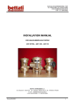
INSTALLATION MANUAL
FOR INERT GAS SYSTEM
IG 100 – IG 01 – IG 55 – IG 541
BETTATI ANTINCENDIO s.r.l.
Via Disraeli, 8 - 42124 RE Tel. +39 0522 / 369711 (R.A.) - fax +39 0522 / 791052
E-mail: [email protected]
P.IVA 01979170352 C.F. 01979170352
Revised 07/2013
Via Disraeli, 8 42124 REGGIO EMILIA - ITALY
Tel. +39 0522 369711 Fax +39 0522 791052
E-mail: [email protected]
P.IVA – C.F. 01979170352
Revised 07/2013
2
Via Disraeli, 8 42124 REGGIO EMILIA - ITALY
Tel. +39 0522 369711 Fax +39 0522 791052
E-mail: [email protected]
P.IVA – C.F. 01979170352
Contents
1.
Introduction......................................................................................................................................................... 5
1.1 General information ............................................................................................................................................... 5
1.2 Scope and purpose of manual................................................................................................................................ 7
1.3 Standards and Code of practice ............................................................................................................................. 7
1.4 Transport and material management .................................................................................................................... 8
1.5 Preliminary control and operations: .................................................................................................................... 10
2
System description .............................................................................................................................................12
2.1 Single cylinder system .......................................................................................................................................... 12
2.2 Multi-cylinder system (number of cylinders less than 20) ................................................................................... 12
2.3 Multi-cylinder system (number of cylinders more than 20) with 2 solenoid actuators....................................... 14
2.4 Multi-cylinder system with directional valves...................................................................................................... 15
2.5 Components description ...................................................................................................................................... 16
2.5.1 Cylinder ............................................................................................................................................................. 16
2.5.2 Discharge valve ................................................................................................................................................. 18
2.5.3 Solenoid/manual actuator ............................................................................................................................... 21
2.5.4 Pressure gauge with supervisory pressure switch ........................................................................................... 22
2.5.5 Pilot flex hose ................................................................................................................................................... 23
2.5.6 Flex discharge hose........................................................................................................................................... 23
2.5.7 Manifold ........................................................................................................................................................... 25
2.5.8 Pressure reducing device .................................................................................................................................. 29
2.5.9 Check valve ....................................................................................................................................................... 30
2.5.10 Non-return valve ............................................................................................................................................. 31
2.5.11 Pipeline pressure switch ................................................................................................................................. 32
2.5.12 Overpressure damper ..................................................................................................................................... 34
2.5.13 Nozzle............................................................................................................................................................ 36
2.5.14 Directional valves ........................................................................................................................................ 37
2.5.15 Cylinder fixing components......................................................................................................................... 40
2.5.16 Manifold fixing components ....................................................................................................................... 43
3
Mechanical and electrical installation .................................................................................................................45
3.1 Procedure of installation ...................................................................................................................................... 45
3.2 Discharge manifold installation............................................................................................................................ 47
3.2.1 Discharge manifold fixing ................................................................................................................................. 49
3.3 Cylinder fixing ....................................................................................................................................................... 51
3.3.1 General consideration for cylinder installation ................................................................................................ 51
3.3.2 Single cylinder fixing ......................................................................................................................................... 54
3.3.3 Single-row multi-cylinder fixing ........................................................................................................................ 55
3.3.4 Double-row multi-cylinder fixing ...................................................................................................................... 57
3.4 Discharge flex hose installation............................................................................................................................ 62
3.5 Pressure gauge with supervisory pressure switch installation ............................................................................ 63
3.6 Solenoid / manual actuator installation ............................................................................................................... 64
3.7 Pneumatic connections ........................................................................................................................................ 65
3.7.1 Single cylinder ................................................................................................................................................... 65
3.7.2 Multi-cylinder system - pilot cylinder ............................................................................................................... 66
Revised 07/2013
3
Via Disraeli, 8 42124 REGGIO EMILIA - ITALY
Tel. +39 0522 369711 Fax +39 0522 791052
E-mail: [email protected]
P.IVA – C.F. 01979170352
3.7.3 Multi-cylinder system - slave cylinders............................................................................................................. 66
3.8 Pipeline and nozzle installation ............................................................................................................................ 67
3.9 Installation of overpressure dampers .................................................................................................................... 68
3.9.1 Conventional kit installation ............................................................................................................................. 69
3.9.2 “L” External grill kit / Dynamic weather louver installation ............................................................................. 71
3.9.3 “Z” frame installation ....................................................................................................................................... 72
4
Installation of directional valves (if applicable)...................................................................................................75
4.1 Procedure of installation ...................................................................................................................................... 75
4.2 Discharge manifold installation............................................................................................................................ 76
4.3 Installation of the directional valve assemblies ................................................................................................... 77
4.4 Installation of pneumatic connections ................................................................................................................. 79
4.4.1 Connections on the pneumatic cylinder ........................................................................................................... 80
4.4.2 Connections on the cylinder rack ..................................................................................................................... 81
4.4.3 Connection of the pilot valves to the actuating piston inlets ........................................................................... 82
4.4.4 Connection of slave cylinders ........................................................................................................................... 83
4.4.5 Connection of pneumatic piston outlets to discharge valves ........................................................................... 84
5.
Mechanical system acceptance ...........................................................................................................................86
5.1 Testing procedures ............................................................................................................................................... 86
5.1.1 Protected area volume ..................................................................................................................................... 87
5.1.2 Protected area integrity.................................................................................................................................... 87
5.1.3 Design correspondence .................................................................................................................................... 89
5.1.4 Pipeline fixing ................................................................................................................................................... 89
5.1.5 Pipeline locking ................................................................................................................................................. 89
5.1.6 Pneumatic circuit .............................................................................................................................................. 90
5.1.7 Functional test .................................................................................................................................................. 92
6.
Testing for directional valve systems (if applicable) ............................................................................................95
6.1 Check the correct functioning of the system ....................................................................................................... 95
7
Extinguishing system start-up .............................................................................................................................98
7.1 Electrical-mechanical connection of the solenoid / manual actuator ................................................................. 98
Revised 07/2013
4
Via Disraeli, 8 42124 REGGIO EMILIA - ITALY
Tel. +39 0522 369711 Fax +39 0522 791052
E-mail: [email protected]
P.IVA – C.F. 01979170352
1.
Introduction
1.1
General information
The systems described in this manual use inert gases as extinguishing agents, and consist of two basic units.
The basic units used for these system are:
Storage/Distribution units (fig. 1.1);
Detection and alarm devices and control panels (fig. 1.2).
Storage/Distribution units
Tab. 1.1 List of components
1
2
3
4
5
Standard Ref.
List of components
EN 12094-8
EN 12094-5
PED 97/36/CE
EN 12094-4
TPED 99/36/CE
Connectors
Directional valve
Discharge Manifold
Discharge Valve and its actuator
Cylinder
Pressure gauge and pressure
switch
Non-return Valve and Check Valve
Nozzle
EN 12094:10
6
7 EN 12094-13
8 EN 12094-7
8
7
3
4
1
6
5
2
Fig. 1.1 List of mechanical components
Revised 07/2013
5
Via Disraeli, 8 42124 REGGIO EMILIA - ITALY
Tel. +39 0522 369711 Fax +39 0522 791052
E-mail: [email protected]
P.IVA – C.F. 01979170352
Detection and alarm devices and control panel
Smoke and
Heat
Detectors
EN 54-7-5
Manual release point
EN 12094-3 EN 54-11
Manual
Emergency stop
EN 12094-3 En 54-11
Manual call point
EN 54-11
Pressure Gauge with
supervisory
Pressure Switch
EN 12094-10
Conventional
fire-fighting
extinguishing
Panel
EN 12094-1
Pre-Alarm
Alarm
Fault
Pressure Gauge and Alarm
Remoting
Solenoid actuator
EN 12094-4
Acoustic siren
EN 54-3
Audio-Visual Panel
EN 54-3
Fig.1.2 List of components of the detection system
Revised 07/2013
6
Via Disraeli, 8 42124 REGGIO EMILIA - ITALY
Tel. +39 0522 369711 Fax +39 0522 791052
E-mail: [email protected]
P.IVA – C.F. 01979170352
1.2
Scope and purpose of manual
This manual is a comprehensive guide containing all recommendations necessary to install the ““Argon IG01”,
“Nitrogen IG100”, “Nitrogen+Argon IG55” and “Nitrogen+Argon+CO2 IG541” Gas Extinguishing Systems, and
it concerns the 300 bar gas extinguishing systems supplied by Bettati Antincendio srl.
Discharge of an unsecured and disconnected cylinder could be extremely dangerous and may
result in injury or death, and/or damage the property.
NEVER complete all pneumatic connections between cylinders and the actuating system as
well as the electrical connection between the solenoid actuator and the control unit UNTIL
cylinders are properly secured in the cylinder rack and the discharge connection fittings are
connected to the pipeline.
High-pressure-stored gases are involved in the installation of this system
The installation of the system must comply with the requirement of this manual
The installation shall be done ONLY by recommended Bettati Antincendio trained technicians
1.3
Standards and Code of practice
Systems that use extinguishing agents “Argon IG01”, “Nitrogen IG100”, “Nitrogen+Argon IG55” and
“Nitrogen+Argon+CO2 IG541” are designed according to these standards:
UNI EN 15004-1:2008 “Fixed firefighting systems. Gas extinguishing systems. Part 1: Design,
installation and maintenance”.
UNI EN 15004-7:2008 “Fixed firefighting systems. Gas extinguishing systems. Part 7: Physical
properties and system design of gas extinguishing systems for IG-01 extinguishant”.
UNI EN 15004-8:2008 “Fixed firefighting systems. Gas extinguishing systems. Part 8: Physical
properties and system design of gas extinguishing systems for IG-100 extinguishant”.
UNI EN 15004-9:2008 “Fixed firefighting systems. Gas extinguishing systems. Physical properties and
system design of gas extinguishing systems for IG-55 extinguishant”.
UNI EN 15004-10:2008 “Fixed firefighting systems. Gas extinguishing systems. Physical properties
and system design of gas extinguishing systems for IG-541 extinguishant”
Components used in the system that use extinguishing agent “Argon IG01”, “Nitrogen IG100”,
“Nitrogen+Argon IG55” and “Nitrogen+Argon+CO2 IG541” are designed according to these standards:
UNI EN 12094-4:2004 “Fixed firefighting systems. Components for gas extinguishing systems.
Requirements and test methods for container valve assemblies and their actuators”.
UNI EN 12094-5:2004 “Fixed firefighting systems. Components for gas extinguishing systems.
Requirements and test methods for high and low pressure selector valves and their actuators”.
UNI EN 12094-6:2006 “Fixed firefighting systems. Components for gas extinguishing systems.
Requirements and test methods for non-electrical disable devices”.
UNI EN 12094-8:2006 “Fixed firefighting systems. Components for gas extinguishing systems.
Requirements and test methods for flexible connectors”.
UNI EN 12094-10:2004 “Fixed firefighting systems - Components for gas extinguishing systems .
Requirements and test methods for pressure gauges and pressure switches”
UNI EN 12094-13:2002 “Fixed firefighting systems. Components for gas extinguishing systems.
Requirements and test methods for check valves and non-return valves”.
Revised 07/2013
7
Via Disraeli, 8 42124 REGGIO EMILIA - ITALY
Tel. +39 0522 369711 Fax +39 0522 791052
E-mail: [email protected]
P.IVA – C.F. 01979170352
1.4
Transport and material management
For gas extinguishing cylinders transport, proper means must be used and the MSDS (Material Safety Data
Sheet), attached with the technical file, must be consulted.
The cylinder must:
• remain either in the pallets or in the proper containers until the ground
placement (fig.1.3),
Fig. 1.3b Cylinders placed in a
container (vertical position)
Fig. 1.3a Cylinders located on pallets
(horizontal position)
•
be moved by skilled personnel and with proper means,
During the cylinders handling the valve cap must be correctly placed on the top of the cylinder
(Fig. 1.4)
NO
CORRECT
Fig.1.4 Trailer truck used to move cylinders
•
•
•
•
be placed in a clean and dry place,
be stored in a sheltered place, protected from heat and atmospheric agents,
avoid aisles and other high traffic areas where physical damage or tampering is more likely. Containers
should never be mounted where the container could potentially be splashed with, or submerged in
any liquid,
cylinder valve cap and all the safety plugs for the pressure connection (fig. 1.5) must be in place when
the cylinders are moved or transported (fig. 1.4),
Revised 07/2013
8
Via Disraeli, 8 42124 REGGIO EMILIA - ITALY
Tel. +39 0522 369711 Fax +39 0522 791052
E-mail: [email protected]
P.IVA – C.F. 01979170352
Fig.1.5 Cylinder’s cap and Anti-recoil details
•
Ensure the correct installation position of every cylinder, as shown in the technical drawing.
Every cylinder is provided with specific nameplates (fig. 1.6) that:
• provides the specific information (contained gas, serial number, operating pressure, weight
information: tare, gross and agent);
• shows the valve outlet position (this nameplate is useful for the placement of the cylinder, as the valve
outlet is hidden by cylinder cap);
• describes the safety information for handling and storage;
• describes the transport data.
Cylinder nameplate
Safety nameplate
Transport tag
Valve outlet nameplate
Fig.1.6 Cylinder tags and labels
Revised 07/2013
9
Via Disraeli, 8 42124 REGGIO EMILIA - ITALY
Tel. +39 0522 369711 Fax +39 0522 791052
E-mail: [email protected]
P.IVA – C.F. 01979170352
1.5
Preliminary control and operations:
• Check that the cylinders support base (especially in case of floor or underfloor voids
placement) and the entire structure can support the total loads shown in the following
tab. 1.2;
Tab. 1.2 Cylinder and extinguishing agent characteristics
300 bar Cylinders
Cylinder
capacity
[L]
140
Ext.diam.
[mm]
360
NITROGEN
Cylinder
capacity
[L]
140
Length [mm]
Weight
[kg]
1750±30
Agent weight [kg]
Valv. weight [kg]
Tot. weight [kg]
190±3
43.5
2.5
236±3
Length [mm]
Weight
[kg]
1750±30
Agent weight [kg]
Valv. weight [kg]
Tot. weight [kg]
190±3
70.5
2.5
263±3
Ext.diam.
[mm]
360
ARGON
Cylinder
capacity [L]
140
Ext.diam.
[mm]
360
IG55
Cylinder
capacity [L]
140
Ext.diam.
[mm]
360
IG541
•
•
Length [mm]
1750±30
Agent weight [kg]
Valv. weight [kg]
Tot. weight [kg]
Length [mm]
1750±30
Agent weight [kg]
Valv. weight [kg]
Tot. weight [kg]
Weight
[kg]
190±3
56.1
2.5
248.6±3
Weight
[kg]
190±3
57.9
2.5
250.4±3
Cylinder
capacity
[L]
80
Ext.diam.
[mm]
273
NITROGEN
Cylinder
capacity
[L]
80
Ext.diam.
[mm]
273
ARGON
Cylinder
capacity [L]
80
Ext.diam.
[mm]
273
IG55
Cylinder
capacity [L]
80
IG541
Ext.diam.
[mm]
273
Length [mm]
Weight
[kg]
1790±30
Agent weight [kg]
Valv. weight [kg]
Tot. weight [kg]
114±3
24.9
2.5
141.4±3
Length [mm]
Weight
[kg]
1790±30
Agent weight [kg]
Valv. weight [kg]
Tot. weight [kg]
114±3
40.3
2.5
156.8±3
Length [mm]
1790±30
Agent weight [kg]
Valv. weight [kg]
Tot. weight [kg]
Length [mm]
1790±30
Agent weight [kg]
Valv. weight [kg]
Tot. weight [kg]
Weight
[kg]
114±3
32.1
2.5
148.6±3
Weight
[kg]
114±3
33.1
2.5
149.6±3
Check that the protected area has kept the design volume and that the structural solidity
of the walls for the right installation of the pipes and cylinders can be guaranteed ;
Make a visual check of the material, ensuring that the quantity of the items matches the
quantity reported on the data sheet and that it has got the technical specifications
reported on the manual “Engineered System”;
All the other materials must be stored in a shelter place, protected from the atmospheric agents, in order to
prevent any damage.
The cylinder valve cap can be removed ONLY after the installation of the cylinders.
In order to avoid accidental discharge, the connection between hose and ¼” nipple placed on
the solenoid actuator must be done ONLY after a suitable test. (see Chapter 5)
Revised 07/2013
10
Via Disraeli, 8 42124 REGGIO EMILIA - ITALY
Tel. +39 0522 369711 Fax +39 0522 791052
E-mail: [email protected]
P.IVA – C.F. 01979170352
The cylinders and the accompanying hardware will be supplied with the necessary accessory, in accordance
with Bettati Antincendio standards.
The cylinder installation shall be wall-mounted, therefore a suitable place must be found. The brackets and
the raw plugs used for the installation must support the total load. Normally, the cylinder should be placed in
a dry and well-ventilated place, in order to avoid corrosion and usury phenomena.
Execute the following control procedure; in case of not accordance with the original design, please inform
Bettati Antincendio before the installation begins.
Revised 07/2013
11
Via Disraeli, 8 42124 REGGIO EMILIA - ITALY
Tel. +39 0522 369711 Fax +39 0522 791052
E-mail: [email protected]
P.IVA – C.F. 01979170352
2
System description
The gaseous extinguishing systems “Argon IG01”, “Nitrogen IG100”, “Nitrogen +Argon IG55” and “Nitrogen
+Argon+CO2 IG541” can be subdivided in four different typologies:
Single cylinder systems
Multi-cylinder systems, number of cylinders less than 20
Multi-cylinder systems, number of cylinders more than 20
Multi-cylinder systems with directional valves
2.1
Single cylinder system
1
2
3
4
5
6
N°
80 L or 140 L pressurized cylinders with extinguishing gas at
300 bar
Inert gas valve with 3/4” outlet and anti-recoil cap
Bettati solenoid/manual actuator composed by: solenoid
pilot valve 24 Vcc, manual swivel actuator, pressure gauge
with supervisory pressure switch 0-400 bar, bleeder valve
3/16” pilot flex hose
3/4"discharge flex hose
Pressure reducing device
COMPONENT
Fig. 2.1 Single cylinder
Revised 07/2013
12
Via Disraeli, 8 42124 REGGIO EMILIA - ITALY
Tel. +39 0522 369711 Fax +39 0522 791052
E-mail: [email protected]
P.IVA – C.F. 01979170352
2.2
Multi-cylinder system (number of cylinders less than 20)
1
2
3
4
5
6
7
8
9
10
11
N°
80 L or 140 L pressurized cylinders with extinguishing gas at
300 bar
Inert gas valve with 3/4” outlet and anti-recoil cap
Bettati solenoid/manual actuator composed by: solenoid pilot
valve 24 Vcc, manual swivel actuator, pressure gauge with
supervisory pressure switch 0-400 bar, bleeder valve
pressure gauge assembly with supervisory pressure switch
0-400 bar (N.O.)
3/16” pilot flex hose
3/4"discharge flex hose
3/4”check valve
3/4” plug
Discharge manifold made of steel XXS type
Pressure reducing device
Manifold plug
COMPONENT
Fig. 2.2 Multiple Cylinders
Revised 07/2013
13
Via Disraeli, 8 42124 REGGIO EMILIA - ITALY
Tel. +39 0522 369711 Fax +39 0522 791052
E-mail: [email protected]
P.IVA – C.F. 01979170352
2.3
Multi-cylinder system (number of cylinders more than 20) with 2 solenoid actuators
Cylinder 1
1
2
3
4
5
6
7
8
9
10
11
N°
Cylinder 2
Cylinder 21
80 L or 140 L pressurized cylinders with extinguishing gas at
300 bar
Inert gas valve with 3/4” outlet and anti-recoil cap
Bettati solenoid/manual actuator composed by: solenoid pilot
valve 24 Vcc, manual swivel actuator, pressure gauge with
supervisory pressure switch (N.O.), bleeder valve
pressure gauge assembly with supervisory pressure switch
(N.O.)
3/16”pilot flex hose
3/4"discharge flex hose
3/4”check valve
3/4” plug
Discharge manifold made of steel XXS type
Pressure reducing device
Manifold plug
COMPONENT
Fig. 2.3 Multiple Cylinders, more than 20 cylinders system
Revised 07/2013
14
Via Disraeli, 8 42124 REGGIO EMILIA - ITALY
Tel. +39 0522 369711 Fax +39 0522 791052
E-mail: [email protected]
P.IVA – C.F. 01979170352
2.4
Multi-cylinder system with directional valves
1
2
3
4
5
N°
Pilot cylinder assembly
Slave cylinder assembly
Manifold
Directional valve assembly
3/16” pilot flex hose
COMPONENT
Fig. 2.4 Multi-cylinder system with 2 directional valves
Fig. 2.5 Inert gas extinguishing system with directional valves
Revised 07/2013
15
Via Disraeli, 8 42124 REGGIO EMILIA - ITALY
Tel. +39 0522 369711 Fax +39 0522 791052
E-mail: [email protected]
P.IVA – C.F. 01979170352
2.5
Components description
The following sections describe the components of Bettati Antincendio srl systems. For more details, please
contact Bettati Antincendio at this address:
BETTATI ANTINCENDIO srl
Via B. Disraeli, 8
42124 Reggio Emilia
Tel. +39 0522/369711Fax. +39 0522/791052
e-mail [email protected]
2.5.1
Cylinder
The seamless steel cylinders are manufactured according to EN 1964-1 : 2010/35/UE (TPED)
Capacity
(L)
80
140
External
diameter
(mm)
269
355.6
Inert gas
Argon IG-01
Nitrogen IG-100
IG-55
IG-541
Length
Weight
Connection
(mm)
1790
1810
(kg)
103
215
(inch)
1” NPT G
1” NPT G
Color of body
red – RAL3000
red – RAL3000
red – RAL3000
red – RAL3000
Test
pressure
(bar)
450
450
Working
Pressure
(bar)
300
300
Color of shoulder
green – RAL6018
green – RAL6018
green – RAL6018
green – RAL6018
Fig. 2.6 Cylinder characteristics
Technical specifications about the cylinder (such as capacity, weight, wall thickness, etc.) are stamped on the
cylinder shoulder, as shown in figure:
Revised 07/2013
16
Via Disraeli, 8 42124 REGGIO EMILIA - ITALY
Tel. +39 0522 369711 Fax +39 0522 791052
E-mail: [email protected]
P.IVA – C.F. 01979170352
POS
DESCRIPTION
POS
DESCRIPTION
1
Number of cylinder
8
Manufacturing Country
2
Cylinder thread
9
Stamp of the notified body
3
Weight of the empty cylinder
10
Non destructive inspection (ultrasonic)
4
Minimum wall thickness
11
Minimum water capacity
5
TPED mark
12
Nominal pressure (PN) and test pressure (PH)
6
Temperature test
13
Test date
7
Standard
Fig. 2.7 Technical specifications about the cylinder are stamped on the shoulder
Revised 07/2013
17
Via Disraeli, 8 42124 REGGIO EMILIA - ITALY
Tel. +39 0522 369711 Fax +39 0522 791052
E-mail: [email protected]
P.IVA – C.F. 01979170352
2.5.2
Discharge valve
The discharge valve is a pressure operated cylinder valve having brass body, activated through an operating
piston at the top. The discharge valve is certified according to the requirements of EN 12094-4.
1
2
3
4
5
6
7
8
9
N°
Brass body
Device for refill on site
Plug
Anti-recoil cap
Pressure socket anti-recoil cap
Bursting safety disc
Safety disc plug
Pressure socket
Detail of CE marking
COMPONENT
Fig. 2.8 300 bar discharge valve with CE marking
Revised 07/2013
18
Via Disraeli, 8 42124 REGGIO EMILIA - ITALY
Tel. +39 0522 369711 Fax +39 0522 791052
E-mail: [email protected]
P.IVA – C.F. 01979170352
Fig. 2.9 Discharge valve, inlet 1” NPT – outlet 3/4" BSPP
Pilot valve assembly
1
2
3
4
5
6
7/A
7/B
8
N°
Valve body
Pressure gauge with supervisory pressure switch
Pressure outlet with 1/8” BSPT x 1/4" BSPP nipple
Manual handwheel
Solenoid 24 Vcc 11 W
3/16”pilot flex hose
TEE 1/4" BSPP - 1/4" NPT - 1/4" BSPP
Elbow 1/4" NPT - 1/4" BSPP
Safety pin
COMPONENT
Fig. 2.10 Pilot valve assembly
Revised 07/2013
19
Via Disraeli, 8 42124 REGGIO EMILIA - ITALY
Tel. +39 0522 369711 Fax +39 0522 791052
E-mail: [email protected]
P.IVA – C.F. 01979170352
Slave valve assembly
2 pi
1
2
3
4/A
4/B
N°
Valve body
Pressure gauge with supervisory pressure switch
3/16”pilot flex hose
TEE 1/4" BSPP - 1/4" NPT - 1/4" BSPP
Elbow 1/4" NPT - 1/4" BSPP
COMPONENT
Fig. 2.11 Slave valve assembly
Actuated mode / stand-by mode
Actuated Mode
Stand-by mode
Fig. 2.12 Actuated mode and stand-by mode of the discharge valve
Revised 07/2013
20
Via Disraeli, 8 42124 REGGIO EMILIA - ITALY
Tel. +39 0522 369711 Fax +39 0522 791052
E-mail: [email protected]
P.IVA – C.F. 01979170352
2.5.3 Solenoid/manual actuator
This solenoid / manual actuator is used to open the pilot discharge valve; its assembly includes a pressure
gauge with supervisory pressure switch, a bleeder valve and a swivel connection.
The solenoid/manual actuator is certified in
compliance with EN 12094-4 and the
pressure gauge with EN 12094-10
The solenoid/manual actuator can be
manually removed from the valve through
the swivel nut (7) with the cylinder
pressurized.
1 Body
Pressure gauge with supervisory pressure switch 0-400 bar,
2
∅40
3 Solenoid 24 Vcc 11 W
4 Bleeder valve
5 Safety pin
6 Manual swivel actuator
7 Swivel nut (connection to valve)
N° COMPONENT
Fig. 2.13 Solenoid manual actuator assembly
Revised 07/2013
21
Via Disraeli, 8 42124 REGGIO EMILIA - ITALY
Tel. +39 0522 369711 Fax +39 0522 791052
E-mail: [email protected]
P.IVA – C.F. 01979170352
2.5.4 Pressure gauge with supervisory pressure switch
The unit is required for the installation on the slave cylinder, in order to provide a continuous monitoring of
the internal pressure of the container.
The gauge is
according to
UNI EN 12094-10
certified
The pressure gauge assembly
can be manually removed
from the valve through the
swivel nut (3) with the
cylinder pressurized.
1 Pressure socket body
Pressure gauge with supervisory pressure switch
2
0-400 bar ∅40
3 Swivel nut (connection to valve)
4 Electrical plug
N°
COMPONENT
Fig. 2.14 Pressure gauge
N.B. As shown in fig. 2.12, the pressure gauge presents a calibrated pressure (shown in red) which is
determined calculating the working pressure at -20°C and reduced by 10%.
W.P@-20°C ≈240 bar
240 bar – 10% ≈ 220 bar
To know which electrical resistance shall be used for all the electrical connections, see the
technical manual of the extinguishing panel (which is not included in this documentation).
Revised 07/2013
22
Via Disraeli, 8 42124 REGGIO EMILIA - ITALY
Tel. +39 0522 369711 Fax +39 0522 791052
E-mail: [email protected]
P.IVA – C.F. 01979170352
2.5.5
Pilot flex hose
This flexible connectors are used to interconnect cylinder valves and all the mechanical devices involved in
the actuating system. 3/16" reinforced rubber flex hose has threaded connections that allow interface
between components. The flexible hoses are certified according to UNI EN 12094-8.
Hose
Nominal
Diameter
(inch)
3/16”
1
2
3
4
5
6
7
N°
Connections
1/4" BSPP
Working
Pressure
(bar)
360
Nipple 1/8 BSPT – ¼ BSPP
Swivel nut 1/4" BSPP
Actuator – pilot cylinder 3/16” hose connection
TEE 1/4" BSPP - 1/4" NPT - 1/4" BSPP
Cylinder – cylinder 3/16” hose connection
Elbow 1/4" NPT - 1/4" BSPP
CE marking
COMPONENT
Fig. 2.15 Flex hose connectors
Revised 07/2013
23
Via Disraeli, 8 42124 REGGIO EMILIA - ITALY
Tel. +39 0522 369711 Fax +39 0522 791052
E-mail: [email protected]
P.IVA – C.F. 01979170352
2.5.6
Flex discharge hose
This flexible hose is connected to the valve outlet and allows the discharge of the extinguishing gas.
The flexible hoses are certified complying with UNI EN 12094-8.
Hose
Nominal
Diameter
(inch)
3/4”
Connections
Working
Pressure
(bar)
3/4" BSPP
360
1 3/4" discharge hose
2 3/4" BSPP swivel nut
3 CE marking
N°
COMPONENT
Fig. 2.16 Flex discharge hose
Revised 07/2013
24
Via Disraeli, 8 42124 REGGIO EMILIA - ITALY
Tel. +39 0522 369711 Fax +39 0522 791052
E-mail: [email protected]
P.IVA – C.F. 01979170352
2.5.7
Manifold
The manifold is used to convey the extinguishing gas contained in cylinders to the pipeline. Every manifolds,
completed with plugs, check valves and restrictor, is tested by hydrostatic test complying with PED 97/23/EC.
Cylinder capacity
(L)
80
80
Cylinder
configuration
Single row
Double row
Directional valve
Cylinder capacity
(L)
80
80
Cylinder
configuration
Single row
Double row
Directional valve
NO
NO
NO
NO
1
2
3
4
5
6
8
N°
Nr. max.
cylinders
6
12
A
(mm)
125
75
B
(mm)
0
100
C
(mm)
300
200
D
(mm)
300
300
E
(mm)
125
75
L
(mm)
1750
1750
Nr. max.
cylinders
12
24
A
(mm)
125
75
B
(mm)
0
100
C
(mm)
300
200
D
(mm)
300
300
E
(mm)
125
75
L
(mm)
3500
3500
2” NPT manifold plug ASA 6000
3/4" check valve
XXS type pipe
2” NPT straight coupling
3/4" plug
2” NPT pressure reducing device
CE marking
COMPONENT
Fig. 2.17 Manifolds for 80L cylinder rack, without directional valves
Revised 07/2013
25
Via Disraeli, 8 42124 REGGIO EMILIA - ITALY
Tel. +39 0522 369711 Fax +39 0522 791052
E-mail: [email protected]
P.IVA – C.F. 01979170352
Cylinder capacity
(L)
80
80
Cylinder
configuration
Single row
Double row
Directional valve
Cylinder capacity
(L)
80
80
Cylinder
configuration
Single row
Double row
Directional valve
YES
YES
YES
YES
1
2
3
4
5
7
8
N°
Nr. max.
cylinders
6
12
A
(mm)
125
75
B
(mm)
0
100
C
(mm)
300
200
D
(mm)
300
300
E
(mm)
300
300
L
(mm)
1925
1975
Nr. max.
cylinders
12
24
A
(mm)
125
75
B
(mm)
0
100
C
(mm)
300
200
D
(mm)
300
300
E
(mm)
300
300
L
(mm)
3850
3950
2” NPT manifold plug ASA 6000
3/4" check valve
XXS type pipe
2” NPT straight coupling
3/4" plug
ASA 6000 90° elbow
CE marking
COMPONENT
Fig. 2.18 Manifolds for 80L cylinder rack, with directional valves
Revised 07/2013
26
Via Disraeli, 8 42124 REGGIO EMILIA - ITALY
Tel. +39 0522 369711 Fax +39 0522 791052
E-mail: [email protected]
P.IVA – C.F. 01979170352
Cylinder capacity
(L)
140
140
Cylinder
configuration
Single row
Double row
Directional valve
Cylinder capacity
(L)
140
140
Cylinder
configuration
Single row
Double row
Directional valve
NO
NO
NO
NO
1
2
3
4
5
6
8
N°
Nr. max.
cylinders
5
10
A
(mm)
175
125
B
(mm)
0
100
C
(mm)
400
300
D
(mm)
400
400
E
(mm)
175
125
L
(mm)
1950
1950
Nr. max.
cylinders
10
20
A
(mm)
175
125
B
(mm)
0
100
C
(mm)
400
300
D
(mm)
400
400
E
(mm)
175
125
L
(mm)
3900
3900
2” NPT manifold plug ASA 6000
3/4" check valve
XXS type pipe
2” NPT straight coupling
3/4" plug
2” NPT pressure reducing device
CE marking
COMPONENT
Fig. 2.19 Manifolds for 140L cylinder rack, without directional valves
Revised 07/2013
27
Via Disraeli, 8 42124 REGGIO EMILIA - ITALY
Tel. +39 0522 369711 Fax +39 0522 791052
E-mail: [email protected]
P.IVA – C.F. 01979170352
Cylinder capacity
(L)
140
140
Cylinder
configuration
Single row
Double row
Directional valve
Cylinder capacity
(L)
140
140
Cylinder
configuration
Single row
Double row
Directional valve
YES
YES
YES
YES
1
2
3
4
5
7
8
N°
Nr. max.
cylinders
5
10
A
(mm)
175
125
B
(mm)
0
100
C
(mm)
400
300
D
(mm)
400
400
E
(mm)
350
350
L
(mm)
2125
2175
Nr. max.
cylinders
10
20
A
(mm)
175
125
B
(mm)
0
100
C
(mm)
400
300
D
(mm)
400
400
E
(mm)
350
350
L
(mm)
4250
4350
2” NPT manifold plug ASA 6000
3/4" check valve
XXS type pipe
2” NPT straight coupling
3/4" plug
ASA 6000 90° elbow
CE marking
COMPONENT
Fig. 2.20 Manifolds for 140L cylinder rack, without directional valves
Don’t modify the provided manifold: the modification would make useless the tests carried out by
BETTATI ANTINCENDIO and the granted certification.
Revised 07/2013
28
Via Disraeli, 8 42124 REGGIO EMILIA - ITALY
Tel. +39 0522 369711 Fax +39 0522 791052
E-mail: [email protected]
P.IVA – C.F. 01979170352
2.5.8
Pressure reducing device
The pressure reducing device allows the reduction of the gas pressure from 300 bar to 60 bar, thanks to a
calibrated orifice. The orifice diameter is determined by software calculation.
Nominal
Diameter
(inch)
3/4”
2”
A
(mm)
B
(mm)
C
(inch)
D
(inch)
E
(mm)
Seeger
45
94
60
87
3/4"
2”
1/2"
2”
min. 3,8 – max. 14,2
min. 10,1 – max. 38,1
DN18
DN55
1
2
3
4
N°
Body
Plate with calibrated orifice
Seeger
Label
COMPONENT
Fig. 2.21 Pressure reducing device
Revised 07/2013
29
Via Disraeli, 8 42124 REGGIO EMILIA - ITALY
Tel. +39 0522 369711 Fax +39 0522 791052
E-mail: [email protected]
P.IVA – C.F. 01979170352
2.5.9
Check valve
The check valve is installed between the flexible connection connected to the cylinder valve discharge outlet
(upstream) and the discharge manifold (downstream). It prevents high pressure gas back flow from the
manifold. The component is certified according to UNI EN 12094-13.
1 3/4" BSPP inlet connection
2 3/4" NPT outlet connection
3 CE marking
N°
COMPONENT
Fig. 2.22 Check valve
Revised 07/2013
30
Via Disraeli, 8 42124 REGGIO EMILIA - ITALY
Tel. +39 0522 369711 Fax +39 0522 791052
E-mail: [email protected]
P.IVA – C.F. 01979170352
2.5.10
Non-return valve
Non-return valves are used in systems with directional valves and they are mounted on the actuating
pneumatic circuit; in this application, back flows shall be absolutely avoided because they would produce a
serious malfunction of the system; these components guarantee a stringent non-return condition and allow
the correct actuation of a suitable number of cylinders, according with design parameters. The component is
certified according to UNI EN 12094-13.
1 1/4" BSPP inlet connection
2 1/4" BSPP outlet connection
N°
COMPONENT
Fig. 2.23 Non-return valve
Fig. 2.24 Mark on the non-return valve for CE approval of the component
Revised 07/2013
31
Via Disraeli, 8 42124 REGGIO EMILIA - ITALY
Tel. +39 0522 369711 Fax +39 0522 791052
E-mail: [email protected]
P.IVA – C.F. 01979170352
2.5.11
Pipeline pressure switch
The pipeline pressure switch is activated by flow pressure during the discharge of the extinguishing agent. Its
function is to generate a signal (to be received by the control panel) in case of system activation. The
pressure switch is supplied with a resetting stud.
Fig. 2.25 Pipeline pressure switch
Installation with single cylinder
1
2
3
4
5
6
7
N°
Pilot cylinder assembly
3/4" discharge flex hose
3/4" pressure reducing device
Nipple ASA 3000
TEE ASA 3000
Pipeline pressure switch
Pipeline
COMPONENT
Nipples, TEE and the
fittings adapter are NOT
supplied by Bettati Antincendio
Fig. 2.26 Pipeline pressure switch: installation with single cylinder
Revised 07/2013
32
Via Disraeli, 8 42124 REGGIO EMILIA - ITALY
Tel. +39 0522 369711 Fax +39 0522 791052
E-mail: [email protected]
P.IVA – C.F. 01979170352
Installation with multi-cylinder system
1
2
3
4
5
6
7
8
9
10
N°
Pilot cylinder assembly
Valve cylinder assembly
3/4" discharge flex hose
3/4" check valve
Manifold
2” pressure reducing device
Nipple ASA 3000
TEE ASA 3000
Pipeline pressure switch
Pipeline
COMPONENT
Nipples, TEE and the
fittings adapter are NOT
supplied by Bettati Antincendio
Fig. 2.27 Pipeline pressure switch: installation with multi-cylinder system
Revised 07/2013
33
Via Disraeli, 8 42124 REGGIO EMILIA - ITALY
Tel. +39 0522 369711 Fax +39 0522 791052
E-mail: [email protected]
P.IVA – C.F. 01979170352
2.5.12
Overpressure damper
It’s used to keep the overpressure inside an enclosure (due to gas discharge) below a specified limit.
Nominal
vent size
(mm x mm)
A(w)
(mm)
B(h)
(mm)
C
(mm)
D
(mm)
E
(mm)
F
(mm)
G
(mm)
Unit
weight
(kg)
Hole
cut-out
Size
(mm x mm)
300x300
500x500
700x700
1000x1000
340
540
740
1040
350
550
750
1050
420
620
820
1120
420
620
820
1120
120
120
120
120
415
615
815
1115
415
615
815
1115
12
19
34
53
360x350
560x550
760x750
1060x1050
1 Grill
2 Pressure vent
3 Wall sleeve
N°
COMPONENT
Fig. 2.28 Overpressure damper
Tab. 2.8 Effective areas for each overpressure damper size.
Nominal
vent size
(mm x mm)
300x300
500x500
700x700
1000x1000
Revised 07/2013
Nominal vent area
(m2)
Effective vent area
(m2)
0.09
0.25
0.49
1.00
0.076
0.212
0.416
0.85
34
Via Disraeli, 8 42124 REGGIO EMILIA - ITALY
Tel. +39 0522 369711 Fax +39 0522 791052
E-mail: [email protected]
P.IVA – C.F. 01979170352
Fig. 2.29 Opening of the blades: pressure inside the
room rises from 80 to 95.5 pascal.
Fig. 2.30 Three parts of an overpressure damper.
Revised 07/2013
35
Via Disraeli, 8 42124 REGGIO EMILIA - ITALY
Tel. +39 0522 369711 Fax +39 0522 791052
E-mail: [email protected]
P.IVA – C.F. 01979170352
2.5.13 Nozzle
The number of nozzles required is based on size and configuration of the protected enclosure and on the
coverage provided by the nozzle.
The orifice plate hole diameter is determined by the VdS hydraulic calculation software.
Bettati Antincendio has performed tests to verify the characteristics of distribution of its nozzles at the
Institute for Research and Testing, “M. Masini". Tests were conducted according to the draft prEN 120947:2008, complying with the procedure described in section 5.4.3 of the standard.
Nominal
Diameter
(inch)
1/2"
3/4"
1”
1 ½”
Orifice diameter
(mm)
Seeger
min. 2,5 – max. 9,5
min. 3,8 – max. 14,2
min. 5,0 – max. 19,0
min. 7,6 – max. 28,5
DN 18
DN 23
DN 30
DN 42
The room used for the test has an area
2
3
of 39,8 m and a volume of 139,4 m .
The results confirmed that all
requirements expressed by the standard
with regard to distribution and
concentration of oxygen delivered mass
(flooding) are met, as declared by the
manufacturer. The percentage of
oxygen in the ambient after the
discharge is 13 ± 1%, and the difference
measured by different sensors within 60
seconds from the discharge is equal to
0.4%, less than 0.7% indicated by the
standard.
1
2
3
4
5
N°
Brass body
24 holes placed in three holes
Calibrated plate
Seeger
Label
COMPONENT
Fig. 2.31 Nozzle
Revised 07/2013
36
Via Disraeli, 8 42124 REGGIO EMILIA - ITALY
Tel. +39 0522 369711 Fax +39 0522 791052
E-mail: [email protected]
P.IVA – C.F. 01979170352
2.5.14
Directional valves
Directional valves allow the distribution of the extinguishing gas into different protected enclosures, each of
them with different design requirements, maintaining a single cylinder rack. Total gas quantity and
equivalent number of cylinders are chosen on the basis of the enclosure with maximum required agent
quantity to be discharged.
Fig. 2.32 Overall dimensions and layout of 2 directional valves system
Fig. 2.33 Example of a 2 directional valves system
Revised 07/2013
37
Via Disraeli, 8 42124 REGGIO EMILIA - ITALY
Tel. +39 0522 369711 Fax +39 0522 791052
E-mail: [email protected]
P.IVA – C.F. 01979170352
Manifold and pressure reducing devices
1
2
3
4
5
N°
Schedula 160 steel pipe
ASA 6000 90° elbow
ASA 6000 TEE
ASA 6000 Nipple
Pressure reducing device
COMPONENT
Fig. 2.34 Manifold and pressure reducing devices in a system with directional valves
Directional valve assembly
1
2
3
4
5
6
7
8
9
10
11
12
13
N°
Actuating piston
Lever
2” ball valve
2” sch. 40 pipe
Piston holder
Bonded seal
Nipple 1/4” BSPP – 1/4” BSPP
Non-return valve 1/4” BSPP
Bleeder
3/16”pilot flex hose
Pipeline pressure switch assembly
Enclosure label
CE marking
COMPONENT
Fig. 2.35 Directional valve assembly
Revised 07/2013
38
Via Disraeli, 8 42124 REGGIO EMILIA - ITALY
Tel. +39 0522 369711 Fax +39 0522 791052
E-mail: [email protected]
P.IVA – C.F. 01979170352
Pneumatic connections on the cylinder rack
1
2
3
4
N°
Discharge valve
Non-return valve 1/4” BSPP
3/16” pilot flex hose
TEE 1/4" BSPP - 1/4" NPT - 1/4" BSPP
COMPONENT
N.B. For better clarity, pneumatic connections
FROM solenoid/manual actuators TO actuating
pistons (see component 1, fig. 2.35) are not
represented in this drawing.
Fig. 2.36 Pneumatic line on the cylinder rack in a directional valve system
N.B. Example shown in fig. 2.36:
An alarm signal in ENCLOSURE A will actuate discharge valves of all five cylinders; if signal comes from
ENCLOSURE B, only cylinders 4 and 5 will discharge the extinguishing gas.
Revised 07/2013
39
Via Disraeli, 8 42124 REGGIO EMILIA - ITALY
Tel. +39 0522 369711 Fax +39 0522 791052
E-mail: [email protected]
P.IVA – C.F. 01979170352
2.5.15
Cylinder fixing components
Single-row cylinder rack fixing
Cylinder
capacity
(L)
80
140
A
(mm)
B
(mm)
C
(mm)
300
400
500
500
1300
1300
1 Strap
2 Bracket
3 Fixing device
N°
COMPONENT
Fig. 2.37 Components of a single-row cylinder rack fixing
Revised 07/2013
40
Via Disraeli, 8 42124 REGGIO EMILIA - ITALY
Tel. +39 0522 369711 Fax +39 0522 791052
E-mail: [email protected]
P.IVA – C.F. 01979170352
Double-row cylinder rack fixing
Cylinder
capacity
(L)
80
140
1
2
3
4
5
N°
A
(mm)
B
(mm)
C
(mm)
300
400
500
500
1300
1300
Strap
Bracket
Fixing device
Second bracket fixing device
Angular device
COMPONENT
Fig. 2.38 Components of a single-row cylinder rack fixing
Revised 07/2013
41
Via Disraeli, 8 42124 REGGIO EMILIA - ITALY
Tel. +39 0522 369711 Fax +39 0522 791052
E-mail: [email protected]
P.IVA – C.F. 01979170352
Fig. 2.39 Bracket
Fig. 2.40 Second bracket fixing device
Fig. 2.41 Angular device
Cylinder
capacity
(L)
80
140
A
(mm)
B
(mm)
R142
R172
45
30
Fig. 2.42 Strap
Revised 07/2013
42
Via Disraeli, 8 42124 REGGIO EMILIA - ITALY
Tel. +39 0522 369711 Fax +39 0522 791052
E-mail: [email protected]
P.IVA – C.F. 01979170352
2.5.16
Manifold fixing components
This set of components is used to fix the discharge manifold above the cylinder rack.
Fixing
(L)
Single row
Double row
1 Strap
2 Bracket
N°
A
(mm)
450
600
COMPONENT
Fig. 2.43 Manifold fixing components
Revised 07/2013
43
Via Disraeli, 8 42124 REGGIO EMILIA - ITALY
Tel. +39 0522 369711 Fax +39 0522 791052
E-mail: [email protected]
P.IVA – C.F. 01979170352
Revised 07/2013
44
Via Disraeli, 8 42124 REGGIO EMILIA - ITALY
Tel. +39 0522 369711 Fax +39 0522 791052
E-mail: [email protected]
P.IVA – C.F. 01979170352
3
Mechanical and electrical installation
3.1
Procedure of installation
1
2
Install the discharge manifold and the pipeline pressure switch
Check the correct cylinder arrangement and install the cylinder mounting brackets. Place the
cylinders (usually the valve outlet, as indicated on the nameplate, is placed on the left) and rotate it
by about 20° toward the wall to enable the connection between the discharge hose and the
manifold
3
Install the discharge flex hoses
4
Install pressure gauges (slave cylinders);
Revised 07/2013
45
Via Disraeli, 8 42124 REGGIO EMILIA - ITALY
Tel. +39 0522 369711 Fax +39 0522 791052
E-mail: [email protected]
P.IVA – C.F. 01979170352
5
Install the solenoid/manual actuator on the pilot cylinders
6
Install pilot pneumatic connections, connecting the cylinders with the flex hose
7
Install the extinguishing gas pipeline. The pipeline shall be made of steel (type schedule 40) with
ASA3000 fittings
8
Revised 07/2013
Install the overpressure dampers in the walls of the room, whose total leakage area is
determined with the Door Fan Integrity Test
46
Via Disraeli, 8 42124 REGGIO EMILIA - ITALY
Tel. +39 0522 369711 Fax +39 0522 791052
E-mail: [email protected]
P.IVA – C.F. 01979170352
3.2
Discharge manifold installation
Fix the manifold brackets to the wall; the manifold shall be fixed with proper supplied devices. The manifold
is supplied with assembled check valves and restrictor and it reports a label certifying that the manifold test
complies with the PED standard.
Don’t modify the provided manifold. The modification would make useless tests carried out
by BETTATI ANTINCENDIO and the granted certification.
The distance between the wall and the longitudinal axis of the manifold shall be 169
mm for 140 L cylinder systems.
The distance between the wall and the longitudinal axis of the manifold shall be 140
mm for 80 L cylinder systems.
The manifold base support shall be positioned 2280 mm above floor level from both for 140 L and 80 L
cylinders.
SINGLE ROW:
The distance between the wall and the longitudinal axis of the manifold shall be 426
mm for 140 L cylinder systems;
The distance between the wall and the longitudinal axis of the manifold shall be 340
mm for 80 L cylinder systems;
The manifold base support shall be positioned 2280 mm above floor level from both for 140 L and 80 L
cylinders.
DOUBLE ROW:
2280mm
Fig. 3.1 Distance between manifold and floor level
Revised 07/2013
47
Via Disraeli, 8 42124 REGGIO EMILIA - ITALY
Tel. +39 0522 369711 Fax +39 0522 791052
E-mail: [email protected]
P.IVA – C.F. 01979170352
Fig. 3.2 Distance between manifold and wall
Tab. 3.1 Recommended distances for manifold installation
Distance wall-manifold (D) [mm]
Distance floor-manifold [mm]
Distance wall-manifold (D) [mm]
Distance floor-manifold [mm]
80 L 140 L
Single Row
140
169
2280
Double Row
340
426
2280
The height of cylinders could be slightly different
Fig. 3.3 Examples of system installation in single and double row configuration
Revised 07/2013
48
Via Disraeli, 8 42124 REGGIO EMILIA - ITALY
Tel. +39 0522 369711 Fax +39 0522 791052
E-mail: [email protected]
P.IVA – C.F. 01979170352
Before installing the manifold, make sure that the arrow drawn on the label is in the same direction as the
gas flow inside.
On the label the room
name,
the
orifice
diameter (ø) and the
arrow indicating the
direction of flow are
reported
Fig. 3.4 Pressure reducing device and its label
3.2.1
Discharge manifold fixing
The following components are needed to fix properly the discharge manifold;
1.
2.
3.
4.
5.
bracket supports
plugs
screw anchors or equivalent fixing devices
screws, nuts and washers
straps
Bracket supports
The length of bracket supports is dependent on the number of rows. For single-row installation, L=450mm;
for double row installation, L=600mm.
The number of bracket supports is dependent on the number of cylinders composing the row. Bettati
Antincendio recommends to use 2 bracket supports when the number of cylinders per row is minor or equal
than 4. For higher numbers of cylinders, Bettati Antincendio suggests to use a bracket support every 3
cylinders, beside 2 bracket supports to be mounted at the ends of the manifold. For example, in a row
composed of 9 cylinders, the right number of bracket supports shall be equal to 5.
Revised 07/2013
49
Via Disraeli, 8 42124 REGGIO EMILIA - ITALY
Tel. +39 0522 369711 Fax +39 0522 791052
E-mail: [email protected]
P.IVA – C.F. 01979170352
Fig. 3.5 Bracket support for the discharge manifold fixing. L varies in relation to
the number of cylinder rows
Plug
A plug must be inserted at the end of each bracket support, as shown in figure.
Fig. 3.6 Plug for the bracket support
Screw anchor or equivalent fixing device
If the wall to which the discharge manifold has to be fixed is made of reinforced concrete, the bracket
supports must be fixed to the wall with 2 screw anchors per bracket. Generally, the fixing device depends on
the material of the wall the discharge manifold has to be fixed to.
Fig. 3.7 Screw anchor for the fixing of the bracket support
to a reinforced concrete wall
Revised 07/2013
50
Via Disraeli, 8 42124 REGGIO EMILIA - ITALY
Tel. +39 0522 369711 Fax +39 0522 791052
E-mail: [email protected]
P.IVA – C.F. 01979170352
Screw, nut and washer assembly
In order to fix the discharge manifold to the bracket support with the straps, an assembly composed by 1
screw, 1 nut and 1 washer has to be used. A typical screw employed in this application is shown in the figure
below.
Fig. 3.8 Screw for the fixing of the two straps
Straps
In order to fix the discharge manifold to the bracket support, a couple of straps must be used. The number of
straps needed for the installation is therefore two times the number of bracket supports. They must be fixed
to the bracket supports, and the fixing of the manifold has to be assured by a nut, a bolt and a washer, a
shown in figure.
Fig. 3.9 Fixing assembly composed by two
straps, a nut, a screw and a washer.
3.3
3.3.1
Fig. 3.10 Straps
Cylinder fixing
General consideration for cylinder installation
The cylinder is pressurized at 300 bar and must be handled carefully. Although the cylinder
valve is made of heavy forged brass, it could get damage if the cylinder is dropped. Discharge of
an unsecured and disconnected cylinder could be EXTREMELY DANGEROUS and may result in
serious injury or even death, and/or damage to property. The cylinders cannot be accidentally
discharged unless mishandled.
Under normal conditions, the cylinder valve cannot discharge the extinguishing gas if pilot
devices are not interconnected by flexible connectors. NEVER complete all pneumatic
connections between cylinders and the actuating system as well as the electrical connection
between the solenoid actuator and the control unit UNTIL the cylinders are properly secured in
the cylinder rack and the discharge connection fittings are connected to the pipeline.
Revised 07/2013
51
Via Disraeli, 8 42124 REGGIO EMILIA - ITALY
Tel. +39 0522 369711 Fax +39 0522 791052
E-mail: [email protected]
P.IVA – C.F. 01979170352
Remove the valve anti-recoil cap ONLY after the installation of the cylinder.
During the installation, the mounting straps should not be drawn up too tight around the cylinder. Little
rotations of cylinders should be permitted during alignment of the cylinder valve discharge outlet with the
discharge hose. The cylinder fixing is ensured by screwing tight the bolt and the nut shown in the figure.
Fig. 3.11 Cylinder mounting straps
According to this manual, the valve outlet is normally positioned on the left. Otherwise, a different
arrangement (such as on the right) does not compromise the correct installation and the readability of the
displays since both the solenoid actuator assembly and the pressure gauge assembly allow rotations. In fig.
3.12 both methods of installation are shown.
Remove the valve cylinder cap ONLY after the installation of the cylinder.
The orientation of the valve outlet is indicated by a label placed on the top of the cylinder. The
valve outlet is usually positioned on the left. To enable the connection between the discharge
flex hose and the manifold, rotate the cylinder 20°clockwise.
Revised 07/2013
52
Via Disraeli, 8 42124 REGGIO EMILIA - ITALY
Tel. +39 0522 369711 Fax +39 0522 791052
E-mail: [email protected]
P.IVA – C.F. 01979170352
Solenoid
actuator
Valve outlet
Solenoid
actuator
Fig. 3.12 Valve orientation
Once cylinders are positioned near the support, rotate it toward the wall, as shown in fig. 3.6.
Fig. 3.13 Outlet valve label
Fig. 3.14 Arrangement of cylinders - single row
Fig. 3.15 Arrangement of cylinders - Double row
Revised 07/2013
53
Via Disraeli, 8 42124 REGGIO EMILIA - ITALY
Tel. +39 0522 369711 Fax +39 0522 791052
E-mail: [email protected]
P.IVA – C.F. 01979170352
3.3.2
Single cylinder fixing
Fix the rear support to a wall; check the quotes shown in the figure and in the table, and secure the cylinder
to a wall with the mounting straps. Be sure that the nameplate indicating the valve outlet, is in the right
position. The mounting straps should not be drawn up tight against the cylinder.
Fig. 3.16 Cylinder fixing – Single cylinder system
Tab. 3.2 Height of rear supports
Capacity [L]
80
140
H1 support [mm]
500
500
H2 support [mm]
1300
1300
Fig. 3.17 Valve outlet label
Revised 07/2013
54
Via Disraeli, 8 42124 REGGIO EMILIA - ITALY
Tel. +39 0522 369711 Fax +39 0522 791052
E-mail: [email protected]
P.IVA – C.F. 01979170352
3.3.3
Single-row multi-cylinder fixing
Fix the rear support to a wall, check the quotes shown in the figure and secure the cylinder, taking care of the
distance between the cylinder axles to a wall with the mounting straps. Be sure that the nameplate,
indicating the valve outlet, is in the right position. The mounting straps should not be drawn up tight against
the cylinder.
Fig. 3.18 Cylinder fixing – Single-row multi-cylinder system
Capacity [L]
Fig. 3.19 Valve outlet label
80
140
Distance between cylinder axles [mm]
300
400
Tab. 3.3 Distance between the cylinder axles
The following components are needed to fix properly cylinders to the wall in a single-row configuration:
1.
2.
3.
4.
brackets
screw anchors or equivalent fixing devices
screws, nuts and washers for the fixing of the straps
straps
Brackets
The length of brackets is dependent on the number of cylinders in the row.
Screw anchors or equivalent fixing devices
If the wall to which the brackets have to be fixed is made of reinforced concrete, the brackets must be fixed
to the wall with screw anchors. Generally, the fixing device depends on the material of the wall.
Revised 07/2013
55
Via Disraeli, 8 42124 REGGIO EMILIA - ITALY
Tel. +39 0522 369711 Fax +39 0522 791052
E-mail: [email protected]
P.IVA – C.F. 01979170352
Fig. 3.20 Screw anchor for the fixing of the bracket
support to a reinforced concrete wall
Screws, nuts and washers for the fixing of the straps
In order to fix the discharge manifold to the bracket support with the straps, an assembly composed of screw,
1 nut and 1 washer have to be used. Typical screws employed in this application is shown in the figure below.
Fig. 3.21 Screw for the fixing of 80 L cylinders
Fig. 3.22 Screw for the fixing of 140 L cylinders
Straps
In order to fix the cylinders to the brackets, 2 couples of straps per cylinder must be used. The number of
straps needed for the installation is therefore four times the number of cylinders for a single-row
configuration. They must be fixed to the brackets, and the fixing of the cylinders has to be performed with an
assembly composed by a nut, a screw and a washer, as shown in figure. The dimensions of the straps vary in
relation to the dimensions of the cylinder to be fixed.
Fig. 3.23 Straps for the fixing of
80 L cylinders
Revised 07/2013
Fig. 3.24 Straps for the fixing of 140
L cylinders
56
Via Disraeli, 8 42124 REGGIO EMILIA - ITALY
Tel. +39 0522 369711 Fax +39 0522 791052
E-mail: [email protected]
P.IVA – C.F. 01979170352
3.3.4
Double-row multi-cylinder fixing
First cylinder row mounting
Fix the rear support to a wall; check the quotes shown in the figure. Fix the angular divisor device (four per
cylinder); it shall be placed with the shorter side on the rear support. The installation should comply with the
quotes shown in the table.
Table 3.4 Distance between angular divisors and distance between cylinders
Cylinders capacity [L]
80
140
D1
Angular divisor device distance
[mm]
270
300
D
Distance between the cylinder axles
[mm]
300
400
Fig. 3.25 Cylinder fixing – Double-row multi-cylinder system
Revised 07/2013
57
Via Disraeli, 8 42124 REGGIO EMILIA - ITALY
Tel. +39 0522 369711 Fax +39 0522 791052
E-mail: [email protected]
P.IVA – C.F. 01979170352
The location of the valve outlet is indicated with a
label placed on the top of the cylinder. Usually the
valve outlet is placed on the left. To enable the
connection between the discharge flex hose and the
check valve placed on the manifold, rotate the
cylinder 20° clockwise .
D1
Fig. 3.26 Angular divisor
Second cylinder row mounting
Fix the front support and secure the cylinder, taking care of the distance between the cylinder axles; then fix
every cylinder to the brackets with the straps.
Fig. 3.27 Cylinder fixing – Double-row multi-cylinder system
Revised 07/2013
58
Via Disraeli, 8 42124 REGGIO EMILIA - ITALY
Tel. +39 0522 369711 Fax +39 0522 791052
E-mail: [email protected]
P.IVA – C.F. 01979170352
Fig. 3.28 Cylinder fixing – Angular device and clamp rod installation
Remove the valve cylinder cap ONLY after the installation of the cylinder
Usually the valve outlet is placed on the left. To enable the connection between the
discharge flex hose and the manifold, rotate the cylinder 40° counterclockwise.
The following components are needed for the fixing of the cylinders to the wall in a double-row
configuration:
1.
2.
3.
4.
5.
6.
Revised 07/2013
first bracket
screw anchors or equivalent fixing devices
screw, nut and washer for the fixing of the straps
straps
angular device assembly
second bracket assembly
59
Via Disraeli, 8 42124 REGGIO EMILIA - ITALY
Tel. +39 0522 369711 Fax +39 0522 791052
E-mail: [email protected]
P.IVA – C.F. 01979170352
Lengths of first and second bracket
The length of the brackets is dependent on the number of cylinders in the row.
Screw anchors or equivalent fixing devices
If the wall to which the brackets have to be fixed is made of reinforced concrete, the brackets shall be fixed to
the wall with some screw anchors. Generally, the fixing device depends on the material of the wall the
brackets have to be fixed to.
Fig. 3.29 Screw anchors for the fixing of the bracket
support (reinforced concrete wall)
Angular device assembly
The lateral movement of the cylinders placed in first row is prevented by mounting 4 angular devices
assemblies per cylinder; every angular device assembly is composed by: 1 angular device, 1 square nut and 1
screw, as shown in the figure below:
Fig. 3.30 Angular device
Fig. 3.31 Screw
Fig. 3.32 Square nut
The angular device assembly shall be mounted as shown in the nearby
figure. The square nut has to be inside the back channel, and the angular
device has to be fixed to the back channel by connecting the screw to the
square nut.
Fig. 3.33 Fixing of angular
devices
Second bracket assembly
A second bracket is needed in a double-row installation of the cylinders. It shall be connected to the first
bracket through an assembly composed by 1 rod clamp, 2 tabs, 2 square nuts and 2 nuts.
Revised 07/2013
60
Via Disraeli, 8 42124 REGGIO EMILIA - ITALY
Tel. +39 0522 369711 Fax +39 0522 791052
E-mail: [email protected]
P.IVA – C.F. 01979170352
SECOND
BRACKET
FIRST
BRACKET
NUT
NUT
TAB
ROD CLAMP
ROD CLAMP
SQUARE
NUT
TAB
NUT
Fig. 3.34 Fixing of first and second bracket
The second bracket assembly shall be mounted as shown in the figures above. 2 square nuts have to be inside
the first and the second brackets respectively, and the nuts have to be screwed to the rod clamp, by clamping
both tabs to both brackets. Bettati Antincendio recommends to use 2 assemblies when the number of
cylinders per row is minor than or equal to 4. For an higher number of cylinders, Bettati Antincendio suggests
to use an assembly every 3 cylinders, beside the 2 assemblies to be mounted at the ends of the bracket. For
example, in a row composed of 9 cylinders, the right number of second bracket assemblies shall be 5.
Screw, nut and washer for the fixing of the straps
In order to fix the cylinder to the brackets with straps, an assembly composed of 1 screw, 1 nut and 1 washer
have to be used. A typical screw employed in this application is shown in the figure below.
Fig. 3.35 Screw for the fixing of 80 L
cylinders
Fig. 3.36 Screw for the fixing of 140 L
cylinders
Straps
In order to fix the cylinders to the second bracket, 2 couples of straps per cylinder shall be used. The number
of straps needed for the installation is therefore four times the number of cylinders in the second row. They
shall be fixed to the second bracket, and the fixing of the cylinders has to be performed with an assembly
composed by 1 nut, 1 screw and 1 washer, as shown in figure. The dimensions of the straps vary in relation to
the dimensions of the cylinder to be fixed.
Revised 07/2013
61
Via Disraeli, 8 42124 REGGIO EMILIA - ITALY
Tel. +39 0522 369711 Fax +39 0522 791052
E-mail: [email protected]
P.IVA – C.F. 01979170352
Fig. 3.37 Straps for the fixing of a
80 L cylinder
3.4
Fig. 3.38 Straps for the fixing of a
140 L cylinder
Discharge flex hose installation
The following instructions involve the installation of the discharge flex hose.
Remove the valve anti-recoil cap ONLY after the installation of the cylinder
Fig. 3.39 Valve connections and discharge flex hose installation
Unscrew the anti-recoil cap screwed on the cylinder valve discharge outlet. Through the discharge flex hose,
connect the check valve placed on the manifold to the valve outlet.
Revised 07/2013
62
Via Disraeli, 8 42124 REGGIO EMILIA - ITALY
Tel. +39 0522 369711 Fax +39 0522 791052
E-mail: [email protected]
P.IVA – C.F. 01979170352
Fig. 3.40 Discharge flex hose installation
3.5
Pressure gauge with supervisory pressure switch installation
SLAVE CYLINDERS: unscrew the pressure socket anti-recoil cap and manually install the pressure gauge
assembly: make sure that the nut is tightly secured. In normal conditions, the pressure gauge will indicate the
operating pressure reported on the cylinder nameplate. With a leak detector make sure that there is no gas
leak from the connections.
Unscrewing the pressure connection plug could result in a little gas leak; supposing that the
following procedure is done as fast as possible, the leak won’t seriously reduce the total
pressure of the cylinder.
With a Ø22 mm spanner, screw the
pressure gauge assembly
With a leak detector, make sure that
there is no gas leak from the
connections.
Fig. 3.41 Leak detection (slave cylinders)
Revised 07/2013
63
Via Disraeli, 8 42124 REGGIO EMILIA - ITALY
Tel. +39 0522 369711 Fax +39 0522 791052
E-mail: [email protected]
P.IVA – C.F. 01979170352
In the figure below, the main points in which leakages can occur are shown.
Fig. 3.42 Leakages can occur in the red points
3.6
Solenoid / manual actuator installation
Unscrew the pressure socket anti-recoil cap and manually install the actuator: place correctly the
solenoid/manual actuator, and then screw the nut until the connection is locked properly. In normal
conditions, the pressure gauge will indicate the operating pressure reported on the cylinder nameplate. With
a leak detector, check that there is no gas leak from the connections.
Unscrewing the pressure connection plug could result in a little gas leak; supposing that the
following procedure is done as fast as possible, the leak won’t seriously reduce the total
pressure of the cylinder.
With a Ø22 mm spanner screw the
pressure gauge
With a leak detector check that there is no
any leak from the connections.
Fig. 3.43 Leak detection (pilot cylinders)
Revised 07/2013
64
Via Disraeli, 8 42124 REGGIO EMILIA - ITALY
Tel. +39 0522 369711 Fax +39 0522 791052
E-mail: [email protected]
P.IVA – C.F. 01979170352
In the figure below the main points in which leakages can occur are shown.
Fig. 3.44 The leakages can occur in the red points
3.7
Pneumatic connections
3.7.1
Single cylinder
WARNING: In order to avoid accidental discharge, the connection between 3/16” flex hose and
1/8”BSPT-1/4” BSPP nipple placed on the solenoid actuator must be done ONLY after the test.
Fig. 3.45 Pneumatic connections: single cylinder
Revised 07/2013
65
Via Disraeli, 8 42124 REGGIO EMILIA - ITALY
Tel. +39 0522 369711 Fax +39 0522 791052
E-mail: [email protected]
P.IVA – C.F. 01979170352
Screw the 1/4” NPT-1/4” BSPP elbow on the top of the pilot valve and connect it to the 3/16” flex hose L=400
mm; connect the hose to the actuator outlet, using the 1/8” BSPT-1/4” BSPP nipple.
Since the two threads of the elbow are different (1/4" NPT on the valve e 1/4" BSPP on the flex hose), be
careful with its placement on the top of the valve.
3.7.2
Multi-cylinder system - pilot cylinder
WARNING: In order to avoid accidental discharge, the connection between 3/16” flex hose and
1/8”BSPT-1/4” BSPP nipple placed on the solenoid actuator must be done ONLY after the test.
Fig. 3.46 Pilot pneumatic connections: pilot cylinders (multi-cylinder systems)
Screw the 1/4” BSPP x 1/4” NPT x 1/4” BSPP Tee on the top of the pilot valve and connect it to the 3/16” flex
hose L=400 mm; connect the hose with the solenoid/manual actuator outlet using the 1/8” BSPT-1/4” BSPP
nipple.
Since the two threads of the elbow are different (1/4" NPT on the valve e 1/4" BSPP on the flex hose), be
careful with its placement on the top of the valve. With the 3/16” flex hoses L=500 mm connect all the valves.
3.7.3
Multi-cylinder system - slave cylinders
Screw the 1/4” Tee on all the slave valves except the last one where the 1/4" elbow shall be placed.
Be careful with the placement of the elbow on the top of the valve since the threads are different (1/4" NPT
on the valve and 1/4" BSPP on the flex hose). Connect all the valves with the 3/16” flex hoses L=500 mm. (see
also chapter 2.4.5 for more details).
Revised 07/2013
66
Via Disraeli, 8 42124 REGGIO EMILIA - ITALY
Tel. +39 0522 369711 Fax +39 0522 791052
E-mail: [email protected]
P.IVA – C.F. 01979170352
Fig 3.47 Flex hose arrangement (single and double row)
3.8
Pipeline and nozzle installation
The gas inside the distribution pipes and nozzles, downstream the pressure reducing device, has
a pressure ranging from 60 to 15 bar: during a discharge these components are subjected to
high shock vibration. If components are not properly checke, serious damages to people, things
and properties may occur.
Due to the large variety of brackets and support devices existing on sale, one can choose different solutions,
depending on the particular application that we take into consideration.
On the basis of the distribution pipeline shown on the technical drawings, proper bracket models and anchor
screws (checking that they are adequate to withstand the loads) shall be chosen.
UNI EN 15004 standard prescribes the bracket maximum distances, depending on the pipe diameter.
Fig. 3.48 Pipeline support systems
Revised 07/2013
67
Via Disraeli, 8 42124 REGGIO EMILIA - ITALY
Tel. +39 0522 369711 Fax +39 0522 791052
E-mail: [email protected]
P.IVA – C.F. 01979170352
Tab. 3.5 Bracket maximum distances (EN 15004)
Pipe diameter
Max. distance [m]
1/2”
1.5
3/4”
1.8
1”
2.1
1”1/4
2.4
1”1/2
2.7
2”
3.4
2”1/2
3.5
3”
3.7
Fittings such as elbows, tees, restrictors, nozzles, etc… shall be supplied, unless different specifications, by
Bettati Antincendio with NPT threads.
The tight locking between fittings and pipes must be done with teflon or other proper material.
Each discharge nozzle has a calibrated
orifice plate with calculated diameter.
Additionally, each discharge nozzle has got
a label on which some information are
reported:
• Nozzle serial number (i.e. 11001)
• Nozzle diameter [inch]
• Orifice plate diameter [mm]
Be careful during the installation: each
nozzle must be placed as indicated on the
design documentation.
Fig. 3.49 Nozzles and label
Revised 07/2013
68
Via Disraeli, 8 42124 REGGIO EMILIA - ITALY
Tel. +39 0522 369711 Fax +39 0522 791052
E-mail: [email protected]
P.IVA – C.F. 01979170352
3.9 Installation of overpressure dampers
3.9.1
Conventional kit installation
1. Pressure Vent components
The Pressure Relief Vent should be mounted into
the wall with the blades opening outward from the
protected enclosure.
2. Wall Liner Installation
a.
Apply a bead of Intumescent mastic to wall opening to
seal around Wall Liner Flange
b. Insert Wall Liner into opening and fix with screws
Revised 07/2013
69
Via Disraeli, 8 42124 REGGIO EMILIA - ITALY
Tel. +39 0522 369711 Fax +39 0522 791052
E-mail: [email protected]
P.IVA – C.F. 01979170352
3. Vent Installation
c.
Apply a bead of Intumescent mastic to wall opening to seal
around Damper flange.
d. Push damper into wall and fix into place with screws.
4. Fire Seal Wall Liner
e.
Apply a bead of Intumescent mastic to the join between
Wall liner and Damper to form a fire seal
5. Fitting the Grilles
f.
Fit grilles using TEK screws provided, making sure not to
over tighten
Before fitting grilles check that all of the damper blades freely open and close fully.
Revised 07/2013
70
Via Disraeli, 8 42124 REGGIO EMILIA - ITALY
Tel. +39 0522 369711 Fax +39 0522 791052
E-mail: [email protected]
P.IVA – C.F. 01979170352
3.9.2
“L” External grill kit / Dynamic weather louver installation
When fitting an SHX pressure relief damper into an outside wall Dynamic Weather Louver is required.
Where walls are more than 200mm thick and less than 350mm a wall liner extension is required. This is supplied in flat
pack form with the DWL in the L kit and should be attached to the wall liner with the TEK screws provided before it is
installed in the wall.
1. Dynamic Weather Louver components
2. Install Fixing Frame
a. Remove fixing frame from DWL
b. Fix fixing frame B to wall with screws
Revised 07/2013
71
Via Disraeli, 8 42124 REGGIO EMILIA - ITALY
Tel. +39 0522 369711 Fax +39 0522 791052
E-mail: [email protected]
P.IVA – C.F. 01979170352
3. Install DWL
c.
Attach Dynamic Weather Louver to fixing frame with TEK screws
4. Apply silicon sealer
d. Apply a bead of silicon sealer around perimeter of DWL where it
meets the wall.
e. Check to make sure all louver blades are free to open and close.
NOTE: It is not necessary to use intumescent mastic on the inside flange
of the damper when fitting into an external wall where no fire rating is
required.
3.9.3
“Z” frame installation
If the SHX damper is to be fitted into a door or a thin partition of less than 120mm width then a Z frame will be
required to cover the protruding damper casing. The next example is for fitting a Z frame into an internal door.
Revised 07/2013
72
Via Disraeli, 8 42124 REGGIO EMILIA - ITALY
Tel. +39 0522 369711 Fax +39 0522 791052
E-mail: [email protected]
P.IVA – C.F. 01979170352
1. Z frame components
2. Prepare fixing frame
a.
Remove fixing frame from Z frame
(If Z frame fixing bracket is attached to the Z frame first remove)
3. Attach fixing frame
b. Place fixing frame over damper pressure and fix to wall.
Revised 07/2013
73
Via Disraeli, 8 42124 REGGIO EMILIA - ITALY
Tel. +39 0522 369711 Fax +39 0522 791052
E-mail: [email protected]
P.IVA – C.F. 01979170352
4. Attach Z frame
c.
Re-attach Z frame to fixing frame with TEK screws.
5. Attach Grille or DWL
d. Attach grille or DWL with screws
NOTE: If using a dynamics weather louver, first attach its fixing frame to Z frame and then re-attach DWL to the fixing
frame and silicon gap.
If the Z frame is exposed to the elements, then silicon should be applied where it meets the wall/door and the gap
where the DWL and the Z frame meet should also be filled with silicon.
Revised 07/2013
74
Via Disraeli, 8 42124 REGGIO EMILIA - ITALY
Tel. +39 0522 369711 Fax +39 0522 791052
E-mail: [email protected]
P.IVA – C.F. 01979170352
4
Installation of directional valves (if applicable)
4.1
Procedure of installation
1
Install the manifold
2
Install the directional valve assemblies
3
Install the pneumatic connections
Revised 07/2013
75
Via Disraeli, 8 42124 REGGIO EMILIA - ITALY
Tel. +39 0522 369711 Fax +39 0522 791052
E-mail: [email protected]
P.IVA – C.F. 01979170352
4.2
Discharge manifold installation
The installation of the directional valve manifold is performed using all the materials supplied by Bettati Antincendio,
including pipe SCH. 160 and fittings ASA 6000, with NPT threads.
Within the gas discharge manifold XXS, with check valves connected to the cylinders, the gas
will be provided pressurized at 300 bar. If the manifold makes changes in respect of our
standards, the pipe type shall be SCH.160 and fittings type shall be ASA 6000.
Install the directional valve manifold as shown Fig. 4.1 and Fig. 4.2 using Teflon or other suitable material for threaded
pipe connections.
1
2
3
4
5
6
N°
XXS steel pipe
Schedula 160 steel pipe
ASA 6000 90° elbow
ASA 6000 TEE
ASA 6000 Nipple
Pressure reducing device
COMPONENT
Fig. 4.1 Installation of manifold, restrictors and fittings upward of directional valves
Once the SCH.160 manifold and suitable fittings (tee and elbows) have been installed, install the nipples ASA 6000 and
the pressure reducing devices. (Fig. 4.1) Check that the arrow indicated on the label is oriented upward.
Install the nipples ASA 6000 downstream of the pressure reducing devices.
Revised 07/2013
76
Via Disraeli, 8 42124 REGGIO EMILIA - ITALY
Tel. +39 0522 369711 Fax +39 0522 791052
E-mail: [email protected]
P.IVA – C.F. 01979170352
Fig. 4.2 Pressure reducing devices and nipples upstream of the directional valves assemblies
4.3
Installation of the directional valve assemblies
1
2
3
4
5
6
N°
Directional valve assembly
3 pieces coupling
Nipple ASA 3000
Tee ASA 3000
Pipeline pressure switch
Fitting for connection to the pipeline
COMPONENT
Fig. 4.3 Installation of directional valve assemblies
NOTE: Provided ball valves in our directional valve systems are certified for a working pressure of 360 bar.
The system discharge the cylinders after the opening of the selector valves. This prevents the gas remains trapped
inside the manifold and reach pressures of 300 bar after the pressure reducing device.
Revised 07/2013
77
Via Disraeli, 8 42124 REGGIO EMILIA - ITALY
Tel. +39 0522 369711 Fax +39 0522 791052
E-mail: [email protected]
P.IVA – C.F. 01979170352
The directional valve system will be supplied with a section of pipe SCH.40
(length about 600 mm) which is connected to the pneumatic opening system,
and screwed with the ball valve; one end of the pneumatic piston is fixed to
the ball valve opening lever (Fig. 4.4).
Downstream of the ball valve, pipes and fittings are SCH.40 and ASA 3000
type respectively and they’re designed to operate with internal pressures of
about 60 bar.
NOTE: Cylinders can be actuated and discharge the extinguishing gas ONLY
once the ball valve is properly opened by the pneumatic system; this fact
ensures that the pressure in this section cannot reach dangerous values.
Fig.4.4 Pneumatic actuator pistons
Fig.4.5 Pressure switch
Install all the fittings suppl by Bettati Antincendio (ASA3000 nipple ASA3000 TEE - ASA3000 reduction device) for the
connection of the pressure switch (Fig. 4.5)
Revised 07/2013
78
Via Disraeli, 8 42124 REGGIO EMILIA - ITALY
Tel. +39 0522 369711 Fax +39 0522 791052
E-mail: [email protected]
P.IVA – C.F. 01979170352
4.4
Installation of pneumatic connections
For a better and easier understanding of the instructions for a proper and correct installation, let’s consider the
example shown in figure 4.6
Fig.4.6 Example of a multi-cylinder system with directional valves
The main features of the shown example can be resumed as follows:
•
•
•
The system is a multi-cylinder system with directional valves and the total number of cylinders in the rack is 5;
The system is designed to protect two enclosures separately; the rooms to be protected have different
volumes;
There are two pilot cylinders, one for each enclosure to be protected;
NOTE: An alarm signal in ENCLOSURE A will actuate discharge valves of all five cylinders; if signal comes from
ENCLOSURE B, only cylinders 4 and 5 will discharge the extinguishing gas.
Pilot cylinder 1 actuates discharge in Enclosure A, pilot cylinder 2 actuates discharge in Enclosure B.
Revised 07/2013
79
Via Disraeli, 8 42124 REGGIO EMILIA - ITALY
Tel. +39 0522 369711 Fax +39 0522 791052
E-mail: [email protected]
P.IVA – C.F. 01979170352
4.4.1
Connections on the pneumatic cylinder
In the figure below all the connections on the pneumatic cylinder are shown (Fig. 4.6)
1
2
3
4
5
6
7
8
9
10
11
12
N°
Actuating piston
Lever
2” ball valve
2” sch. 40 pipe
Piston holder
Bonded seal
Nipple 1/4” BSPP – 1/4” BSPP
Non-return valve 1/4” BSPP
Bleeder
3/16”pilot flex hose
Pipeline pressure switch assembly
Enclosure label
COMPONENT
The cylinder is supplied assembled as shown in Fig.4.6
Fig. 4.7 Pneumatic connections on the cylinder of a directional valve
Revised 07/2013
80
Via Disraeli, 8 42124 REGGIO EMILIA - ITALY
Tel. +39 0522 369711 Fax +39 0522 791052
E-mail: [email protected]
P.IVA – C.F. 01979170352
4.4.2
Connections on the cylinder rack
As shown in Fig. 4.8, install the TEE ¼” BSPP - ¼” NPT – ¼” BSPP on the top of each discharge valve (including pilot
cylinders); install the elbow ¼” NPT – ¼” BSPP on the valve at the end of the pneumatic line.
Fig. 4.8 installation of TEE and elbow on the cylinder rack
NOTE: in this case, the ¼” non-return valve shall be connected to the Tee installed on the slave cylinder 3; install the
¼” non-return valve with the arrow oriented in the flow direction as shown in Fig.4.10.
From the slave cylinder 3
Nipples FG
¼”
Bonded
Washer
¼”
To the pilot cylinder 4
Non-return valve
1/4"
Nipples FG
¼”
Bonded
Washer
¼”
Tee
¼”G x ¼”G x ¼”G
Fig. 4.9 Non-return valve assembly in a multi-cylinder system with directional valves
Revised 07/2013
81
Via Disraeli, 8 42124 REGGIO EMILIA - ITALY
Tel. +39 0522 369711 Fax +39 0522 791052
E-mail: [email protected]
P.IVA – C.F. 01979170352
Fig.4.10 Non-return valve assembly in a multi-cylinder system with directional valves
4.4.3
Connection of the pilot valves to the actuating piston inlets
Using 3/16” flex hoses 1 / 4 " flex hose, connect the pressure outlets of the two solenoid actuators to the inlets of
both actuating piston; in case of gas discharge actuation, this connection will allow the piston to make its run into the
cylinder, opening the directional valve.
Fig.4.11 Connection of solenoid actuators to pistons
Revised 07/2013
82
Via Disraeli, 8 42124 REGGIO EMILIA - ITALY
Tel. +39 0522 369711 Fax +39 0522 791052
E-mail: [email protected]
P.IVA – C.F. 01979170352
4.4.4
Connection of slave cylinders
Using 3/16” flex hoses (length = 500 mm), connect the tees and the end line elbow on the tops of each discharge
valve.
Fig.4.12 Pneumatic connection of the slave cylinders
Revised 07/2013
83
Via Disraeli, 8 42124 REGGIO EMILIA - ITALY
Tel. +39 0522 369711 Fax +39 0522 791052
E-mail: [email protected]
P.IVA – C.F. 01979170352
4.4.5
Connection of pneumatic piston outlets to discharge valves
The outlets of both actuating piston shall be connected to the top of each cylinder valve. In order to respect the
actuation logic explained in the introduction of chapter 4.4, we must secure that each actuating piston will open the
correct number of valves.
The directional valve that allows discharge in Enclosure A is actuated by pilot cylinder 1. The discharge of all five
cylinders shall be guaranteed; for this purpose, the piston outlet (Enclosure A) shall be connected to the ¼” Tee on the
top of pilot valve 1 (Fig. 4.13). Use a 3/16” flex hose to make the connection, making sure that the hose is long
enough.
Fig.4.13 Pneumatic connection of piston outlet (Enclosure A) to the pneumatic line on the cylinder rack
The directional valve that allows discharge in Enclosure B is actuated by pilot cylinder 2. The discharge of cylinders 4
and 5 shall be guaranteed; for this purpose, the piston outlet (Enclosure B) shall be connected to the ¼” Tee placed on
the pneumatic line between cylinder 3 and 4 (Fig. 4.14). Use a 3/16” flex hose to make the connection, making sure
that the hose is long enough.
Revised 07/2013
84
Via Disraeli, 8 42124 REGGIO EMILIA - ITALY
Tel. +39 0522 369711 Fax +39 0522 791052
E-mail: [email protected]
P.IVA – C.F. 01979170352
Fig.4.14 Detail of the connection of piston outlet (Enclosure B) to the pneumatic line on the cylinder rack
As shown in Fig. 4.15, non-return valves must be
installed on the outlets of the actuating pistons; back
flows shall be absolutely avoided because they would
produce a serious malfunction of the system; these
components guarantee a stringent non-return
condition and allow the correct actuation of a suitable
number of cylinders, according with design parameters.
Fig.4.15 Pneumatic connections on the actuating pistons
Revised 07/2013
85
Via Disraeli, 8 42124 REGGIO EMILIA - ITALY
Tel. +39 0522 369711 Fax +39 0522 791052
E-mail: [email protected]
P.IVA – C.F. 01979170352
5.
Mechanical system acceptance
5.1
Testing procedures
The tab. 5.1, which summarizes all the steps necessary to successfully perform the testing for the acceptance
of the mechanical system;
The first part of the table shows general information about the extinguishing system: customer, location of
the system, system type (such as gas type, single tank system or multiple cylinders etc ...) and the date of
acceptance; the second part contains data concerning cylinders: this data can be detected on cylinders labels.
The third part deals with trials and test performed on the installed system. The result of each test may be
“successful”, “negative” or “not applicable”.
Tab. 5.1 Example of Table for acceptance test
System Location
Costumer
San Polo D’Enza
Historical Archive, via Levi 1, San Polo D’Enza, Italy
System Location
First Floor
System Type
Extinguishing IG 100 inert gas system
Date
11/29/12
Mechanical system data
Cylinders characteristics
CAPACITY
BRAND
SERIAL NUMBER
TYPE
AMOUNT (kg)
140 L
140 L
140 L
140 L
140 L
Xxx
Xxx
Xxx
Xxx
Xxx
05/8472/001
05/8472/002
05/8472/003
05/8472/003
05/8472/004
IG 100
IG 100
IG 100
IG 100
IG 100
43.5
43.5
43.5
43.5
43.5
Tests description
Protect area volume acceptance
Enclosure check
Review of enclosure integrity
Review of mechanical components
Design conformity checking of:
RESULT
Visual checking
performed with door fan test (ref. Test
report)
Cylinders
Pipeline
Nozzles
Cylinders and pipe fixing checking
Devices locking checking – Cylinder, pipeline, nozzles
Pneumatic pipeline checking at 3 bar for 10 minutes (loss of pressure lower than 20%)
Done with pressure gauge serial number ..........
Pipeline fluxing checking
Preliminary functional test
Blank test
Actual discharge test
Revised 07/2013
TEST
EXPIRE
DATE
2022
2022
2022
2022
2022
Extinguishing gas data
yes no n.a.
yes no na
yes no n.a.
yes
yes
yes
yes
yes
no
no
no
no
no
n.a.
n.a.
n.a.
n.a.
n.a.
yes no n.a.
yes no n.a.
yes no n.a.
yes no n.a.
86
Via Disraeli, 8 42124 REGGIO EMILIA - ITALY
Tel. +39 0522 369711 Fax +39 0522 791052
E-mail: [email protected]
P.IVA – C.F. 01979170352
Provided documentation
System technical report
Material safety data sheet (MSDS)
Hydraulic Calculation
Working documents
a) drawings, at an indicated scale of extinguishing distribution system, including
containers, location of containers, piping and nozzles, valves and pressure-reducing
devices and pipe hanger spacing;
b) name of owner and occupant;
c) location of building in which hazard is located;
d) location and construction of protected enclosure, walls and partitions;
e) enclosure cross-section, full height or schematic diagram, including raised access floor
and suspended ceiling;
f) type of extinguishing agent used;
g) extinguishing concentration, design concentration and maximum concentration;
h) description of occupancies and hazards to be protected against;
i) specification of containers used, including capacity, storage pressure and mass
(extinguishing included);
j) description of nozzle(s) used, including inlet size, orifice port configuration, and orifice
size/code and orifice size of pressure-reducing devices, if applicable;
k) description of pipes, valves and fittings used, including material specifications, grade
and pressure rating;
l) equipment schedule or bill of materials for each piece of equipment or device,
showing device name, manufacturer, model or part number, quantity and description;
m) isometric view of extinguishing distribution system, showing the length and diameter
of each pipe segment and node reference numbers relating to the flow calculations;
n) enclosure pressurization and venting calculations;
o) description of fire detection, actuation and control systems.
CE guideline 97/23/CE declaration of conformity - Manifold
CE guideline 97/23/CE declaration of conformity - System
Legislative decree 37/08 declaration of conformity
Door fan test results
Cylinders certificate
CE declaration of conformity - Valves
User and maintenance manuals
Testing minutes
yes no n.a.
yes no n.a.
yes no n.a.
yes no n.a.
yes
yes
yes
yes
yes
yes
yes
yes
no
no
no
no
no
no
no
no
n.a.
n.a.
n.a.
n.a.
n.a.
n.a.
n.a.
n.a.
The first part of the table shows general data for the fire-fighting system: user, protected area position,
system type (i.e. gas type, single cylinder or multiple cylinder systems, etc.) and the testing date.
The second part of the table shows the cylinders data; these information are read from the cylinders
nameplates.
The third part of the table shows the test performed for the system. The result of each test may be
“successfully” or “unsuccessfully”. The mandatory test for the system are listed below:
5.1.1
Protected area volume
Protected area volume acceptance: this data must be in accordance with the design.
5.1.2
Protected area integrity
Protected area integrity acceptance: this test can be done only by skilled personnel.
Revised 07/2013
87
Via Disraeli, 8 42124 REGGIO EMILIA - ITALY
Tel. +39 0522 369711 Fax +39 0522 791052
E-mail: [email protected]
P.IVA – C.F. 01979170352
From the EN 15004:2008 standard:
UNI EN 15004:2 7.8.2: “It is essential to determine the likely period during which the extinguishing
concentration will be maintained within the protected enclosure. This is known as the hold time. The predicted
hold time shall be determined by the door fan test specified in Annex E, or a full discharge test based on the
following criteria:
a) at the start of the hold time, the concentration throughout the enclosure shall be the design
concentration;
b) at the end of the hold time, the extinguishing concentration at 10%, 50% and 90% of the enclosure
height shall be not less than 85% of the design concentration;
c) the hold time shall be not less than 10 min, unless otherwise specified by the authority.”
Annex E: “Door fan test for determination of minimum hold time”
FIRST METHOD:
Door fan integrity test.
Mandatory test according to UNI EN 15004, simulating the gas
behaviour after a real discharge and establishing the integrity of
rooms and enclosures: the extinguishing concentration for the
relevant period (hold time) must be maintained.
Fig. 5.1 Equipment for Door Fan Integrity Test
Revised 07/2013
88
Via Disraeli, 8 42124 REGGIO EMILIA - ITALY
Tel. +39 0522 369711 Fax +39 0522 791052
E-mail: [email protected]
P.IVA – C.F. 01979170352
SECOND METHOD:
Real gas discharge.
This test consists in a real gas discharge of the fire-fighting system; the
cylinder are completely discharged in the protected area.
Before beginning the test, alert BETTATI ANTINCENDIO.
The test must be performed in the presence of a BETTATI
ANTINCENDIO authorized and skilled operator with the
necessary equipment.
It is allowed to remain in the protected area during the test
only if you are equipped with a respirator.
Fig. 5.2 Actual gas
discharge test
5.1.3
Place in the protected area an oxygen detector, in a visible and easily
accessible place.
Activate electrically (with the detector panel) or manually the gas discharge.
Check that the oxygen concentration is lower than 14% for at least 10 minutes
at the maximum protected height.
Design correspondence
Check the correspondence between the design (cylinders, pipeline and nozzle placement) and the actual
installed system.
Every modification must be communicated to Bettati Antincendio, who shall check the correct system
working.
5.1.4
Pipeline fixing
Cylinders and manifolds fixing check: Installation shall be be done as described in this manual.
5.1.5
Pipeline locking
Cylinders, pipes, and nozzles locking check: the connections between pipes and threaded fittings shall be
done with multi-layer teflon covers (or other adequate materials) in order to improve the leak tightness.
The cylinders are pressurized at 300 bar; during the discharge, cylinders are exposed to high
vibrations; not to carry out the recurrent check could cause serious danger to things and
people.
Nozzles and pipes are pressurized from 60 to 15 bar; during the discharge vibrations and
pressures could be very dangerous; not to carry out the proper check could cause serious
danger to things and people.
Revised 07/2013
89
Via Disraeli, 8 42124 REGGIO EMILIA - ITALY
Tel. +39 0522 369711 Fax +39 0522 791052
E-mail: [email protected]
P.IVA – C.F. 01979170352
5.1.6
Pneumatic circuit
Pneumatic circuit check
Any gas leakage must be avoided in any point of the pneumatic circuit, because it could compromise the
system operation.
The following equipment is required to carry out this test :
• nitrogen pressurized cylinder;
• pressure regulator;
• leak detector.
1.
2.
3.
4.
Disconnect the flex hose L=400 mm from the Tee placed on the pilot cylinder;
Connect the flex hose to the pressure regulator placed on the nitrogen cylinder;
Set the pressure regulator to 15-20 bar on the outlet, and pressurize the circuit;
With the leak detector, check that there is no gas leak in any connection of the circuit.
Pressure reducer
Cylinder loaded with nitrogen
Fig. 5.3 Pneumatic circuit check
Revised 07/2013
90
Via Disraeli, 8 42124 REGGIO EMILIA - ITALY
Tel. +39 0522 369711 Fax +39 0522 791052
E-mail: [email protected]
P.IVA – C.F. 01979170352
Step 1
Step 2
Fig. 5.4 Pneumatic circuit check
Step 3
During the test be careful not to exceed 120-130 bar: such pressure would result in the
opening of discharge valves
Step 4
Fig. 5.5 Pneumatic circuit check (step 4, leak detection)
Revised 07/2013
91
Via Disraeli, 8 42124 REGGIO EMILIA - ITALY
Tel. +39 0522 369711 Fax +39 0522 791052
E-mail: [email protected]
P.IVA – C.F. 01979170352
5.1.7
Functional test
Blank test of the fire-fighting system: it could be performed in different ways.
The aim of the blank test is to check the proper functioning of the system automatism, without actually
discharging the extinguishing gas.
FIRST METHOD
1.
Dismount the solenoid valve placed on the pilot cylinder, unscrewing the nut M10 (fig. 19)
Nut M10
Solenoid
Connection F 24 dc
Nut M10
Rod
Connection M
1st STEP
2nd STEP
Fig. 5.6 Blank test, coil disconnection
2.
Insert a metallic body (e.g. screwdriver) inside the
coil and activate the manual discharge button
checking the coil switches on. Once the coil is
switched on, the metallic body is attracted by the
magnetic field. Once the test is succesfully
performed, restore the initial conditions of the
solenoid actuator.
Fig. 5.7 Blank test: coil test
Revised 07/2013
92
Via Disraeli, 8 42124 REGGIO EMILIA - ITALY
Tel. +39 0522 369711 Fax +39 0522 791052
E-mail: [email protected]
P.IVA – C.F. 01979170352
SECOND METHOD
A tester device is used (fig. 5.8) in order to verify that the valve is correctly actuated, as a consequence of an
alarm signal from the control panel. The following steps must be performed:
1. Disconnect the 3/16” pilot flex hose L = 400 mm from the pneumatic line on the top of discharge valves.
2. Dismount the electric connection between the solenoid and the control panel (red/black wires): insert
the tester device in the chain connection between the control panel and the solenoid. This can be
performed by connecting the tester device to the solenoid on one side (fig. 5.9, connection A), and to
the control panel on the other side (fig. 5.9, connection B).
3. Alert the control panel by pushing the button “MANUAL RELEASE” or, alternatively, alarm the smoke
detector: the yellow lamp “PRESENZA TENSIONE” on the tester device should immediately turn on (fig.
5.10).
4. Push the black button “PULSANTE TEST” (in central position on the device display, fig. 5.10) for about
one second. As a consequence, the green lamp “TENSIONE EV” turns on (fig. 5.11); immediately, a
whistle produced by the gas coming out from the flex hose connection can be clearly heard: this is a
signal of the gas discharge. If anomalies occur in performing this procedure, please contact Bettati
Antincendio.
5. With a leak detector, check that in condition of current suspension there is no gas leak neither from the
flex hose connection nor from the bleeder valve (fig. 5.12). If any leak is detected, make sure that
actually the electric current is suspended. After this check, if the leakage persists, please contact Bettati
Antincendio.
6. After performing the functional test, reset the control panel in order to interrupt the electric current.
The yellow lamp should turn off.
7. Disconnect the tester device and connect the solenoid directly to the control panel.
8. Connect the pilot flex hose to the actuation system.
Fig. 5.8 Device for functional test of the fire-fighting system (tester device)
This test must be carried out by skilled personnel
Revised 07/2013
93
Via Disraeli, 8 42124 REGGIO EMILIA - ITALY
Tel. +39 0522 369711 Fax +39 0522 791052
E-mail: [email protected]
P.IVA – C.F. 01979170352
connection A
connection B
Fig. 5.9 Tester connections
Fig. 5.11 Tester device lamps are turned on:
gas is discharging.
Fig. 5.10 Connection between the tester and
the solenoid actuator
In condition of current suspension,
the leak detector placed on the
connection and on the bleeder
valve (a slight film of white liquid)
must not form any bubble.
Fig. 5.12 Leak detector placed on the connection of the
manual/ solenoid actuator and on the bleeder valve
Revised 07/2013
94
Via Disraeli, 8 42124 REGGIO EMILIA - ITALY
Tel. +39 0522 369711 Fax +39 0522 791052
E-mail: [email protected]
P.IVA – C.F. 01979170352
6.
Testing for directional valve systems (if applicable)
6.1
Check the correct functioning of the system
A pneumatic check of the connections between directional valves and cylinders shall be performed. The
connections must not show any leakage in any point of the pneumatic line
To carry out this test the following devices are necessary:
• Cylinder filled with pressurized nitrogen;
• Pressure regulator;
• Leak detector.
Before performing this procedure, unplug the coil from the solenoid actuator of the pilot
cylinder in order to avoid an accidental discharge (Fig. 6.1)
nut M10
nut M10
Solenoid
Fig. 6.1
Revised 07/2013
95
Via Disraeli, 8 42124 REGGIO EMILIA - ITALY
Tel. +39 0522 369711 Fax +39 0522 791052
E-mail: [email protected]
P.IVA – C.F. 01979170352
1.
Connect the flex hose diam. 3/16”, previously installed
on the inlet of the piston, to the outlet of the pressure
regulator mounted on the nitrogen cylinder (fig. 6.2)
Fig.6.2
2.
Set the outlet of the reducing pressure device at
15/20 bar, then pressurize the pneumatic
circuit. (fig. 6.3, step A – step B)
Step A
Step B
Fig.6.3
Performing this test does not imply any risk to discharge the cylinders as the pressure required
to activate them is about 120-130 bar, while test pressures are 15/20 bar.
Revised 07/2013
96
Via Disraeli, 8 42124 REGGIO EMILIA - ITALY
Tel. +39 0522 369711 Fax +39 0522 791052
E-mail: [email protected]
P.IVA – C.F. 01979170352
3.
Once pressurized, the piston will make its run, opening
the directional valve and allowing the flowing of
pressurized nitrogen through its outlet (fig. 6.4); the
pneumatic circuit on the top of discharge valves will be
thus pressurized.
fig. 6.4
4.
With a leak detector check that there is no gas leakage in the junction points on the cylinders and in the
whole pneumatic line (fig. 6.5)
fig. 6.5-A
Revised 07/2013
fig. 6.5-B
fig. 6.5-C
97
Via Disraeli, 8 42124 REGGIO EMILIA - ITALY
Tel. +39 0522 369711 Fax +39 0522 791052
E-mail: [email protected]
P.IVA – C.F. 01979170352
7
Extinguishing system start-up
7.1
Electrical-mechanical connection of the solenoid / manual actuator
After a complete checking of the correct functioning of the extinguishing system, it is possible to proceed
with the system start-up.
Fig. 7.1 Flex hose connection
Connect the flex hose placed on the top of the pilot cylinder to the nipple on the solenoid actuator.
Make sure that circuit is not connected to the power supply and that the solenoid is not
switched on.
Install the solenoid as shown in the picture below:
Fig. 7.2 Installation of the solenoid
Revised 07/2013
98
Via Disraeli, 8 42124 REGGIO EMILIA - ITALY
Tel. +39 0522 369711 Fax +39 0522 791052
E-mail: [email protected]
P.IVA – C.F. 01979170352
At this stage the system is correctly installed and functioning.
Revised 1/2011
99
Via Disraeli, 8 42124 REGGIO EMILIA - ITALY
Tel. +39 0522 369711 Fax +39 0522 791052
E-mail: [email protected]
P.IVA – C.F. 01979170352
Note:
Revised 1/2011
100
Via Disraeli, 8 42124 REGGIO EMILIA - ITALY
Tel. +39 0522 369711 Fax +39 0522 791052
E-mail: [email protected]
P.IVA – C.F. 01979170352
BETTATI ANTINCENDIO s.r.l.
Via Disraeli, 8 - 42124 R E
Tel. +39 0522 / 369711 (R.A.)
fax +39 0522 / 791052
E-mail: [email protected]
P.IVA 01979170352 C.F. 01979170352
Revised 1/2011
101