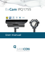
1
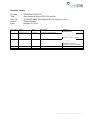
ExCam IPQ1755 User manual Content 1 Introduction .............................................................................................................. 5 2 Document overview ................................................................................................. 7 3 Technical Data .......................................................................................................... 8 3.1 3.2 3.3 3.4 3.5 3.6 3.7 3.8 3.9 3.10 3.11 3.12 Parameters of the explosion protection ............................................................... 8 Electrical parameters of the camera .................................................................... 9 Electrical parameters of the heating (optional) .................................................... 9 System cable SKDxx ......................................................................................... 10 Supply cable (optional) ...................................................................................... 10 Sensor ............................................................................................................... 11 Processor .......................................................................................................... 12 Lense ................................................................................................................ 12 Streaming .......................................................................................................... 12 Parameterization ............................................................................................... 12 Network ............................................................................................................. 13 Other technical data .......................................................................................... 13 4 Safety guidelines .................................................................................................... 16 5 Illustration of the model key .................................................................................. 16 6 Commissioning ...................................................................................................... 18 6.1 6.2 Step 1: Installation ............................................................................................. 18 Step 2: Electrical connection ............................................................................. 18 6.2.1 6.2.2 6.2.3 6.3 6.4 Testing of the status LED .................................................................................. 25 Step 3: Adjusting the lens .................................................................................. 25 6.4.1 6.4.2 6.4.3 6.4.4 6.4.5 7 Potential equalization ............................................................................................................... 19 Connection and protection ....................................................................................................... 20 Tests prior to switching on voltage .......................................................................................... 24 Work preparation ..................................................................................................................... 27 Opening the pressure-resistant housing .................................................................................. 27 Removing / inserting an SD storage card ................................................................................ 30 Hardware Reset ....................................................................................................................... 31 Closing of the pressure-resistant housing ............................................................................... 33 Network access and visualization ........................................................................ 35 7.1 7.2 7.3 Browser Support................................................................................................ 35 Assigning the IP address ................................................................................... 36 Password / Identification ................................................................................... 37 8 Maintenance / Servicing / Alterations ................................................................... 38 9 Repairs and Maintenance ...................................................................................... 38 10 Disposal / Recycling ........................................................................................... 38 11 Drawings.............................................................................................................. 39 12 Notes .................................................................................................................... 42 Doc.-ID: 141023-PT08BA-TG-ExCam IPQ1755 series_en_rev.01, Seite 2 von 44 Table of Figures Figure.1.1 – ExCam IPQ1755 with wall mount bracket and roof ....................................... 6 Table 5.1 – Model key ..................................................................................................... 16 Figure 6.1 – ExCam IPQ1755 potential equalization ....................................................... 19 Table 6.1 – Potential equilization ..................................................................................... 19 Figure 6.2 – Cable gland and supply cable ..................................................................... 20 Figure 6.3 – ExCam IPQ1755 T08-VA2.2.K1.BOR-B-XXX-K-N ...................................... 20 Figure 6.4 – ExCam IPQ1755 T08-VA2.2.K1.BOR-B-XXX-P-N ...................................... 21 Figure 6.5 – ExCam IPQ1755 T08-VA2.2.K1.BOR-B-XXX-P(K)-L(L) ............................. 21 Table 6.2 – Pin assignment SKDxx and plug contact RJ45 ............................................. 22 Figure 6.6 – RJ45 Contact assignment ........................................................................... 23 Figure 6.7 – SKD01 Pin assignment ................................................................................ 23 Table 6.3 – Pin assignment supply cable ........................................................................ 24 Table 6.4 – Status and control LED ................................................................................. 25 Figure 6.8 – Zoom and focus of the ExCam IPQ1755 ..................................................... 25 Abb.6.9 – Advanced control functions of the ExCam IPQ1755........................................ 26 Table 6.5 – Lens data ...................................................................................................... 26 Figure 6.10 – Removing the protection roof_1................................................................. 28 Figure 6.11 – Removing the protection roof _2................................................................ 28 Figure 6.12 – Opening the ExCam IPQ1755 ................................................................... 29 Figure 6.13 – ExCam IPQ1755 installation components ................................................. 30 Figure 6.14 – SD card slot ............................................................................................... 30 Figure 6.15 – Control button ............................................................................................ 32 Figure 6.16 – Status display ............................................................................................ 32 Figure 7.1 – Axis IP Utility................................................................................................ 36 Figure.10.1 – Dimensions of the T08 ExCam IPQ1755 with K1 flange ........................... 39 Figure 10.2 – Dimensions of the T08 ExCam IPQ1755 with K2 flange ........................... 40 Figure 10.3 – Dimensions of the T08 ExCam IPQ1755 accessories ............................... 41 Doc.-ID: 141023-PT08BA-TG-ExCam IPQ1755 series_en_rev.01, Seite 3 von 44 Revision history T08 ExCam® IPQ1755 User manual ExCam® IPQ1755 type 08 141023-PT08BA-TG-ExCam IPQ1755 series_en_rev.01 Thiemo Gruber October 23, 2014 Product: Title: Doc. -Id. Author: Date: Freigabe EX Beauftragter Rev.- Index Datum Name Bemerkung 0 October 23, 2014 T. Gruber Compilation of the document Reviewed and approved October xx, 2014 – S. Seibert 1 December 05, 2014 S.Seibert Revision and approval Reviewed and approved December 05, 2014 – S. Seibert Doc.-ID: 141023-PT08BA-TG-ExCam IPQ1755 series_en_rev.01, Seite 4 von 44 1 Introduction The ExCam IPQ1755 is a camera (type 08) manufactured by SAMCON Prozessleittechnik GmbH, equipped with a light sensitive motor zoom and fast autofocus. Due to the high performance of the ExCam IPQ1755 it disposes of a broad application spectrum within the industrial process observation or in the security sector regarding the surveillance of personnel as well as machine operations. Because of to the combination of a high-resolution CMOS sensor with a 10-fold optical zoom, this network camera is particularly suitable when observing objects in greater distance opting for an extremely detailed visualization. The camera is intended for inside as well as outside use, preferably within hazardous areas of the chemical and/or petro-chemical industry, at offshore plants, in mines, and at biogas plants. The ExCam IPQ1755 is suitable for the usage within the Ex zones 1, 2, 21, and 22 including the gas group IIC (all gases, steams, and fogs including acetylene, hydrogen, and carbon disulphide) and the dust group IIIC (conductive dusts and flammable fibrous material), as well as in mining. Within the equipment group I (mining), the camera series can be used in areas with a low risk of mechanical danger. In case the camera is to be used in areas with a high mechanical risk, the optical components (sight glass) have to be protected suitably. Within the equipment group II (all hazardous areas except mining); the ExCam IPQ1755 is without any additional mechanical protection suitable for all areas with a high mechanical risk. Besides for fixed installation, the T08 ExCam series is also certified to be used for mobile applications (hand-held etc.) The Ex-d stainless steel housing allows additional alloys, a powder coating, or coats of varnishes as well as various mechanical accessories, in order to extend the resistance towards extreme environmental conditions (salt water, acid, solar radiation, high mechanical strains etc.). Due to the usage of high-quality PTFE sealings, not only the protection level IP68 is reached but also the chemical resistance is maximized. Doc.-ID: 141023-PT08BA-TG-ExCam IPQ1755 series_en_rev.01, Seite 5 von 44 Figure.1.1 – ExCam IPQ1755 with wall mount bracket and roof Doc.-ID: 141023-PT08BA-TG-ExCam IPQ1755 series_en_rev.01, Seite 6 von 44 2 Document overview T03 ExCam Series: T08 ExCam Series: ATEX (For areas in hazard of gas and dust explosions) ATEX/ IECEx (For areas in hazard of gas and dust explosions) - EX Installation Manual - EC Declaration of Conformity - ATEX EC Type Examination - Manufacturer‘s declaration (EN 60079-14) - EX Installation Manual - EC Declaration of Conformity - ATEX EC Type Examination - IECEx EC Type Examination - Manufacturer‘s declaration (EN 60079-14) ExCam vario: - User Manual - Datasheet - Technical drawings ExCam miniZoom: - User Manual - Datasheet - Technical drawings ExCam niteZoom: - User Manual - Datasheet - Technical drawings ExCam maxiZoom: - User Manual - Datasheet - Technical drawings ExCam IP: - User Manual - Datasheet - Technical drawings ExCam vario: - User Manual - Datasheet - Technical drawings ExCam miniZoom: - User Manual - Datasheet - Technical drawings ExCam niteZoom: - User Manual - Datasheet - Technical drawings ExCam maxiZoom: - User Manual - Datasheet - Technical drawings ExCam IPM3014: - User Manual - Datasheet - Technical drawings ExCam HD: ExCam IP135x Serie: - User Manual - Datasheet - Technical drawings - User Manual - Data sheet ExCam IP1354 - Data sheet ExCam IP1355 - Data sheet ExCam IP1357 - Technical drawings ExCam IPQ1755: - User manual - Datasheet - Technical drawings Doc.-ID: 141023-PT08BA-TG-ExCam IPQ1755 series_en_rev.01, Seite 7 von 44 3 Technical Data 3.1 Parameters of the explosion protection Identification marks according to Directive 94/9/EG: II 2G (zone 1 and 2) II 2D (zone 21 and 22) I M2 Explosion protection (gas): Ex d IIC T6 Gb or Ex d IIC T5 Gb or Ex d IIB T6 Gb or Ex d IIB T5 Explosion protection (dust): Ex tb IIIC T80°C Db IP68 or Ex tb IIIC T95°C Db IP68 or Ex tb IIIB T80°C Db IP68 or Ex tb IIIB T95°C Db IP68 Explosion protection (mining): Ex d I Mb Protection level: IP 68 (IEC /EN 60529) Transportation and storage temperature (EX): Operation temperature (EX): Ambient temperature (EX)1: -60°C…+85°C -60°C…+80°C (T6) -60°C…+85°C (T5) -60°C…+65°C (T6) -60°C…+70°C (T5) Pressure chamber, internal design: V = 1960 cm3 (bto), free cross sectional area for free a free gas flow ≥ 40% (for Ex group IIC according to DIN EN 60079-1: 2008) Nominated body: EC Type Examination: TÜV Rheinland (number 0035) TÜV 14 ATEX 7539 X IECEx TUR 14.0026X Test protocol ATEX: Test report IECEx: Quality Assessment Report: 557/Ex.539.00/14 DE/TUR/ExTR14.0026/00 DE/BVS/QAR14.0006/00 1 Maximum ambient temperature range relevant for explosion protection might deviate to the maximum functional temperature range. For maximum functional temperature range (MTBF) see chapter 2.12 Doc.-ID: 141023-PT08BA-TG-ExCam IPQ1755 series_en_rev.01, Seite 8 von 44 3.2 Electrical parameters of the camera Axis Q1755 Power supply: Reference power: Maximum power input: 3.3 PoE, IEEE 802.3af class 3 48 V DC (44...54 V DC) 11.2 W Electrical parameters of the heating (optional) DBK HP05-1/04-24 Power supply: Reference power: Maximum power input: Typ L (TAMB ≥ -30°): Typ LL (TAMB ≥-60°C): 12…30 V DC 24 V DC Depending on ambient temperature/ PTC* characteristics (*P = K x A x T (K = 5.5 W/m2) Max. 20 W (1 x heating element HP05) 12.2 W continuous rating at -30° C (inrush current peak > 2000 mA, typical „inrush“ duration < 120 s) Max. 40 W (2 x heating elements HP05) 26.8 W continuous rating at -60° C (inrush current peak > 4000 mA, typical „inrush“ duration < 120 s) Temperature controller B005-MQT8K 5X/C Function: Opening/ closing of the heating load power circuit (bi-metal switch, heating element type LL are initiated individually and autarkic, 2x B005-MQT8K) Switch-on temperature: 5° C (±3 K) Hysteresis: 5…8 K Nominal voltage: 12…48 V DC Switched current: 1.3 A (permanent load) Contact resistance: < 70 mΩ Doc.-ID: 141023-PT08BA-TG-ExCam IPQ1755 series_en_rev.01, Seite 9 von 44 3.4 System cable SKDxx Description: Shealth color: Routing: Outer diameter: Bending radius: Cable: Characteristics: Interface: 3.5 Data transfer and power supply of the camera module (DIN EN 60079-14 conform) Green (GN), similar RAL6018 via cable gland „1“ Ex IIB: ADE 4F MsNi Type5-M20x1.5 Ex IIC: PXSS2K-M 20 x 1.5 (cable gland with integrated pressure stop / compound) 8.7 mm ± 0.3 mm 100 mm 4 x 2 x AWG22/1 CAT.6a PUR halogen free, flame retardant, UV resistant, chemical resistance, shielded (see www.samcon.eu; data sheet SKD01) P version: RJ-45 (EIA/TIA-568B) e.g. Weidmueller IE-PS-RJ45-FH-BK, Phoenix Contact VS-08-RJ45-5-Q/IP20 etc. 10BASE-T/100BASE-TX PoE K version: 8x single pin twisted pair (solid conductor 0.64 mm2, about 5 mm stripped) 1x shield (Cu braid 2.5 mm2, ferules) 10BASE-T/ 100BASE-TX PoE Supply cable (optional) Description: Shealth color: Routing: Outer diameter: Bending radius: Power supply of the heating elements including temperature controller, Ölflex® Robust 2102 (DIN EN 60079-14 conform) Black (BK) matt, similar RAL9005 via cable gland „2“ Ex IIB: ADE 4F MsNi Type5-M 20 x 1.5 Ex IIC: PXSS2K-M 20 x 1.5 (cable and cable gland with integrated pressure stop/ compound) 7.6 mm 15 x outer diameter (for occasional movement) 4 x outer diameter (for fixed installation) 2 Further cables available upon request, e.g. „Ölflex® Petro FD 865 CP“ (high resistance against oil and drilling liquids) or „XPLE Armoured 3 x 2.5“ (extremely robust, particularly designed for offshore environments) Doc.-ID: 141023-PT08BA-TG-ExCam IPQ1755 series_en_rev.01, Seite 10 von 44 Conductor design: Characteristics: Isolation: Nominal voltage U0/U: Test voltage: Interface: 3.6 2 x 2.5 mm2, litz wire made of blank fine wire copper according to VDE 0295 Kl.5 / IEC 60228 Cl.5, no earth conductor, pins twisted in layers, pin isolation made of modified PP Special TPE halogen free, flame resistant, UV and ozone resistant, high chemical resistance, heat and cold resistance, reduced outer diameter > 20 GΩ x cm 300/500 V AC/DC 4000 V P version: N/A or upon request K version: 2 x 2.5 mm2 Cu litz wire (BK/ BK) with ferule, sheath about 10 cm stripped and furnished with bend relief / shrink tubing Sensor Axis Q1755 Type: Effective sensor resolution: Light sensitivity: 1/3‘‘ RGB CMOS, progressive scan HDTV 1080i 1920x1080 px, HDTV 720p 1280 x 720 px (16:9) Color: 2.0 lux at 30 IRE, F1.8 BW: 0.2 lux at 30 IRE, F1.8 Doc.-ID: 141023-PT08BA-TG-ExCam IPQ1755 series_en_rev.01, Seite 11 von 44 3.7 Processor Type: Storage: 3.8 Lens Type: Angle of view: Focus range: Shutter time: Zoom: 3.9 f = 5.1 – 51.0 mm, F1.8 - 2.1, auto focus, automatic day/night operation, M37 x 0.75 connecting thread for an optional lens adapter 48.1°-5.1° horizontally, 27.1° - 2.9° vertically /(16:9) 0.1 m - infinite (wide) 0.8 m - infinite (tele) 1/10000 s to 1/2 s @50/60Hz net frequency 10-fold optical zoom, 12-fold digital, 120-fold maximum Streaming Video compression: Frame rate: Functions: 3.10 ARTPEC-3 256 MB RAM, 128 MB Flash H.264 (MPEG-4 Part 10/AVC), Motion JPEG 30 fps/ H.264 at all resolutions 25 fps/ Motion JPEG at all resolutions Multiple, individually configurable streams in H.264 and Motion JPEG, controllable frame rate and bandwidth VBR/CBR H.264 Parameterization Image settings: Intelligent Video: Event triggers: Compression, color, brightness, sharpness, contrast, white balance, exposure control, backlight compensation, picture rotation: 0°, 90°, 180°, 270° including Corridor Format™, text and image overlay, privacy mask, mirroring of images Video motion detection, active tampering alarm, audio recognition, gate keeper Video motion detection, active tampering alarm, audio recognition, temperature, external signals Doc.-ID: 141023-PT08BA-TG-ExCam IPQ1755 series_en_rev.01, Seite 12 von 44 Event actions: Local storage: 3.11 Network Security: Supported protocols: 3.12 File upload: FTP, HTTP; E-mail notification, HTTP and TCP, activation of external outlets; 96 MB pre and post alarm video buffering SD/ SDHC – internal slot for storage cards of up to 64GB (16GB SDHC included in delivery scope) Password protection, IP address filtering, HTTPS encryption, IEEE 802.1X network access control, digest authentication, user access log IPv4/v6, http, HTTPS, QoS Layer 3 DiffServ, FTP, CIFS/SMB, SMTP, Bonjour, UPnP, SNMPv1/v2c/v3 (MIB-II), DNS, DynDNS, NTP, RTSP, RTP, TCP, UDP, IGMP, RTCP, ICMP, DHCP, ARP, SOCKS Other technical data Permitted ambient temperature (MTBF)3: Protection level EN 60529/IEC 529: -10 °C … +40 °C (Type N) -30 °C … +40 °C (Type L) -60 °C … +40 °C (Type LL) IP 68 Test conditions: 24 h/ 3 m water column at 5° C. An additional mechanical protection against water jets is recommended 3 Functional temperature range concerning the operational temperature range of the installed components according to manufacture declarations (MTBF – meantime ration duration between failures). For ambient temperature ranges relevant for explosion protection (ATEX, IECEx) see chapter 2.1 – Explosion protection) Doc.-ID: 141023-PT08BA-TG-ExCam IPQ1755 series_en_rev.01, Seite 13 von 44 Housing material4 (EN 10027-2): (flameproof enclosure) Stainless steel MNo.: 1.4301 (X5CrNi18-10), AISI 304 (V2A) – Standard Stainless steel MNo.: 1.4305 (X8CrNiS18-9), AISI 303 – Standard Stainless steel MNo.: 1.4401 (X5CrNiMo17-12-2), AISI 316 (V4A) – optional Stainless steel MNo.: 1.4404 (X2CrNiMo17-12-2), AISI 316L (V4A) – optional Edelstahl MNo.: 1.4571 (X6CrNiMoTi17-12-2), AISI 316Ti, (V4A) – optional Additional housing materials: Zinced spring steel MNo.: 1.0330, PTFE with glass microbeads (GYLON® Style 3504 blue), silicone-coating (Silcoset 105 incl. Cure Agent 28), VMQ (silicone), polyester (acetone resistant), titan (Ti22) Sight glass material: Borosilicate glass (Ilmadur 10/ I-420) Additional internal materials: Aluminum die cast, zinced (protection housing of the camera module), polyamid isolatores, mounting adapter made of aluminum (AlMgSi), zinced steel metal sheet, plastics, PUR etc. Weight (without accessories): 7100 g (with „K1“ cable gland flange) 8200 g (with „K2“ cable gland flange) 1600 g (wall mount bracket and hood) Weight accessories: Dimensions housing (BxHxT)5: 113.0 mm x 138.5 mm x 260.2 mm (K1 flange) 113.0 mm x 138.5 mm x 276.0 mm (K2 flange) Dimensions with accessories (wxhxd)6: 135.0 mm x 238.0 mm x 413.0 mm 4 The available stainless steel materials dispose of different specific characteristics such as mechanical and chemical resistance. It is possible to optimize the corrosion behavior in highly acidiferous environments or at offshore applications by selecting the applicable housing material. An electro-polished or powder-coated surface in various RAL colors (standard: RAL7035) is possible. 5 Dimension stainless steel housing T07 VA2.2 with pin and without cable gland and external accessories. For additional / detailed dimensions see chapter 10 – technical drawings 6 Dimensions camera housing T07 VA2.2 with wall mount bracket and roof (pointing forward) Doc.-ID: 141023-PT08BA-TG-ExCam IPQ1755 series_en_rev.01, Seite 14 von 44 Fitting of the flame proof gap preventing the transmission of ignition (cylinder) (EX) T07 VA2.2: Media resistance7 (excerpt): 7 Nominal diameter: 91 mm Clearance fit: H8 f7 (DIN ISO 286) Tolerance: -71µm…+54µm Gap length: > 12.5 mm Gap width: < 0.15 mm Average surface finish: Ra ≤ 6.3 μm Acetone, alcohol, acetylene, ammoniac, aniline, benzol, butane, chloride, pressurized water, pressurized air, ethane, crude oil, fluoride, glycerin, sea water, methane, oils, phosphoric acid, propane etc. Additional media resistance as well as well as validation of chemical resistances possible upon request Doc.-ID: 141023-PT08BA-TG-ExCam IPQ1755 series_en_rev.01, Seite 15 von 44 4 Safety guidelines Please observe the safety guidelines indicated in der EX installation manual of the T08 ExCam series! 5 Illustration of the model key The following model options are currently available for the ExCam IPQ1755: Ex product name Model options 2) 1) Type Housing 3) combination Gas expl. 4) group Cable length/m 5) SKDxx/SKLxx cable 6) termin. ExCam IPQ1755 T08T08T08T08T08T08T08T08T08T08T08T08T08T08T08T08- VA2.2.K1.BORVA2.2.K1.BORVA2.2.K1.BORVA2.2.K1.BORVA2.2.K2.BORVA2.2.K2.BORVA2.2.K2.BORVA2.2.K2.BORVA2.2.K1.BORVA2.2.K1.BORVA2.2.K1.BORVA2.2.K1.BORVA2.2.K1.BORVA2.2.K1.BORVA2.2.K1.BORVA2.2.K1.BOR- BBCCBBCCBBCCBBCC- 005005005005005005005005005005005005005005005005- KN PN KN PN KN PN KN PN KL PL KL PL KLL PLL KLL PLL Table 5.1 – Model key ExCam IPQ1755 ExCam IPQ1755 Tempera7) ture range 1) ExCam IPQ1755 = Functional camera description of the ExCam IPQ 1755. Distinctive characteristics are, for example: Sensor resolution, light sensitivity, angle of view, iris control, zoom characteristics (wide/tele, optical/digital, motor driven/ varifocal) etc. 2) T08 = Certified production type, device designation „T08 ExCam series“, EC type examination: „TÜV 14 ATEX 7539 X“ and „IECEx TUR 14.0026X“ 3) VA2.2.K1.BOR = T07 Ex d housing with large diameter (ØVA=113 mm) and large sight glass (QBOR=72 mm) 4) VA2.2.K1.BOR = VA2.2.K1.BOR = VA2.2.K2.BOR = T07 housing with maximum body length (lR = 238 mm) K1 cable gland flange (straight cable gland(s)) K2 cable gland flange (orthogonal cable gland) Doc.-ID: 141023-PT08BA-TG-ExCam IPQ1755 series_en_rev.01, Seite 16 von 44 5) VA2.2.K1.BOR = Borosilicate sight glass (Standard execution, for video cameras within visible spectral range: λ = 350…2000 [nm] and near Infra red (NIR), not suitable for thermographic applications) Alternatively: Germanium (GER) / zinc sulfide (ZnS Flir) B= Explosion group IIB/ IIIB (Standard execution. Suitable for all gases except hydrogen, acetylene, carbon disulfide, flammable fibrous material and nonconductive dusts Explosion group IIC/ IIIC (Optional execution. Suitable for all gases, flammable fibrous materials and conductive dusts) C= 6) 7) 8) 005 = Length of the connection line in meter at delivery. The standard cable length is 5 m (minimum/maximum cable length: 001…100 [m]) K= Terminal block execution (standard) 2, SKDxx: 8 x single pin twisted pair (solid conductor 0.64 mm 2 about 5 mm stripped) 1x shield (Cu braid 2.5 mm , ferules) Supply: („Ölflex Robust 2102 x 2.5 mm2 Cu litz wire with ferule, sheath about 10 cm stripped and furnished with bend relief/shrink tubing P= Plug termination (optional) SKDxx: RJ-45 network plug (heavy duty), AWG 26-22. Type Weidmueller IE-PS-RJ45-FH-BK, pin assignment according to EIA/TIA-568B Supply: („Ölflex Robust 210“) n.a. / upon request N= L= LL = Normal ambient temperature range (MTBF): Low ambient temperature range (MTBF): Lowest ambient temperature range (MTBF): TAMB_N: -10 … +40 [°C] TAMB_L: -30 … +40 [°C] TAMB_LL: -60 … +40 [°C] Doc.-ID: 141023-PT08BA-TG-ExCam IPQ1755 series_en_rev.01, Seite 17 von 44 6 Commissioning Attention! Please observe the national regulations regarding security, installation, and accident prevention (e.g. DIN EN 60079-14) as well as the safety guidelines described in this user manual and the EX installation manual! Attention! Please observe the installation and commissioning advices described in the Ex installation manual! 6.1 Step 1: Installation Install the ExCam® IPQ1755 at the desired location. Mounting options, accessories, as well as safety guidelines are described in the EX installation manual of the ExCam ® series. 6.2 Step 2: Electrical connection Attention! The electrical connection of the equipment must be executed by qualified personnel only! Attention! It is mandatory that the housing of the ExCam® Series has to be grounded via a PE-connection! Attention! The minimum cable length of the connection line must not be less than one meter! The connection cable has to be laid in a protected manner! Attention! Please observe the national regulations regarding security, installation, and accident prevention (e.g. DIN EN 60079-14), as well as the safety guidelines described in this user manual and the EX installation manual! Doc.-ID: 141023-PT08BA-TG-ExCam IPQ1755 series_en_rev.01, Seite 18 von 44 The ExCam ® IPQ1755 is delivered with an electrical connection cable type SKDxx (System Kabel Digital) and optional with an additional supply cable e.g. of the type „Ölflex® Robust 210“.The maximum cable length is 100 m (depending on electromagnetic tolerance) and can be determined individually to reflect the particular customer specifications. The minimum cable length is 1 meter. The ExCam® IPQ1755 is manufactured with a pigtail reflecting the desired cable length. Any electro-technical work inside the camera’s flameproof enclosure done by the user is prohibited. Depending on the model option, the ending of the camera’s cable connection is either stripped to the blank Cu conductors or furnished with a plug. 6.2.1 Potential equalization Figure 6.1 – ExCam IPQ1755 potential equalization The potential equalization / earthing of the camera housing is mandatory in order to avoid electrostatic charging and hence spark generation. The screw terminal at the lower right hand side of the housing’s rear side is intended for that purpose (q.v. figure 6.1). The profile of the potential equalization has to reflect the national grounding instructions (min. 4mm2). Connection table: Potential PE Color (IEC 60757) GN/YE Profile 2 4 mm (fix) Comment Screw terminal: Slotted screw M4 x 0.7 (DIN 84) with washer Ø 9 mm (DIN 125A) Table 6.1 – Potential equilization Doc.-ID: 141023-PT08BA-TG-ExCam IPQ1755 series_en_rev.01, Seite 19 von 44 6.2.2 Connection and protection Cable gland 2 (optional: Ölflex Robust 210 - supply heating elements) Cable gland 1 (SKDxx digitale video stream / performance of the camera modules) Figure 6.2 – Cable gland and supply cable Figure 6.3 – ExCam IPQ1755 T08-VA2.2.K1.BOR-B-XXX-K-N Doc.-ID: 141023-PT08BA-TG-ExCam IPQ1755 series_en_rev.01, Seite 20 von 44 Figure 6.4 – ExCam IPQ1755 T08-VA2.2.K1.BOR-B-XXX-P-N Figure 6.5 – ExCam IPQ1755 T08-VA2.2.K1.BOR-B-XXX-P(K)-L(L) The green patch cable SKDxx disposes of 8(+1) conductors used for the data transfer with other network devices as well as to power the camera. In order to guarantee the power supply (Power Device, PD) of the ExCam IPQ1755 (power device, PD) a Power-over-Ethernet component (Power Sourcing Equipment, PSE) has to be available at the connecting side (e.g. a PoE Switch, a PoE Injector, or Midspan) which meets the specification IEEE 802.3af of the power class 3 (6.49– 12.95W/ 26-30mA). A 100 Mbit Ethernet Connection (100BASE-TX) is used for the ExCam IPQ1755 data transfer. Doc.-ID: 141023-PT08BA-TG-ExCam IPQ1755 series_en_rev.01, Seite 21 von 44 In case the camera disposes of a plug, (figure 6.4), it has to be plugged into the RJ45 PoE slot of the network device. Due to the design, a faulty connection or pin assignment is not possible. The network device can already be supplied with power, prior to connecting it to the camera, hence there is no „power ON“ priority which has to be observed. In case the ExCam IPQ1755 disposes of a terminal block termination, the correct connection of the individual pins in accordance with EIA/TIA-568B has to be observed (q.v. table 6.2). Generally, the pins of the same color code are connected. Attention: The general specification for PoE allows different operation modes for PDs (ExCam IP1354, ExCam IP1355, ExCam IPQ1755 etc.): Mode A (end span): This is usually used by switches; the supply voltage is executed as phantom power on the data lines. Both polarities are possible. Mode B (mid span): This is usually used by PoE injectors; the power supply and protocol transfer is executed on separate pins (plug / pin contact 4.5 is the positive pole and 7.8 is the negative pole). The T08 ExCam series supports both modes and the used power source (PSE) determines the mode. For executing a reboot, it is possible to separate the ExCam IPQ1755 from the network and to switch it on again while in operation or in interaction with a visualization system (hot plugging). Attention: „Hot plugging“ as well as the connection and separation of the data and power cable SKDxx with/of network devices and terminal blocks under power is only allowed within the safe area (non-hazardous atmosphere)! The pin assignment of the SKDxx according to EIA/TIA-568B standard for 100BaseTX with PoE (IEEE 802.3af) is done as follows: Pin / Potential Mode A Mode B Tx+ / PoE ±48 VDC Tx+ Tx- / PoE ±48 VDC TxRx+ / PoE GND Rx+ n.a. PoE +48 VDC n.a. PoE +48 VDC Rx- / PoE GND Rxn.a. PoE GND n.a. PoE GND shield/ GND (complete conductor bunch) shield (single, twisted pair pins) Color SKDxx (IEC60757) WH / OG OG WH / GN BU WH / BU GN WH / BN BN BK n.a. Plug / pin contact (TIA-568B) 1 2 3 4 5 6 7 8 9 Cross section area Remarks 2 0.64 mm 2 0.64 mm 2 0.64 mm 2 0.64 mm 2 0.64 mm 2 0.64 mm 2 0.64 mm 2 0.64 mm 2 2.5 mm Solid conductor Solid conductor Solid conductor Solid conductor Solid conductor Solid conductor Solid conductor Solid conductor Shield braid of tinned copper wires Ø=0.13 mm (AWG 36) n.a. / 10 n.a. Aluminum synthetic strapp, twisted Table 6.2 – Pin assignment SKDxx and plug contact RJ45 Doc.-ID: 141023-PT08BA-TG-ExCam IPQ1755 series_en_rev.01, Seite 22 von 44 9 Figure 6.6 – RJ45 Contact assignment Particularly in EMC critical environments, it is important to earth the shield at the terminal block side (q.v. figure 6.3 – pin with black shrink tubing and blue ferule). 5 1 4 2 8 6 7 9 (shield/ GND) 3 10 (shield) Figure 6.7 – SKD01 Pin assignment In case the ExCam IPQ1755 is supplied via a PoE capable device, an additional safeguarding of the power supply is not necessary. The power supply is executed by the PoE network device via an electronic with intelligent set-up. The camera as well as the connection is permanently monitored in order to avoid any failure or defects in case of a short-circuit fault. For a camera with terminal block execution, it is possible to operate the camera either with a PoE capable network device or with a separate 48 V DC power supply (supply voltage and network streams are self-sustaining). In this event an adequate supply safeguarding has to be dimensioned. Recommended is a 300 mA medium time lag fuse. Doc.-ID: 141023-PT08BA-TG-ExCam IPQ1755 series_en_rev.01, Seite 23 von 44 If the Ex CCTV application calls for a separate 48 V DC supply voltage, the wire/pin assignment has to reflect Mode B operation mode (q.v. table 6.2)! If the camera is equipped with a heating (type L or type LL), a second power supply with a separate supply protection at the „L+“ has to be available. Standardly the supply is carried out via the supply cable Ölflex® Robust 210 (cable gland 2, q.v. figure 6.2 and 6.5). Connection assignment and supply protection according to table 6.3. L+ / 1 Color „Ölflex Robust 210“ (IEC60757) BK L- / 2 BK Potential/ Pin no. Cond. design Voltage 2 2.5 mm litz wire 2 2.5 mm litz wire +24 VDC 0 VDC / GND Maximum power input / protection (type L) 20 W / fuse (L+) 2000 mA -T- time lag (high inrush current!) Maximum power input / protection (type LL) 40 W / fuse (L+) 4000 mA -T- time lag (high inrush current!) Table 6.3 – Pin assignment supply cable 6.2.3 Tests prior to switching on voltage Attention! Prior to commissioning, all tests as indicated by the national regulations have to be executed. In addition, it is mandatory that the proper functioning of the operating device in accordance with this user manual and all other applicable regulation has been executed. Attention! Incorrect installation and operation of the camera may lead to a loss of warranty! Doc.-ID: 141023-PT08BA-TG-ExCam IPQ1755 series_en_rev.01, Seite 24 von 44 6.3 Testing of the status LED Through the sight glass, the status LED is visible. Prior to finishing the installation process and accessing the camera via the web interface, the proper functioning of the camera should be tested. The booting process of the ExCam IPQ1755 may take up to one minute. Additional LEDs for checking network activities or the bandwidth are only visible when the housing is open. The status of the applicable network camera as reflected by the LED indicators is as follows: Status LED Operating mode Color Green Yellow Red Usage of the focus assistant Remarks At normal operation, a constant green light shows Note: It is possible to configure the status LED in such a manner that in normal operation it is not illuminated or only blinks when the camera is accessed It is illuminated permanently when the camera is turned on as well as when the camera is set back to default settings In case of an activation failure the light blinks slowly n.a. Table 6.4 – Status and control LED 6.4 Step 3: Adjusting the lens Adjusting the lens of the ExCam IPQ1755 is exclusively done via the web interface or the visualization software. Mechanical adjustments at the motor zoom lens by the user are not possible. Via the web interface’s control function, it is possible to manually configure the focus as well as the tele range, (q.v. figure 6.8). In order to activate the „Auto focus“ as well as advanced functions, the „Control panel“ can be used (q.v. figure 6.9). Here, back light compensation, the infrared cut filter, and the iris can be controlled. Figure 6.8 – Zoom and focus of the ExCam IPQ1755 Doc.-ID: 141023-PT08BA-TG-ExCam IPQ1755 series_en_rev.01, Seite 25 von 44 Figuer 6.9 – Advanced control functions of the ExCam IPQ1755 IP 1354 Lens type Lens Aspherical technology Focal distance Horizontal angle of view Iris control MOD (Minimum object distance) IP 1355 IP1357 Varifokal, IR-korrigiert, CS mount IPQ1755 Motor zoom 10x optical, M37 x 0.75 connecting thread Auto focus, F1.8 – 2.1/ f5.1 – 51 mm DC-iris, F1.2/ 2.8 – 8 mm P-Iris, F1.2/ 2.8 – 8 mm P-Iris, F1.2/ 2.8 – 8 mm No No No No 2.8 – 8 mm 100°(wide) – 34°(tele) 2.8 – 8 mm 109°(wide) – 39°(tele) Precisionautomatic 2.8 – 8 mm 92°(wide) – 32°(tele) Precisionautomatic 5.1 – 51 mm 48.1°(wide) – 5.1°(tele) Automatic 0.30 m Day/Night automatic operation 0.10 m Table 6.5 – Lens data Information! If not determined differently, the default setting for the ExCam® IPQ1755 is pre-configured to reflect maximum sensor resolution (HDTV 1080i, q.v. chapter 3.6) and low compression (high picture quality, high network bandwidth). Also, the camera is set to „wide“ range and the auto focus is deactivated. If desired, we customize the settings of the ExCam IPQ1755 to net existing network and hardware requirements. Doc.-ID: 141023-PT08BA-TG-ExCam IPQ1755 series_en_rev.01, Seite 26 von 44 6.4.1 Work preparation Attention! Please carry out any preoperational work carefully and in accordance with the applicable regulations Attention: Note: Depending on the zone classification, it might be necessary to obtain a work permit/clearance! When adjusting the camera settings potentially explosive atmosphere must be avoided by any means! To allow the camera delivering the best picture quality, please consider the lighting conditions, the object distance and size, the angle of view as well as the minimum object distance for focusing when selecting the installation place. 6.4.2 Use appropriate tools Make sure you have a secure foothold Avoid static charge Opening the pressure-resistant housing Opening the pressure resistant housing (DIN EN 60079-1: 2008) of the ExCam IPQ1755 is only allowed in case the SD storage card has to be removed or replaced or that a „Hardware Reset“ of the camera module is necessary. All additional mechanical and electrical interventions inside the Ex-d housing by the user are not allowed and are only to be executed by SAMCON Prozessleittechnik. After the completion of the work, the pressure resistant housing has to be closed to be explosion-proof again. Please be very careful and follow thoroughly the steps of this manual. „WARNING – DO NOT OPEN IN HAZARDOUS AREA“ Note: Depending on the zone classification, it might be necessary to obtain a work permit/clearance! Even after disconnection of the voltage, it is mandatory to avoid potentially explosive atmosphere when opening the camera housing (de-installation of the camera and execution of the work within the safe area (non EX)! Doc.-ID: 141023-PT08BA-TG-ExCam IPQ1755 series_en_rev.01, Seite 27 von 44 In case the T08 ExCam IPQ1755 is equipped with a protection roof, it has to be removed first. To do so, loosen the four 8 mm lens head screws M4*0.7 at the front and back of the bracket (figure 6.10 and figure 6.11). Figure 6.10 – Removing the protection roof_1 Figure 6.11 – Removing the protection roof _2 To open the enclosure (T07 VA2.2) of the ExCam IPQ1755, loosen the four hexagon socket screws (DIN 912/ ISO 4762) located at the cable gland flange of the stainless steel housing, including the washer springs (DIN 127 A) (q.v. figure 6.10). Avoid skin or clothing contact with the screw threads as they dispose of LOCTITE ® 243™ (chemical basis: Dimethacrylatester). It is used to protect the screws from losing due to shocks, vibrations, but also for sealing purposes. It is not allowed to open the sight glass flange! Doc.-ID: 141023-PT08BA-TG-ExCam IPQ1755 series_en_rev.01, Seite 28 von 44 Figure 6.12 – Opening the ExCam IPQ1755 Pull out very carefully the lead flange in a straight manner, ensuring that the board modle does not tilt. Due to the created lower pressure, this might require some additional effort. The cylindrical clearance fit (H8f7 - DIN ISO 286) of the body as well as of the flange components must not be tilted as this runs the risk of damaging the flame proof gap preventing the transmission of ignition (DIN EN 60079-1:2012)! Attention: The mounting adapter with the heating module, the temperature controller, the camera module and the optical module are fixed to the cable gland flange. Beware also of tilting and work very carefully to avoid damaging the components! Avoid skin and clothing contact with the cylindrical fit, the surface is treated with lubrication paste (oleaginous) to protect the surface against frictional corrosion and mechanical strain. When opening the housing, make sure not to damage or to pollute the Gylon sealing (blue)! The sealing is not firmly attached to the cable and supply flange and isonly fixed by the means of the screw connections. Attention! Beware not to damage the surface of bore hole and shaft (fit) at the flame proof gap preventing the transmission of ignition. Attention! Please make sure not to damage housing sealings and to keep them clean Doc.-ID: 141023-PT08BA-TG-ExCam IPQ1755 series_en_rev.01, Seite 29 von 44 Temperature controler MQT8K Axis Q1755 IP camera Terminal Phoenix MT1.5 Heating element DBK-HP05 Figure 6.13 – ExCam IPQ1755 installation components 6.4.3 Removing / inserting an SD storage card The ExCam IPQ1755 is delivered with a 16GB SDHC storage card. Stored video files can be viewed or deleted via the web Interface and are also available on the download list (http://....). The videos stored on the storage card can also be accessed via an FTP server within the network (ftp://....). If it should become necessary to exchange the storage card, please use an empty one which has been pre-formatted with an „ext4“ or „vFAT“ data system. The storage card slot is situated on the back of the camera module (q.v. figure 6.14). SD storage card slot Figure 6.14 – SD card slot Doc.-ID: 141023-PT08BA-TG-ExCam IPQ1755 series_en_rev.01, Seite 30 von 44 Please pay attention when inserting / removing the storage card not to damage the terminals and the connection cable! Do not bend the mounting adapter as otherwise this may affect the optical axis of the camera! When touching electrical components, potential equalization (grounding of the body) has to be observed (carry a PE wristband etc.)! 6.4.4 Hardware Reset In order to reset all parameters, including the IP address, of the ExCam IPQ1755 to default settings, a hardware reset has to be carried out. The parameters can be reset via the web surface or also manually. If the camera is not accessible in the network, the reset has to be carried out manually. To do so, please follow the steps below: 1. Disconnect the camera module (Axis Q1755) from the power supply 2. Hold the control button pressed (q.v. figure 6.15) while, at the same time, switching on the power supply (PoE) 3. Keep the control button pressed until the status light turns yellow (figure 6.16). This may take up to 15 seconds 4. Release the control button. As soon as the control light is green, the ExCam IPQ1755 has been reset to Axis default settings. This may take up to one minute. The IP address is now: 192.168.0.90 (subnet 255.255.255.0). 5. It is now possible to reassign a new IP address as well as new password. If the hardware reset does not deliver the desired results or if the camera displays severe conflicts or does not function properly anymore (e.g. problems with the browser visualization, freezing of the picture, or control commands are not carried out anymore), it might be necessary to install the latest version of the firmware (q.v. chapter 7.4) Doc.-ID: 141023-PT08BA-TG-ExCam IPQ1755 series_en_rev.01, Seite 31 von 44 Control button Figure 6.15 – Control button LED status bar Figure 6.16 – Status display Doc.-ID: 141023-PT08BA-TG-ExCam IPQ1755 series_en_rev.01, Seite 32 von 44 6.4.5 Closing of the pressure-resistant housing For closing the housing, please follow, in reversed order, the steps described in the chater 6.4.2 regarding the opening of the housing. Do not use any other screws than those which are part of the delivery scope. For the execution with a „K1“ cable gland, 8 x cylin-der head screws M4 x 0.7 (ISO metric right-hand thread) with a thread length of 12 mm (DIN 912/ ISO 4762, quality 6g) are used. The material of the screw connection is variable, e.g. stainless steel MNo. 1.4301 (A2-70) corresponding to the pressure resistant housing or a titan execution (Ti22) in metallic red. For the execution with a „K2“ cable gland, 7 x cylinder head screws M4 x 0.7 (ISO metric right-hand thread) with a thread length of 30 mm are used. Please check that the bore holes and flameproof joint (cylindrical fit) are clean and intact. Attention! In case the flameproof joint has been damaged mechanically, the housing must not be used anymore! Attention! Do not lock-in any foreign objects inside the housing Please make sure that the disassembled screw locks (washer spring DIN 127A) are reassembled. The Gylon sealing must be intact and has to be reassembled according to the holepattern of the flange. There is no restriction regarding the installation direction of the sealing. If, when closing the housing, it is noted that the surface of the flameproof joint is dirty or not lubricated sufficiently, please clean it with a clean cloth and suitable cleaning detergent. Afterwards, re-lubricate it with a suitable lubrication agent. The screw connection of the flange and housing have to be tightened in crosswise sequence with a torque of 3 Nm Please avoid extensive tightening – this might lead to a torn screw. If the camera does not provide the anticipated results, steps 6.4.2 to 6.4.5 have to be repeated. For the fixed installation of the ExCam IPQ1755, either with a wall mount bracket, with a hinge attachment for sight-glass installations or for the optional installation of a roof, please observe the instructions of the EX installation manual! Doc.-ID: 141023-PT08BA-TG-ExCam IPQ1755 series_en_rev.01, Seite 33 von 44 The T08 ExCam series is certified to be also used for mobile applications (hand-held etc.) The cylinder head screws for the safe connection of the housing body and the flange have to be tightened with a torque of 3 Nm! Doc.-ID: 141023-PT08BA-TG-ExCam IPQ1755 series_en_rev.01, Seite 34 von 44 7 Network access and visualization In the following the most important steps for the initial commissioning of the camera are described. The configuration menu of the web surface allows an intuitive navigation and offers several configuration possibilities. For a comprehensive user manual of the web surface, please refer to the to the Axis user manual which can be found on the provided USB stick or which can be accessed at: ExCam IPQ1755 http://www.axis.com/files/manuals/um_q1755_45216_en_1111.pdf Network access of the ExCam IPQ1755 is supported by most operating systems and browsers. The recommended browsers are Internet Explorer with MS Windows, Safari with Macintosh and Firefox with Windows and additional operating systems. To carry out „video streaming“ via the Microsoft Internet Explorer, installing the “AXIS Media Control” (AMC) is required. The installation request is executed during the initial commissioning. In order to visualize the „H.264“ video streams, QuickTime TM is recommended. For „Motion JPEG“ coded video streams, Java Applet is suggested which requires JVM (J2SE) 1.5 or higher, or JRE (J2SE) 5.0 or higher. At delivery, the ExCam IPQ1755 is set to the applicable net frequency (50Hz or 60Hz). If the camera is used at a location with a differing net frequency, a flickering of the picture might be noticeable, particularly in surroundings with fluorescent tubes. In such a case, the applicable settings have to be carried out within the menu “System Options > Advanced > Plain Config”. 7.1 Browser Support A list with the currently supported web browsers, operating systems, and required addons can be viewed at: http://www.axis.com/techsup/cam_servers/tech_notes/browsers.htm Doc.-ID: 141023-PT08BA-TG-ExCam IPQ1755 series_en_rev.01, Seite 35 von 44 7.2 Assigning the IP address The ExCam IPQ1755 is an Ethernet network camera requiring an IP address to access it. Usually a DHCP server is integrated in most networks which automatically assigns an IP address. In case there is no DHCP server available in the network, the ExCam IPQ1755’s default address “192.168.0.90” (subnet masking 255.255.255.0) is used. With the “AXIS IP Utility“ it is possible to determine the IP address under Windows; the included USB stick contains this application. It is also available for download: http://www.samcon.eu/en/downloads/drivers-software/ In case it is not possible to assign the IP address, it might be necessary to change the firewall settings! The “AXIS IP Utility“ tool automatically recognizes all ExCam devices and displays them. It can also be used to manually assign a static IP address. Please note that the ExCam IPQ1755 network camera has to be installed within the same network segment (physical subnet) as the computer on which the “AXIS IP Utility” tool is executed. For example, the ExCam IPQ1755 network identification is „Axis Q1755“ (q.v. figure 7.1). MAC address and serial number are also determined and displayed so that a non-ambiguous identification is possible. ExCam IP1354 ExCam IPQ1755 ExCam IPM3014 Figure 7.1 – Axis IP Utility Doc.-ID: 141023-PT08BA-TG-ExCam IPQ1755 series_en_rev.01, Seite 36 von 44 7.3 Password / Identification The default user name is: The default password is: root root When a system reset of the equipment has been carried out, please follow the instructions below. In order to allow access to the camera, the password for the standard administrator user „root“ has to be determined. When accessing the camera for the first time, the dialog field „Configure Root Password“ is displayed and the password can be determined there. For security considerations, it is possible to use an encrypted HTTPS-connection requiring an HTTPS certificate (see steps below). For assigning the password via a standard HTTP connection, please just enter the password directly in the dialog window „Configure Root Password“. For using an encrypted HTTPS connection when determining the password, please follow the below steps: 1. 2. 3. 4. 5. 6. 7. Click on the button „Create self-signed certificate“ Enter the desired information and click „OK“. The certificate is issued and the password can be entered. Please note that the entire data transfer of the ExCam IPQ1755 will be encrypted Enter the desired password and repeat it in order to ensure correct spelling. Click on “OK“ to configure that password Enter the username “root“ (it is not possible to delete the default administrator user name „root“) Enter the previously determined password and click on „OK“. In case you have forgotten the password, the ExCam IPQ1755 has to be reset to default settings Click on „Yes“ in order to install AMC (AXIS Media Control). After the completion of the installation, it is possible to view the video streams with the Microsoft Internet Explorer or Mozilla Firefox (administrator rights are required) The page „Live View“ of the ExCam IPQ1755 is now displayed. With the setup link it is possible to open the menu options to allow personal camera settings Doc.-ID: 141023-PT08BA-TG-ExCam IPQ1755 series_en_rev.01, Seite 37 von 44 8 Maintenance / Servicing / Alterations The national regulations concerning the maintenance and servicing of electrical devices within hazardous areas are to be observed. The required maintenance intervals are specific to the individual devices. The operating company has to determine these intervals depending on the application parameters. During maintenance, focus has to be put on checking parts concerning the ignition protection category such as the integrity of the housing, the sealings and the cable glands. If maintenance measures are necessary they have to be initiated and/or executed. 9 Repairs and Maintenance Repairs must only be carried out with original parts of SAMCON Prozessleittechnik GmbH. Damaged pressure-resistant housings have to be replaced completely. If in doubt, return the applicable part to SAMCON Prozessleittechnik GmbH. Repairs concerning the explosion protection must only be carried out by SAMCON Prozessleittechnik GmbH or a qualified electrical technician authorized by SAMCON Prozessleittechnik GmbH in accordance with nationally applied regulations. Rebuilding of or alterations to the devices are not permitted. 10 Disposal / Recycling When disposing of the device, nationally applicable regulations must be observed. This document is subject to alterations and additions. Doc.-ID: 141023-PT08BA-TG-ExCam IPQ1755 series_en_rev.01, Seite 38 von 44 11 Drawings T08-VA2.2.K1.BOR-C-XXX-X-LL (housing) Figure.10.1 – Dimensions of the T08 ExCam IPQ1755 with K1 flange Doc.-ID: 141023-PT08BA-TG-ExCam IPQ1755 series_en_rev.01, Seite 39 von 44 T08-VA2.2.K2.BOR-B-XXX-X-N (housing) Figure 10.2 – Dimensions of the T08 ExCam IPQ1755 with K2 flange Doc.-ID: 141023-PT08BA-TG-ExCam IPQ1755 series_en_rev.01, Seite 40 von 44 T08-VA2.2.K1.BOR-C-XXX-X-LL (accessories) Figure 10.3 – Dimensions of the T08 ExCam IPQ1755 accessories Doc.-ID: 141023-PT08BA-TG-ExCam IPQ1755 series_en_rev.01, Seite 41 von 44 12 Notes Doc.-ID: 141023-PT08BA-TG-ExCam IPQ1755 series_en_rev.01, Seite 42 von 44 Doc.-ID: 141023-PT08BA-TG-ExCam IPQ1755 series_en_rev.01, Seite 43 von 44 Schillerstrasse 17, 35102 Lohra-Altenvers www.samcon.eu, [email protected] fon: +49 6426 9231-0, fax: - 31 Doc.-ID: 141023-PT08BA-TG-ExCam IPQ1755 series_en_rev.01, Seite 44 von 44