1
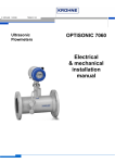
Operating Instructions Control Panels and Distribution Systems > 8125/5 Control Panel and Distribution System > 8125/8 Terminal Compartment Contents 1 Contents 1 2 3 4 5 6 7 8 9 10 11 2 Contents ................................................................................................................2 General Information ...............................................................................................2 General Safety Information ...................................................................................3 Designated Use .....................................................................................................4 Technical Data ......................................................................................................5 Transport, Storage and Disposal ...........................................................................6 Assembly ...............................................................................................................7 Installation .............................................................................................................8 Commissioning ....................................................................................................13 Maintenance ........................................................................................................14 Accessories and Spare Parts .............................................................................17 General Information 2.1 Manufacturer R. STAHL Schaltgeräte GmbH Am Bahnhof 30 74638 Waldenburg Germany Phone: Fax: Internet: +49 7942 943-0 +49 7942 943-4333 www.stahl-ex.com 2.2 Information regarding the Operating Instructions ID-No.: 134784 / 8125612300 Publication Code: 2013-01-18·BA00·III·en·05 We reserve the right to make technical changes without notice. 2.3 Symbols Used X Action request: Describes actions to be carried out by the user. Reaction sign: Describes the results or the reactions to the actions taken. Bullet Commentary sign: describes the notes and recommendations. Warning sign: Danger from energised parts! Warning sign: Danger due to an explosive atmosphere! 2 Control Panels and Distribution Systems 8125/5, 8125/8 134784 / 8125612300 2013-01-18·BA00·III·en·05 General Safety Information 3 General Safety Information 3.1 Safety Instructions for Assembly and Operating Personnel The operating instructions contain basic safety instructions which are to be observed during installation, operation and maintenance. Non-observance can lead to endangerment of persons, plant and the environment. WARNING Risk due to unauthorised work being performed on the device! Risk of injury and damage to equipment. Assembly, installation, commissioning, operation and maintenance must only be performed by personnel who are both authorised and suitably trained for this purpose. Before assembly/commissioning: Read through the operating instructions. Give adequate training to the assembly and operating personnel. Ensure that the contents of the operating instructions are fully understood by the personnel in charge. The national installation and assembly regulations (e.g. IEC/EN 60079-14) apply. If you have questions: Contact the manufacturer. When operating the device: Ensure the operating instructions are made available on location at all times. Observe safety instructions. Observe national safety and accident prevention regulations. Only run the device according to its performance data. Servicing/maintenance work or repairs which are not described in the operating instructions must not be performed without prior agreement with the manufacturer. Any damage may render explosion protection null and void. No changes to the device impairing their explosion protection are permitted. Install and use the device only if it is undamaged, dry and clean. 3.2 Warnings Warnings are sub-divided in these operating instructions according to the following scheme: WARNING Type and source of the danger! Possible consequences. Measures to avoid danger. They are always identified by the signalling word “WARNING“ and sometimes also have a symbol which is specific to the danger involved. 134784 / 8125612300 2013-01-18·BA00·III·en·05 Control Panels and Distribution Systems 8125/5, 8125/8 3 Designated Use 3.3 Conformity to Standards The conformity to the standards and regulations is specified in the corresponding certificates and declarations of the manufacturer (e.g. EC Declaration of Conformity). These documents are available for download on the internet page www.stahl-ex.com. 4 Designated Use The control and distribution boxes as well as the switch and distribution systems 8125/5, combined with their fitted components, are used to control, switch and transmit electrical energy. The terminal compartment enclosures 8125/8 are used as terminal compartments for enclosures of the type of protection “d” flameproof enclosure. All these devices are intended for stationary installation as standard. WARNING Only use the device for its intended purpose! Otherwise, the manufacturer’s liability and warranty expire. The device may only be used under the operating conditions described in these operating instructions. The device may only be used in hazardous areas according to these operating instructions. 4 Control Panels and Distribution Systems 8125/5, 8125/8 134784 / 8125612300 2013-01-18·BA00·III·en·05 Technical Data 5 Technical Data Explosion protection Global (IECEx) Gas and dust IECEx PTB 06.0079 Ex d e ia ib [ia Gb] mb q IIA, IIB, IIC T6, T5, T4 Gb Ex tb IIIC T 80 °C, T 95 °C, T 130 °C Db Europe (ATEX) Gas and dust PTB 01 ATEX 1001 E II 2 G Ex d e ia ib [ia Gb] q IIA, IIB, IIC T6, T5, T4 Gb E II 2 D Ex tb IIIC T 80 °C, T 95 °C, T 130 °C Db IP66 Material Enclosure Standard Galvanised sheet steel, painted in light grey (RAL 7032) Option Stainless steel 1.4404 (AISI 316L), electropolished, painting possible to order Seal Silicone foam Option: Polyurethane foam Cover lock Standard with captive M6 stainless steel combo head screws Option with cover hinges Rated voltage max. 1100 V AC / DC (depending on the type of terminal and Ex components used) Rated current max. 630 A (depending on the type of terminal and Ex components used) Rated cross-section max. 240 mm2 (depending on the type of terminal and Ex components used) Flanges Standard the enclosures are supplied without flanges in the standard version Option Depending on the order, the enclosures can be fitted on one or more sides with flanges; flange material: galvanised sheet steel or stainless steel Degree of protection IP66 (depending on the installed equipment) Operating temperature range - 60 ... + 100 °C ... (depending on the installed equipment) 134784 / 8125612300 2013-01-18·BA00·III·en·05 Control Panels and Distribution Systems 8125/5, 8125/8 5 Transport, Storage and Disposal Dimensional drawings (all dimensions in mm) - subject to alterations 04554E00 8125/.04. 04555E00 8125/.05. 04556E00 8125/.06. 04560E00 Additional dimension for flange 04557E00 8125/.07. 04558E00 8125/.08. Height of enclosure h 04559E00 Enclosure 8125/...1 91 mm 8125/...3 8125/...5 8125/...6 150 mm 190 mm 230 mm 8125/.04. X - - - 8125/.05. X - - - 8125/.06 X X - - 8125/.07. X X - - 8125/.08. X X X X 8125/.09. X X X - X ... can be supplied 8125/.09. 6 Transport, Storage and Disposal Transport Shock-free in its original carton, do not drop, handle carefully. Storage Store in a dry place in its original packaging Disposal Ensure environmentally friendly disposal of all components according to legal regulations. 6 Control Panels and Distribution Systems 8125/5, 8125/8 134784 / 8125612300 2013-01-18·BA00·III·en·05 Assembly 7 Assembly WARNING Danger due to not approved cable entries! If a not approved cable entry is used, explosion protection can no longer be guaranteed. Use only cable glands approved for the required type of protection. When selecting or using cable glands, the thread type and size indicated in the component documentation must be observed. WARNING Danger due to open holes or unused cable entries on the Ex "e" enclosure! The explosion protection can no longer be guaranteed if holes or unused cable entries of the Ex "e" enclosure are left open. Open holes must be sealed with separate stopping plugs suitable for this purpose in accordance with the certification of the control panel. WARNING Danger due to excessive weight! Use suitable lifting appliances. Secure against tipping. Install a protective roof or wall if the explosion-protected device is mounted outdoors. Information regarding mechanical assembly, such as location of attachment points, dimensions or weight of the combined switch panels, can be found in the enclosed assembly drawings. Use the included mounting kit for assembly or optionally the frame system 8298. (Assembly using the frame system only for enclosures 8125/.07., 8125/.08. and 8125/.09.) Observe the weight of the enclosure depending on the type and number of fitted components. To prevent condensation in the enclosure, we recommend using a type 8162 breather from R. STAHL Schaltgeräte GmbH. The installation of the breather reduces the type of protection as per IEC 60529. If installed vertically, breather at the bottom, the type of protection is IP 66, otherwise IP 64. 134784 / 8125612300 2013-01-18·BA00·III·en·05 Control Panels and Distribution Systems 8125/5, 8125/8 7 Installation 8 Installation WARNING Installation may only be performed by qualified personnel! Installation of the devices may only be carried out by appropriately authorised and trained personnel. Observe the relevant national regulations in the country of use. WARNING Danger due to non-observance of warning signs and instruction plates on the device! Read and observe all warning signs and instruction plates attached to the device before starting installation. WARNING Incorrectly installed components! Explosion protection cannot be guaranteed any more if the components are incorrectly installed. If terminal sleeves are used, they must be gas-tight and applied with a suitable tool. WARNING Use of cable entries without strain-relief! Explosion protection cannot be guaranteed any more if cable entries are installed without cable strain-relief in the vicinity of loosely laid cables and leads. Securely lay cables and leads. If the cables are laid loosely, only use cable entries approved for this application. 8 WARNING Danger due to not approved cable entries! If a not approved cable entry is used, explosion protection can no longer be guaranteed. When selecting or replacing cable glands, the thread type and size indicated in the component documentation must be observed. Use only cable glands approved for the required type of protection. To avoid an accumulation of moisture and dirt inside the combined switch panels, the electrical installation has to be executed under clean and dry ambient conditions. The enclosures must only be opened during installation works and be closed correctly after completing the work. Control Panels and Distribution Systems 8125/5, 8125/8 134784 / 8125612300 2013-01-18·BA00·III·en·05 Installation Opening and closing the enclosure cover Knob levers attached to the cover may have a cover lock. In this case, the cover can only be removed or closed in a definite position. Loosen the screws on the enclosure. Observe the cover lock on the knob lever, if any. Open and remove the enclosure cover carefully. For closing the cover, proceed in reverse order. Adhere to the specified tightening torque. Type 8125 Tightening torque [Nm] 4.5 Screw type Cheese-head screws M6 x 28 Back-up fuse Protect the system using the given electrical back-up fuse. Make sure that there is sufficient short-circuit current on the mains connection for tripping the fuse. 8.1 Internal wiring Cables WARNING For internal wiring, use only type of wires specified in the table. Temperature classes with different conductor types: Type H07G H05V2 or similar types Temperature class T5 T6 Conductor cross section ) 1 mm2, Cu WARNING Incorrectly routed cables in the Ex "e" enclosure! Explosion protection cannot be guaranteed any more if the wires are routed incorrectly. Strictly adhere to the required creepage distances and clearances. Mounting rails or elements must be fastened properly. Loosen the mounting rails or elements for connecting the cables correctly. After connecting the conductors, fasten the mounting rails or elements properly. 134784 / 8125612300 2013-01-18·BA00·III·en·05 Control Panels and Distribution Systems 8125/5, 8125/8 9 Installation Intrinsically safe circuits WARNING Danger due to incorrectly dimensioned cables and wires! Risk of severe injuries. Use only insulated cables and wires whose test voltage is minimum 500 V AC and whose minimum quality is H05. The diameter of one conductor must not be smaller than 0.1 mm. The diameter of individual wires of finely stranded conductors must not be smaller than 0.1 mm. WARNING Danger due to incorrectly routed cables and wires! Risk of short circuit. Wires and cables must be at a minimum distance of 8 mm to wires and cables of other intrinsically safe circuits. WARNING Danger due to incorrectly routed cables and wires! Risk of short circuit. An isolating plate at a distance of ( 1.5 mm to the enclosure wall must be provided between the connection points of intrinsically safe and nonintrinsically safe circuits. A distance of 50 mm around an insulating () 1 mm thick) or earthed metal ( ) 0.45 mm thick) isolating plate must be provided between the connection points of intrinsically safe and non-intrinsically safe circuits. Insulation test voltage With regard to the insulation and separation of terminals and cables, it should be noted that the insulation test voltage is derived from the sum of the rated operating voltages of intrinsically safe circuits. "Intrinsically safe against earth" In case of "intrinsically safe against earth" then the insulation voltage value is at least 500 V (or double the value of the rated operational voltage of intrinsically safe circuits). “Intrinsically safe against non intrinsically safe“ In case of "intrinsically safe against non-intrinsically safe", then the insulation voltage value is at least 1500 V (double the sum of the rated operational voltage of intrinsicallysafe circuits plus 1000 V). 10 The conductors of intrinsically safe or non-intrinsically safe circuits are protected by an earthed shield. Control Panels and Distribution Systems 8125/5, 8125/8 134784 / 8125612300 2013-01-18·BA00·III·en·05 Installation Terminal block in the Ex “e” enclosure Pay attention to the test certificate of the terminals. Only one conductor may be connected to each terminal. Terminal bridging is only permitted if original flameproof accessories have been used. Equip with the necessary partitions as needed. For additional protection against splaying use crimped terminal sleeves or cable lugs. The cross section of the anti-splay protection must meet the conductor cross section. 8.2 External wiring Guide the connecting cable together with the complete external insulation through the cable entry into the enclosure. Please ensure that the cable diameter and the terminal cross section on the cable entry are identical. Tighten the hexagon nut of the cable guide. Make sure that the tightness of the enclosure and the strain relief protection of the connection points is guaranteed. To determine the tightening torques, please consult the operating instructions of the individual components. Lay the connecting cables in the terminal compartment so that: The minimum permissible bending radii for the respective conductor cross section are achieved. Mechanical damage of the conductor isolation rubbing against sharp-edged or movable metal parts is avoided. WARNING Incorrect installation! Risk of severe injuries. Please observe the thread sizes for the cable entries specified in the equipment documentation. The connecting cable should comply with relevant regulations and have the required cross-section. The diameter must be identical to the data on the cable entry. Ensure that the maximum permissible conductor temperatures are not exceeded by suitable selection of cables and means of running them. The permissible ambient temperature around the intrinsically safe devices and components must not be exceeded. When stripping insulation, it must be ensured that the conductor insulation reaches right up to the terminals. The conductor itself must not be damaged when removing the insulation. 134784 / 8125612300 2013-01-18·BA00·III·en·05 Control Panels and Distribution Systems 8125/5, 8125/8 11 Installation Protective earth conductor Always connect the protective earth conductor. Regardless of the operating voltage, connect all bare, non-energised metal parts to the protective earth conductor. Consider the N conductor as being energised and lay it accordingly. Inactive metal parts are insulated in accordance with IEC/EN 60439-1 and not connected to PE. Please take the details relating to potential equalisation, earthing and intrinsically safe circuits from the documentation of the relevant equipment. Protective earth conductor for cable cross sections up to 70 mm2 Internal connection External connection 1 5 4 3 6 7 2 07855E00 Guide the earth bolt (1) through a suitable hole in the enclosure wall (2) and secure it by means of the hexagon nut (3). Slide the inner PE cable lug (4) onto the earth bolt (1). Secure the PE cable lug by means of lock washer and hexagon nut (5). Slide the outer PE cable lug (6) onto the earth bolt (1). Secure the PE cable lug by means of lock washer and hexagon nut (7). Protective earth conductor for cable cross section up to 35 mm (M6) and up to 70 mm2 (M8) External connection 1 2 3 Internal connection 4 07873E00 Clamp the outer PE conductor between the plates (2) and fasten it by means of hexagon nuts (1). Clamp the inner PE conductor between the plates (3) and fasten it by means of hexagon nuts (4). 12 Control Panels and Distribution Systems 8125/5, 8125/8 134784 / 8125612300 2013-01-18·BA00·III·en·05 Commissioning The following work is required after finishing electrical installation: Attach protection against contact. Set nominal values in all release devices. Check visually if there are loose metal parts, soiling or traces of moisture. If any, clean and dry the enclosure. Please make sure to consult the enclosed documentation such as wiring diagrams or similar. Connecting to the mains Open the enclosure. Lead the connecting cables with intact external insulation jackets through the cable entry. Lay the connecting cables so that the minimum permissible bending radii are achieved. The protective earth conductor must always be connected. Remove loose metal particles, dirt and traces of moisture from the terminal compartment, if any. Carefully close the enclosure after finishing the work. Test the insulation in accordance with IEC/EN 60439-1. 9 Commissioning Before commissioning Make sure that the device is not damaged. Make sure that the device is installed correctly. Remove any foreign object from the device. Check that cable entries and stopping plugs are tight. Check that screws and nuts are tightly fitted. Inspect cable entry for damage. Check tightening torques. Make sure that unused cable entries are sealed with plugs certified according to Directive 94/9/EC, and unused holes are sealed by stopping plugs certified according to Directive 94/9/EC. Check whether all covers and barriers for live parts are installed and fixed. We recommend the use of type 8290 stopping plugs for unused holes and type 8161 plugs for unused cable entries in the enclosure. Both are available from R. STAHL Schaltgeräte GmbH. 134784 / 8125612300 2013-01-18·BA00·III·en·05 Control Panels and Distribution Systems 8125/5, 8125/8 13 Maintenance 10 Maintenance WARNING Danger from energised parts! Risk of severe injuries. Before any maintenance work commences, disconnect the device from the power supply. Secure the device against unauthorised activation. Exception: Enclosures with intrinsically safe and non-intrinsically safe circuits with the notice "Non-intrinsically safe circuits protected by IP 30 cover" may be opened when supplied with power. WARNING Risk due to unauthorised work being performed on the device! Risk of injury and damage to equipment. Assembly, installation, commissioning, operation and maintenance must only be performed by personnel who are both authorised and suitably trained for this purpose. The dimensions of the flameproof joint do not comply with the tables in the standard IEC/EN 60079-1. Contact the manufacturer before starting to work on the joint faces. 10.1 Regular Maintenance Work Consult the relevant national regulations (e.g. IEC/EN 60079-17) to determine the type and extent of inspections. Plan the intervals so that any defects in the equipment which may be anticipated are promptly detected. To check as part of the maintenance schedule: X X X X Check that cables and lines are clamped properly. Inspect device for visible damage. Compliance with the permitted temperatures in accordance with IEC/EN 60079-0. Make sure that the device is used according to its designated use 10.2 Cleaning X Clean with a cloth, brush, vacuum cleaner or similar items. 14 Control Panels and Distribution Systems 8125/5, 8125/8 134784 / 8125612300 2013-01-18·BA00·III·en·05 Maintenance 10.3 Inspection / maintenance checklist Inspection schedule for Ex "d", "e" und "n" (D = Detailed inspection, C = Close inspection, V = Visual inspection) Please check the following: Type of protectio n "d" Type of protectio n "e" Type of protectio n "n" Grade of inspection D N S D N S D N S x x x x x x x x x x x x x x x A Equipment 1 Equipment is suitable for the respective zone x x 2 Equipment group is correct x x 3 Temperature class of equipment is correct x x 4 Circuit identification of equipment is correct x 5 Circuit identification of equipment is available x x x x x x x x x 6 Enclosure, windows and glass-to-metal sealing and/or compounds are satisfactory x x x x x x x x x 7 There are no unauthorised modifications x 8 There are no visible unauthorised modifications x x 9 Screws, cable glands (direct and indirect) and blind plugs are correct, complete and tight. x x x - Physical check x x x - Visual check 10 x x x x x x Joint faces are clean and undamaged, seals (if any) are satisfactory x x x x 11 Joint widths are within the allowed limit values x 12 Rated value, type and arrangement of the lamps are correct x 13 x x x Electrical connections are tight and fixed properly x x 14 Condition of the enclosure sealing is satisfactory x 15 Fracture-proof encapsulation and hermetically sealed devices are undamaged x 16 Restricted breathing enclosure is satisfactory x 17 Motor fans have sufficient clearance to enclosure and/or covers 18 Breathing and draining devices are satisfactory x x x x x x x x B Installation 1 Appropriate cable and conductor types are used x 2 There is no obvious damage to cables x x x x x x x x x 3 Sealing of trunking, ducts, pipes and/or conduits is satisfactory x x x x x x x x x 4 Sealing devices and terminal sleeves are correctly filled x 5 Integrity of conduit system and interface with mixed system is maintained x x x 6 Earth connections, including any supplementary equipotential bonding are satisfactory (for example, connections are properly fixed and the cross sections of the conductors are sufficient). x x x x x - Physical check - Visual check x x x x 7 Fault loop impedance (TN systems) or earthing resistance (IT systems) is satisfactory x x x 8 Insulation resistance is satisfactory x x x 9 Automatic electrical protective devices respond within the allowed limit values x x x 10 Automatic electrical protective devices are set correctly (auto-reset not possible) x x x 11 Special operating conditions (if applicable) are observed x x x 12 Cables not in use are correctly terminated x x x 13 Obstructions adjacent to flameproof joints are in accordance with IEC 60079-14 14 Variable voltage/frequency installation in accordance with documentation 134784 / 8125612300 2013-01-18·BA00·III·en·05 Control Panels and Distribution Systems 8125/5, 8125/8 15 Maintenance C Ambient conditions 1 Equipment is adequately protected against corrosion, weather, vibration and other adverse factors x x x x x x x x x 2 No undue accumulation of dust and dirt x x x x x x x x x 3 Electrical insulation is clean and dry x x NOTE 1 General information: Equipment having the types of protection “d” and “e” is checked using a combination of both columns. NOTE 2 Items B7 and B8: When using electrical test equipment, take into account that there could be an explosive atmosphere in the vicinity of the equipment. Inspection schedule for Ex "i" Please check the following: 16 Grade of inspection Detailed inspectio n Close inspectio n Visual inspectio n x A Equipment 1 Circuit and/or equipment documentation is appropriate to zone classification x x 2 Installed equipment corresponds to the equipment specified in the documentation - only applicable for stationary equipment x x 3 Category and group of the electric circuit and/or the equipment are correct x x 4 Temperature class of the equipment is correct x x 5 Installation is clearly labelled x x 6 There are no unauthorised modifications x 7 There are no visible unauthorised modifications 8 Safety barriers, relays and other energy limiting devices correspond to the approved type, are installed in accordance with the certifications and are securely earthed if necessary. x 9 Electrical connections are fixed properly x 10 Printed circuit boards are clean and undamaged x B Installation 1 Cables are installed in accordance with the documentation x 2 Cable screens are earthed in accordance with the documentation x 3 There is no obvious damage to cables 4 5 x x x x x x x Sealing of trunking, ducts, pipes and/or conduits is satisfactory x x x Point-to-point connections are all correct x 6 Earth continuity is satisfactory (for example, the connections are fixed properly and the conductor cross sections are sufficient) x 7 Earth connection maintain the integrity of the type of protection x x x 8 The intrinsically safe circuit is isolated from earth or grounded at one point only (refer to documentation) 9 Separation is maintained between intrinsically safe and non-intrinsically safe circuits in common distribution boxes or relay cubicles x 10 If applicable, short-circuit protection of the power supply is in accordance with the documentation x 11 Special operating conditions (if applicable) are observed x 12 Cables not in use are correctly terminated x x x C Ambient conditions 1 Equipment is adequately protected against corrosion, weather, vibration and other adverse factors x x x 2 No undue accumulation of dust and dirt x x x Control Panels and Distribution Systems 8125/5, 8125/8 134784 / 8125612300 2013-01-18·BA00·III·en·05 Accessories and Spare Parts 11 Accessories and Spare Parts WARNING Use of non-approved accessories and spare parts. The manufacturer’s liability and warranty expire. Use only original accessories and original spare parts manufactured by R. STAHL. Designation Illustration Description Order number Weight kg Flanges 05740E00 Size 1 sheet steel 134216 0.200 Size 1 stainless steel 135051 0.340 can be mounted on enclosue 05738E00 8125/.051 C/D 8125/.061 A/B/C/D 8125/.071 A/B/C/D 8125/.S71 C/D 8125/.081 A/B/C/D Size 2 sheet steel 134245 1.050 Size 2 stainless steel 135093 1.310 can be mounted on enclosue 05739E00 side 8125/.073 C/D 8125/.083; /.085 A/B/C/D 8125/.093; /.095 A/B/C/D Size 3 sheet steel 134274 1.050 Size 3 stainless steel 135125 0.630 can be mounted on enclosue Spacer side side 8125/.063 A/B/C/D 8125/.073 A/B Size 0 (68 mm x 68 mm) 136012 0.010 Size 1 (68 mm x 128 mm) 135974 0.020 Size 2 (126 mm x 266 mm) 136031 0.040 Size 3 (126 mm x 126 mm) 136235 0.100 04901E00 8125 for retrofitting to enclosure Kit consisting of: Cover hinges 05737E00 Mounting kit –– 2 hinges 134943 0.034 3 hinges 134949 0.051 2 mounting kits 134937 0.080 09019E00 134784 / 8125612300 2013-01-18·BA00·III·en·05 Control Panels and Distribution Systems 8125/5, 8125/8 17